Tiêu chuẩn iso 00005 4 2009
Bạn đang xem bản rút gọn của tài liệu. Xem và tải ngay bản đầy đủ của tài liệu tại đây (243.89 KB, 22 trang )
ISO
5-4
INTERNATIONAL
STANDARD
Third edition
2009-12-01
Part 4:
Geometric conditions for reflection
density
Photographie et technologie graphique — Mesurages de la densité —
Partie 4: Conditions géométriques pour la densité de réflexion
Reference number
ISO 5-4:2009(E)
Copyright International Organization for Standardization
Provided by IHS under license with ISO
No reproduction or networking permitted without license from IHS
© ISO 2009
Not for Resale
--`,,```,,,,````-`-`,,`,,`,`,,`---
Photography and graphic technology —
Density measurements —
ISO 5-4:2009(E)
PDF disclaimer
This PDF file may contain embedded typefaces. In accordance with Adobe's licensing policy, this file may be printed or viewed but
shall not be edited unless the typefaces which are embedded are licensed to and installed on the computer performing the editing. In
downloading this file, parties accept therein the responsibility of not infringing Adobe's licensing policy. The ISO Central Secretariat
accepts no liability in this area.
Adobe is a trademark of Adobe Systems Incorporated.
--`,,```,,,,````-`-`,,`,,`,`,,`---
Details of the software products used to create this PDF file can be found in the General Info relative to the file; the PDF-creation
parameters were optimized for printing. Every care has been taken to ensure that the file is suitable for use by ISO member bodies. In
the unlikely event that a problem relating to it is found, please inform the Central Secretariat at the address given below.
COPYRIGHT PROTECTED DOCUMENT
© ISO 2009
All rights reserved. Unless otherwise specified, no part of this publication may be reproduced or utilized in any form or by any means,
electronic or mechanical, including photocopying and microfilm, without permission in writing from either ISO at the address below or
ISO's member body in the country of the requester.
ISO copyright office
Case postale 56 • CH-1211 Geneva 20
Tel. + 41 22 749 01 11
Fax + 41 22 749 09 47
Web www.iso.org
Published in Switzerland
ii
Copyright International Organization for Standardization
Provided by IHS under license with ISO
No reproduction or networking permitted without license from IHS
© ISO 2009 – All rights reserved
Not for Resale
ISO 5-4:2009(E)
Contents
Page
Foreword ............................................................................................................................................................iv
Introduction.........................................................................................................................................................v
1
Scope ......................................................................................................................................................1
2
Normative references............................................................................................................................1
3
Terms and definitions ...........................................................................................................................2
4
Coordinate system, terminology and symbols ..................................................................................2
5
Distinction between ideal and realized parameters...........................................................................3
6
6.1
6.2
6.3
6.4
6.5
6.6
6.7
6.8
6.9
6.10
6.11
6.12
Requirements.........................................................................................................................................3
Influx and efflux geometry....................................................................................................................3
Sampling aperture .................................................................................................................................4
Annular distribution ..............................................................................................................................4
Normal directional distribution ............................................................................................................5
Determination of illuminator radiance distribution............................................................................5
Determination of receiver responsivity distribution..........................................................................5
Polarization efficiency...........................................................................................................................5
Scattered flux.........................................................................................................................................5
Backing material....................................................................................................................................6
Reference standard ...............................................................................................................................6
Designation ............................................................................................................................................7
Conformance testing.............................................................................................................................7
Annex A (normative) Determining conformance with tolerances..................................................................8
Annex B (normative) Determination of accuracy and linearity of a densitometer.......................................9
Annex C (normative) Certified reference materials for measuring instruments with polarizing
means ...................................................................................................................................................10
Annex D (normative) Polarization efficiency..................................................................................................11
Annex E (informative) Backing materials .......................................................................................................13
Annex F (informative) Reflectance density versus reflectance factor density...........................................14
--`,,```,,,,````-`-`,,`,,`,`,,`---
Bibliography......................................................................................................................................................15
iii
© ISO 2009 – All rights reserved
Copyright International Organization for Standardization
Provided by IHS under license with ISO
No reproduction or networking permitted without license from IHS
Not for Resale
ISO 5-4:2009(E)
Foreword
ISO (the International Organization for Standardization) is a worldwide federation of national standards bodies
(ISO member bodies). The work of preparing International Standards is normally carried out through ISO
technical committees. Each member body interested in a subject for which a technical committee has been
established has the right to be represented on that committee. International organizations, governmental and
non-governmental, in liaison with ISO, also take part in the work. ISO collaborates closely with the
International Electrotechnical Commission (IEC) on all matters of electrotechnical standardization.
International Standards are drafted in accordance with the rules given in the ISO/IEC Directives, Part 2.
The main task of technical committees is to prepare International Standards. Draft International Standards
adopted by the technical committees are circulated to the member bodies for voting. Publication as an
International Standard requires approval by at least 75 % of the member bodies casting a vote.
Attention is drawn to the possibility that some of the elements of this document may be the subject of patent
rights. ISO shall not be held responsible for identifying any or all such patent rights.
ISO 5-4 was prepared by ISO/TC 42, Photography, and ISO/TC 130, Graphic technology, in a Joint Working
Group.
This third edition cancels and replaces the second edition (ISO 5-4:1995), which has been technically revised.
This technical revision introduces the concept of ideal and practical conditions. In the course of this technical
revision, all parts of ISO 5 have been reviewed together, and the terminology, nomenclature and technical
requirements have been made consistent across all parts.
ISO 5 consists of the following parts, under the general title Photography and graphic technology — Density
measurements:
⎯
Part 1: Geometry and functional notation
⎯
Part 2: Geometric conditions for transmittance density
⎯
Part 3: Spectral conditions
⎯
Part 4: Geometric conditions for reflection density
--`,,```,,,,````-`-`,,`,,`,`,,`---
iv
Copyright International Organization for Standardization
Provided by IHS under license with ISO
No reproduction or networking permitted without license from IHS
© ISO 2009 – All rights reserved
Not for Resale
ISO 5-4:2009(E)
Introduction
This part of ISO 5 specifies the geometric conditions that are used to define ISO 5 standard reflection density
and to make measurements of ISO 5 standard reflection density. These conditions correspond approximately
to practical situations for viewing reflection-type photographs or graphic reproductions, which specifically
requires illuminating the print at an angle of 45° to the normal to the surface and viewing along the normal.
These conditions tend to reduce surface glare and maximize the density range of the image, which is
sometimes referred to as annular 45°:0° reflection densitometry.
The geometric conditions specified in this part of ISO 5 are intended to simulate 45° illumination for viewing or
photographing a specimen. There might be some engineering advantages in designing a measuring
instrument with normal illumination and 45° collection. Reversing the geometry in this way has no
demonstrated effect on the measured values in most cases, so both geometric arrangements are included in
this part of ISO 5. However, work by Voglesong[11] has demonstrated that there are times when
measurements of the same printed sample with 0°/45° & 45°/0° can be significantly different. This part of
ISO 5 attempts to specify unambiguously the geometric conditions that define reflection densitometry by
providing what is termed “ideal requirements”. The actual design and manufacture of instruments, however,
require tolerances around these ideal conditions which, in this part of ISO 5, are shown as practical
specifications.
This part of ISO 5 serves three primary functions:
a)
to provide the basis for unequivocal measurements that are needed for specifications, for communication
between organizations, and for contractual agreements;
b)
to provide a reference to assist in resolving seemingly different measurement data between systems; and
c)
to aid in the calibration and certification of densitometers, or spectrophotometers used as densitometers,
by allowing for the generation of certified reference materials (CRMs) with numerical values traceable to
fundamental physical phenomena.
For graphic arts applications, guidance in the use of densitometry is provided in ISO 13656.
--`,,```,,,,````-`-`,,`,,`,`,,`---
v
© ISO 2009 – All rights reserved
Copyright International Organization for Standardization
Provided by IHS under license with ISO
No reproduction or networking permitted without license from IHS
Not for Resale
--`,,```,,,,````-`-`,,`,,`,`,,`---
Copyright International Organization for Standardization
Provided by IHS under license with ISO
No reproduction or networking permitted without license from IHS
Not for Resale
INTERNATIONAL STANDARD
ISO 5-4:2009(E)
Part 4:
Geometric conditions for reflection density
1
--`,,```,,,,````-`-`,,`,,`,`,,`---
Photography and graphic technology — Density
measurements —
Scope
This part of ISO 5 specifies the geometric conditions for the definition of ISO 5 standard reflection density. It
also recommends tolerances on geometric conditions that can be used in the design of instruments. The
spectral conditions are specified in ISO 5-3.
This part of ISO 5 also specifies the requirements for polarization (if that feature is included) and for backing
material, and makes recommendations regarding accuracy and linearity.
Although intended primarily for use in the measurement of the reflection characteristics of photographic and
graphic arts materials, this part of ISO 5 is also applicable to the measurement of these characteristics for
other materials.
2
Normative references
The following referenced documents are indispensable for the application of this document. For dated
references, only the edition cited applies. For undated references, the latest edition of the referenced
document (including any amendments) applies.
ISO 5-1, Photography and graphic technology — Density measurements — Part 1: Geometry and functional
notation
ISO 5-3, Photography and graphic technology — Density measurements — Part 3: Spectral conditions
ISO 13655, Graphic technology — Spectral measurement and colorimetric computation for graphic arts
images
IEC 60050-845:19871), International Electrotechnical Vocabulary. Lighting
1) IEC 60050-845:1987 is a joint publication with the International Commission on Illumination (CIE). It is identical to
CIE 17.4:1987, International Lighting Vocabulary.
1
© ISO 2009 – All rights reserved
Copyright International Organization for Standardization
Provided by IHS under license with ISO
No reproduction or networking permitted without license from IHS
Not for Resale
ISO 5-4:2009(E)
3
Terms and definitions
For the purposes of this document, the terms and definitions given in ISO 5-1, IEC 60050-845:1987⏐CIE 17.4:1987
and the following apply.
3.1
certified reference material
CRM
reference material, accompanied by a certificate, one or more of whose property values are certified by a
procedure which establishes traceability to an accurate realization of the unit in which the property values are
expressed, and for which each certified value is accompanied by an uncertainty at a stated level of confidence
NOTE
Adapted from ISO Guide 30.
3.2
gloss suppression factor
P
numerical expression of the polarization efficiency of a densitometer with polarizing means
NOTE
For a precise definition of P, see Annex D.
3.3
receiver
portion of the densitometer that senses the efflux, including the collection optics and detector
3.4
reflection density
DR
negative logarithm to the base 10 of the reflectance factor
NOTE
The International Commission on Illumination (CIE) designates the measurement referred to as “reflection
density” in ISO 5 as “reflectance factor density”. (See IEC 60050-845:1987⏐CIE 17.4:1987.)
[ISO 5-1:2009, definition 3.19]
3.5
reflectance factor
R
ratio of the reflected flux to the absolute reference reflected flux under the same geometrical and spectral
conditions of measurement
[ISO 5-1:2009, definition 3.17]
3.6
screen ruling
number of image elements, such as dots or lines, per unit of length in the direction which produces the highest
value
NOTE
Adapted from ISO 12647-1.
3.7
screen width
reciprocal of screen ruling
NOTE
4
Adapted from ISO 12647-1.
Coordinate system, terminology and symbols
The coordinate system, terminology and symbols described in ISO 5-1 are used in this part of ISO 5 as a
basis for specifying the geometric conditions for reflection density measurements.
--`,,```,,,,````-`-`,,`,,`,`,,`---
2
Copyright International Organization for Standardization
Provided by IHS under license with ISO
No reproduction or networking permitted without license from IHS
© ISO 2009 – All rights reserved
Not for Resale
ISO 5-4:2009(E)
5
Distinction between ideal and realized parameters
The unambiguous definition of density requires that geometric, as well as spectral, parameters be exactly
specified. However, the practical design and manufacture of instruments require that reasonable tolerances
be allowed for physical parameters. The definition of ISO 5 standard reflection density shall be based on the
ideal value specified for each parameter. The tolerances shown for the realized parameter values represent
allowable variations of these standard parameters, which for many applications have an effect of less
than 0,01 on the density values resulting from measurements made with instruments. A method for
determining conformance of a realized parameter with the tolerances is given in Annex A.
Requirements
6.1
Influx and efflux geometry
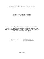
ISO 5 standard reflection measurements may be made with two equivalent measurement geometries. In the
“annular influx mode”, the geometry of the illuminator is annular and the geometry of the receiver is
directional. In the “annular efflux mode”, the geometry of the illuminator is directional and the geometry of the
receiver is annular. The annular influx mode is illustrated in Figure 1. The annular efflux mode would be
illustrated by Figure 1 if the arrows showing the radiant flux direction were reversed and the labels were
interchanged. The modes can be described in terms of specified annular and directional distributions of
illumination radiance (subscript i) or receiver responsivity (subscript r), depending on the mode. The cone halfangle κ (lower case Greek kappa, κ) is the angle between the angle of illumination or view (lower case Greek
theta, θ ) and the marginal ray.
The ideal angles of illumination and view and half-angles for the annular influx mode are θ i = 45°, θ r = 0°,
κ i = 5°, and κ r = 5°. The realized angles of illumination and view and half-angles for the annular influx mode
are θ i = 45° ± 2°, θ r = 0° ± 2°, κ i = 5° ± 1°, and κ r = 5° ± 1°.
For the annular efflux mode, the ideal angles of illumination and view and half-angles are θ i = 0°, θ r = 45°,
κ i = 5°, and κ r = 5°. The realized angles of illumination and view and half-angles for the annular efflux mode
are θ i = 0° ± 2°, θ r = 45° ± 2°, κ i = 5° ± 1°, and κ r = 5° ± 1°.
Key
1
influx
2
3
efflux
specimen
NOTE
Angles indicated represent the practical tolerances for the half-angle of the cone.
Figure 1 — Geometry of the annular influx mode
3
© ISO 2009 – All rights reserved
Copyright International Organization for Standardization
Provided by IHS under license with ISO
No reproduction or networking permitted without license from IHS
Not for Resale
--`,,```,,,,````-`-`,,`,,`,`,,`---
6
ISO 5-4:2009(E)
6.2
Sampling aperture
The extent and shape of the area on which density is measured are the sampling aperture. Physically, the
sampling aperture is realized by the optical systems of the illuminator and receiver. The size and shape of the
sampling aperture are not critical
a)
if no dimension is so large that the influx and efflux geometric conditions vary materially over the sampling
aperture, or
b)
if no dimension is so small that the effects of granularity, specimen texture, diffraction, or half-tone dot
structure become significant.
For case b), the diameter of a circular sampling aperture should not be less than 15 times the screen width; it
shall not be less than 10 times the screen width that corresponds to the lower limit for the screen ruling for
which the instrument is recommended by the manufacturer. The area of non-circular sampling apertures shall
not be smaller than that required for circular sampling apertures.
The sampling aperture is defined as the smaller of the illuminator region and the receiver region. Ideally, the
larger shall be greater than the smaller to the extent that any increase in size of the larger region has no effect
on the measurement result. The specimen characteristics over the illuminator region should be the same as
those over the receiver region.
NOTE 1
This requirement prevents lateral diffusion error.
The realized boundary of the larger of the illuminator region and the receiver region shall be outside the
boundary of the smaller by at least 2 mm. Where small sampling apertures are required, this dimension shall
be at least 0,5 mm. The magnitude of the resulting lateral diffusion error should be accepted as part of the
overall measurement uncertainty, or a greater boundary differential should be used.
NOTE 2
These dimensions are an acceptable compromise between the need to measure small areas and a negligible
uncertainty of measurement.
Any physical aperture present in the reference plane that is not used to limit either the illuminator region or
receiver region shall be kept well clear of both the influx and efflux beams.
The ideal illuminator radiance and receiver responsivity distributions shall be uniform over the sampling
aperture. The realized distributions shall be uniform to within 10 %. This can be determined by scanning the
sampling aperture laterally with a geometrically similar aperture, similarly oriented and having dimensions no
more than one-quarter of those of the corresponding dimensions of the sampling aperture. The radiance at
any place on the sampling aperture shall be at least 90 % of the maximum radiance.
NOTE 3
Lack of uniformity is immaterial when uniform specimens are measured, but can be an important source of
error in measurements of non-uniform specimens.
6.3
Annular distribution
The ideal angular distribution of radiance from the illuminator (influx) or of responsivity of the receiver (efflux)
shall be uniform for angles within the cone defined by the illuminator or receiver axis and half-angle and zero
for angles outside the cone. The realized angular distribution shall be uniform to within 10 % within the cone
and less than 2 % of the maximum of the cone distribution outside the cone.
The distribution of radiance from the illuminator or responsivity of the receiver shall be uniform around the
annulus, unless the reflection characteristics of the specimens to be measured do not change as they are
rotated in their own plane, in which case the realized radiance or responsivity need not be uniform around the
annulus.
4
Copyright International Organization for Standardization
Provided by IHS under license with ISO
No reproduction or networking permitted without license from IHS
--`,,```,,,,````-`-`,,`,,`,`,,`---
Not for Resale
© ISO 2009 – All rights reserved
ISO 5-4:2009(E)
For applications where specimens have been shown to have only a slight dependency on directional effects
(i.e. if density measurements made at azimuthal angles of 0°, 45°, and 90° differ by an amount that is less
than the tolerance acceptable for the intended application), strict uniform annular distribution may be replaced
by a distribution in which either:
⎯
the illuminator has a directional geometry at two azimuthal angles 90° apart (or, preferably, at more than
two equally spaced azimuthal angles), or
⎯
the receiver has a directional geometry at two azimuthal angles 90° apart (or, preferably, at more than
two equally spaced azimuthal angles).
6.4
Normal directional distribution
The ideal angular distribution of radiance from the illuminator (influx) or of responsivity of the receiver (efflux)
shall be uniform for angles within the cone defined by the half-angles and zero for angles outside the cone.
The realized angular distribution shall be uniform within 10 % within the cone and less than 2 % of the
maximum of the cone distribution outside the cone.
6.5
Determination of illuminator radiance distribution
The illuminator radiance distribution can be determined by placing a receiver having uniform angular response
over a conic distribution with a half-angle of 2° at the centre of the sampling aperture. Anormal angles are
scanned with the receiver both inside and outside the ideal influx cone, and the signal from the scanned
receiver is recorded at each angle. The signal at any angle within the influx cone shall be at least 90 % of the
maximum signal recorded. Outside the influx cone, the signal shall be less than 2 % of the maximum signal
recorded within the influx cone.
6.6
Determination of receiver responsivity distribution
The receiver responsivity distribution can be determined by placing a small beam with a conic distribution
having a half-angle of 2° at the centre of the sampling aperture. Anormal angles are scanned with the beam
both inside and outside the ideal efflux cone, and the signal from the receiver is recorded at each angle. The
signal for any angle within the efflux cone shall be at least 90 % of the maximum signal recorded. Outside the
efflux cone, the signal shall be less than 2 % of the maximum signal recorded within the efflux cone.
6.7
Polarization efficiency
Ideally, for ISO 5 standard density measurements made with polarization, gloss suppression shall be infinite
for every available spectral channel.
Practically, for measuring instruments with polarization means, the gloss suppression factor, as defined in
Annex D, shall be not less than 50 for every available spectral channel.
NOTE 1
Instruments with polarization means are common only in some graphic technology applications.
NOTE 2
Measurements made with polarization means will generally not match to those made without polarization.
6.8
Scattered flux
Scattered flux shall be reduced to a negligible amount by the use of clean optical components and appropriate
baffles, and by suitable blackening of surfaces exposed to the specimen, in accordance with good photometric
practice.
--`,,```,,,,````-`-`,,`,,`,`,,`---
5
© ISO for
2009
– All rights reserved
Copyright International Organization
Standardization
Provided by IHS under license with ISO
No reproduction or networking permitted without license from IHS
Not for Resale
ISO 5-4:2009(E)
6.9
Backing material
6.9.1
General
When measuring ISO 5 standard reflection density, the specimen shall be firmly positioned in the
measurement plane and backed by either a black or white backing that satisfies the characteristics specified
in 6.9.2 and 6.9.3. While density measurements may be made over either a black or white backing, a black
backing is the default condition and, unless otherwise indicated, shall be assumed to be the backing used.
Where white backing is used, the measurements shall be identified as being made “over white”.
Deviations from these criteria are allowed only if it can be demonstrated that another backing gives the same
results on the particular type of specimen being measured. In particular, the backing for opaque specimens is
not critical and need not meet these criteria.
See Annex E for additional discussion of backing materials.
6.9.2
Black backing
For measurements made over a black backing, the backing shall have all of the characteristics listed below.
a)
The backing shall have an infinite ISO 5 standard reflection density for all spectral products of interest.
For practical applications, the specimen shall be in contact with a backing material that has an ISO 5
visual reflection density of at least 1,30.
b)
The backing shall be spectrally non-selective, i.e. the total range of spectral reflection density throughout
the wavelength interval from 400 nm to 700 nm shall ideally be zero, while practically it shall not exceed
5 % of the average density obtained over the same interval.
c)
The backing shall be diffuse-reflecting, i.e. it shall have no perceptible specular reflection when viewed at
any angle under any illumination conditions.
d)
The backing shall be essentially opaque (one whose own reflection density does not depend on the
presence of or type of backing material used in its measurement).
As black backing is the default condition, unless otherwise noted, measurements shall be assumed to have
been made over black.
6.9.3
White backing
For measurements made over a white backing, the backing shall conform to the white backing specified in
ISO 13655. Such measurements shall be reported as being made “over white”.
NOTE 1
Density is a measure of the amount of light absorbed by the specimen. A white backing scatters light that was
not modulated by the specimen back into the receiver and thus lowers the density. ISO 13655 contains a recommendation
for white backing, but this measurement condition, while allowed for compatibility with ISO 13655, is not recommended for
the measurement of reflection density.
NOTE 2
The use of white backing is usually encountered in the graphic arts and colour management areas where
measurements of spectral data are used to compute both density and colorimetry.
6.10 Reference standard
ISO 5 standard reflection density is defined in relation to a perfectly reflecting and perfectly diffusing material.
Since such a perfect material does not exist, reference materials such as ceramic check plaques or barium
sulfate (BaSO4) are acceptable for use in maintaining calibration. The density relation between these and the
perfect material shall be known and utilized in determining ISO 5 standard reflection densities. Densitometer
manufacturers and national standardizing and metrology institutes can generally provide the ISO 5 standard
reflection density of such reference materials.
6
Copyright International Organization for Standardization
Provided by IHS under license with ISO
No reproduction or networking permitted without license from IHS
--`,,```,,,,````-`-`,,`,,`,`,,`---
© ISO 2009 – All rights reserved
Not for Resale
ISO 5-4:2009(E)
6.11 Designation
Density values obtained using the specifications given in 6.1 to 6.10 shall be referred to as “ISO 5 standard
reflection density”. In functional notation this shall be denoted as
⎯
DR(45 a°, 5°; S: 0°, 5°; s) for the annular influx mode, or
⎯
DR(0°, 5°; S: 45 a°, 5°; s) for the annular efflux mode,
where S is the spectral power distribution for reflection density, and s is the spectral responsivity of the
receiver. The allowed values for S and s shall be as given in ISO 5-3.
NOTE 1
The values for S identified in ISO 5-3 for reflection densitometry are A, M1, M2 and M3, where M3 also
denotes polarization.
NOTE 2
The values for s identified in ISO 5-3 for reflection densitometry are V, A, T, E, I and narrow-band.
The adjective describing the spectral product as defined in ISO 5-3 may be inserted before the word
“reflection”, and if a graphic arts influx is used, that may be added as a suffix.
EXAMPLE
“ISO 5 standard status E reflection density – M3”.
If a measurement is made over a white backing, it shall be identified as “over white”.
6.12 Conformance testing
Physical tolerances of specific instruments may vary depending on the application and materials being
measured, so that final determination of conformance will include an understanding of the application of the
measurements. It is the responsibility of the user, in conjunction with the instrument manufacturer, to
determine conformance of measured density to density as defined by this part of ISO 5. The use of
appropriate certified reference materials (CRMs) is recommended for testing of measurement systems.
--`,,```,,,,````-`-`,,`,,`,`,,`---
7
© ISO 2009 – All rights reserved
Copyright International Organization for Standardization
Provided by IHS under license with ISO
No reproduction or networking permitted without license from IHS
Not for Resale
ISO 5-4:2009(E)
Annex A
(normative)
Determining conformance with tolerances
A.1 General
A.2 Statement of conformance with specification
A densitometer conforms with this part of ISO 5 if the result of measurement y is between LLS + |U | and
LUS − |U | (denoted in ISO 14253-1 as the “conformance zone”), as shown in Equation (A.1):
LLS + |U | < y < LUS − |U |
(A.1)
where
LUS is the upper specification limit: a specified value giving the upper boundary of the permissible values
of a particular densitometer characteristic;
LLS
is the lower specification limit: a specified value giving the lower boundary of the permissible values
of a particular densitometer characteristic;
y
is the result of measurement: a value attributed to measurand Y (particular quantity subject to
measurement), obtained by a measurement;
U
is the expanded uncertainty: a quantity defining an interval about the result of a measurement that
may be expected to encompass a large fraction of the distribution of values that could reasonably
be attributed to the measurand (see ISO/IEC Guide 98-3).
The coverage factor, k, is a numerical factor used as a multiplier of the combined standard uncertainty in order
to obtain an expanded uncertainty. It is based on the level of confidence desired. For the purposes of this
annex, a coverage factor (k) of 2, equivalent to a confidence level of approximately 95 %, shall be used in the
determination of the expanded uncertainty.
EXAMPLE
The tolerance stated in this part of ISO 5 for the half-angle of maximum radiance in the annular influx
mode is 45° ± 2°, i.e. LLS = 43° and LUS = 47°. Suppose, as an example, that the expanded uncertainty associated with
the measurement of the half-angle of the influx cone is ±1° (k = 2). Hence, conformance with the specified tolerance is
demonstrated if the measured value of the half-angle of maximum radiance is between 44° and 46°.
NOTE
ISO/IEC Guide 98-3 provides additional material on this subject.
8
Copyright International Organization for Standardization
Provided by IHS under license with ISO
No reproduction or networking permitted without license from IHS
© ISO 2009 – All rights reserved
Not for Resale
--`,,```,,,,````-`-`,,`,,`,`,,`---
This part of ISO 5 gives tolerances for realized parameters. This annex defines a decision rule for determining
conformance with these specified tolerances, taking into account the estimated uncertainty associated with
the measurement of these parameters. This annex adopts the ideas and notations presented in ISO 14253-1,
which extensively discusses the matter of proving conformance with given specifications.
ISO 5-4:2009(E)
Annex B
(normative)
Determination of accuracy and linearity of a densitometer
After standardization of the densitometer on all channels in accordance with the manufacturer’s instructions,
the reflection densities of a CRM set conforming to ISO 15790 shall be measured with the instrument under
evaluation. On at least three CRMs covering a nominal ISO 5 standard reflection density range of (0,1 ± 0,1)
to (2,0 ± 0,5), the measured density shall agree with the density reported in the documentation accompanying
the CRM. The extent of this agreement (i.e. the accuracy) is best specified by the user, in accordance with the
requirements of the application. In the absence of such a specification, a generally acceptable accuracy is
± 0,02 % or ± 2 %, whichever is the greater.
For measuring instruments with polarizing means, the CRMs shall, in addition, conform to the requirements of
Annex C.
NOTE
The CRMs conforming to Annex C can also be used for measuring instruments without polarizing means.
--`,,```,,,,````-`-`,,`,,`,`,,`---
9
© ISO 2009 – All rights reserved
Copyright International Organization for Standardization
Provided by IHS under license with ISO
No reproduction or networking permitted without license from IHS
Not for Resale
ISO 5-4:2009(E)
Annex C
(normative)
Certified reference materials for measuring instruments
with polarizing means
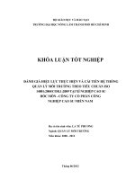
A CRM for linearity testing of measuring instruments with polarizing means shall consist of a white ceramic
plate with at least three “neutral density” absorptive glass filters attached to the surface (see Figure C.1). The
ceramic base plate shall have a plain matt white surface. The neutral absorptive glass filters shall be optically
polished, plain, and essentially spectrally non-selective (see 6.9). They shall be adhered to the ceramic plate
using a spectrally non-selective cement (see Figure C.1).
The filters should be selected such that the following ISO 5 visual reflection densities are realized by the
finished CRM set: 0,0 to 0,2; 1,0 ± 0,2; 2,0 ± 0,5.
In the documentation accompanying the CRM, the (absolute) ISO 5 standard reflection densities and their
uncertainties at a stated level of confidence shall be reported for the spectral conditions, including ISO 5 visual
reflection density and at least one of the following sets: ISO 5 status T, ISO 5 status I or ISO 5 status A.
Key
1, 2, 3 spectrally non-selective glass filters
4
ceramic base plate
Figure C.1 — Cross-section of the test object for measuring instruments with a polarizing means
NOTE 1
This construction of a CRM set provides an opportunity for calibration of measuring instruments with and
without polarization means, using the same set.
NOTE 2
10
For further information, see Reference [10].
Copyright International Organization for Standardization
Provided by IHS under license with ISO
No reproduction or networking permitted without license from IHS
--`,,```,,,,````-`-`,,`,,`,`,,`---
Not for Resale
© ISO 2009 – All rights reserved
ISO 5-4:2009(E)
Annex D
(normative)
Polarization efficiency
D.1 Determination of polarization efficiency
D.1.1 For simplicity, the method described in this annex applies to the case of a densitometer that is
intended to be used by placing it on top of a horizontal test object, but this does not preclude other types of
use.
D.1.2 Use a polarization test object (an example is described in D.2) and, for every spectral channel of the
measuring instrument, carry out the steps described in D.1.3 to D.1.9.
D.1.3 Remove the polarization means from the measuring instrument, and set it to zero on a white
reference.
D.1.4
Mount the polarization test object horizontally and place the measuring instrument on it.
D.1.5 Adjust the horizontal position of the measuring instrument, such that the reflection density reaches a
minimum.
D.1.6 Adjust the vertical position of the pointed cylinder, such that the reflection density again reaches a
minimum value, D1. If the detector and accompanying electronics operate outside their linear operating range,
or if an error condition is otherwise indicated, insert attenuating means into the light path and make sure they
do not disturb the geometry.
EXAMPLE
D.1.7
The insertion of a thin, spectrally non-selective density filter.
Reinstall the polarization means into the measuring instrument, and set it to zero, as in D.1.3.
--`,,```,,,,````-`-`,,`,,`,`,,`---
D.1.8 Place the measuring instrument back on the polarization test object at the same location at which the
minimum density was achieved in D.1.5.
D.1.9
Read the new reflection density, D2.
D.1.10 Calculate the gloss suppression factor, P, as shown in Equation (D.1):
P = 10 D 2 − D1
(D.1)
where
D1 is the density determined in D.1.5 (without polarization means);
D2 is the density determined in D.1.8 (with polarization means).
11
© ISO 2009 – All rights reserved
Copyright International Organization for Standardization
Provided by IHS under license with ISO
No reproduction or networking permitted without license from IHS
Not for Resale
ISO 5-4:2009(E)
D.2 Example polarization test object
The following description provides a means of realizing a practical polarization test object, but any other
design that can be shown to give essentially identical results is acceptable.
The test object should consist of a plate with a central, vertical and circular hole from which a snug-fitting
metallized cylinder should protrude partly (see Figure D.1). The diameter of the cylinder should be at least
4 mm greater than the widest dimension of the sampling aperture. The cylinder should have a conical point
with an angle of approximately 135°. The surface of the cone should be (22,5 ± 0,5)° from the surface defined
by the plate. The conical point should be spherically blunted at its very top, and the cone should be chromiumplated and highly polished. The vertical position of the pointed cylinder should be adjustable from below by
small increments.
NOTE
For further information, see Reference [10].
Dimensions in millimetres
Key
1
2
base plate
circular cylinder with conical point
Figure D.1 — Cross-section of polarization test object
--`,,```,,,,````-`-`,,`,,`,`,,`---
12
Copyright International Organization for Standardization
Provided by IHS under license with ISO
No reproduction or networking permitted without license from IHS
© ISO 2009 – All rights reserved
Not for Resale
ISO 5-4:2009(E)
Annex E
(informative)
Backing materials
For ISO 5 standard reflection density, previous editions of this part of ISO 5 specified that the backing material
should be spectrally non-selective and diffuse-reflecting (no perceptible specular reflection) and should have
an ISO 5 visual reflection density of at least 1,30. This choice was made to reduce measurement variability
introduced by both the backing material and the presence of printing or imaging on the reverse of a substrate.
--`,,```,,,,````-`-`,,`,,`,`,,`---
On thinner substrates and ones with lower transmission densities, the reflectance density of the backing has a
greater impact on the value of the reflection density measured. This impact is non-linear and is dependent on
both the opacity of the substrate and the density of the sample being measured. In all cases, the greatest
impact is on the measurement of the substrate alone (without either halftone or continuous tone image areas).
In the extreme, for a transparent substrate such as clear polyethylene film, the reflection density measurement
of the substrate alone is essentially a measurement of the backing material.
Although it is also much easier to specify and consistently maintain a high density (black) backing than it is a
low (white) density backing, there are many situations where measurements over a black backing are
meaningless; e.g. halftone images on clear polyethylene.
ISO 13655 has addressed this issue by also specifying a “standard white” backing which has also been
adopted for use in measurement of ISO 5 standard reflection density. Use of a “standard white” backing is
important where spectral reflectance measurements are used to compute both colorimetric data and density
data and the application of the colorimetric data requires white backing. A typical example of this requirement
is where proofs, which are typically made on a rather opaque substrate, are to be compared to printed images
made on a translucent substrate. In such a situation, both process control density data and image evaluation
colorimetric data need to have a common base that can only be provided if a white backing is used for the
measurements of the printed material on the translucent substrate.
The default measurement of ISO 5 standard reflection density is still based on use of black backing. However,
the introduction of a “standard white” backing is critical for many applications of reflection densitometry. Where
a white backing is used, it is important that its use be reported along with the data.
For those situations where traditional black backing can be used, its use should be maintained and
encouraged. Problems associated with maintaining the backing surface from the standpoint of spectral
neutrality, density and physical requirements are greatly reduced with a high-density black backing compared
to using a white backing. It should be noted that experience has shown that it is very difficult to find a durable
non-glossy surface with a density greater than 1,7. Therefore, if the density of the backing material reads
greater than 1,7, it is most likely that the diffuse character of the surface has been damaged and some
specular reflections are falling outside the pickup cone angle of the densitometer, in which case the material
should be replaced.
13
© ISO 2009 – All rights reserved
Copyright International Organization for Standardization
Provided by IHS under license with ISO
No reproduction or networking permitted without license from IHS
Not for Resale
ISO 5-4:2009(E)
Annex F
(informative)
Reflectance density versus reflectance factor density
The ISO 5 standard densities referred to in this part of ISO 5 are not reflectance densities, but reflectance
factor densities (often referred to as reflection densities). Thus, it is important to note the difference between
reflectance and reflectance factor, as described below.
a)
Reflectance, ρ , is defined as the ratio of the reflected flux, Φ r , to the incident flux, Φ i , in the given
conditions, as shown in Equation (F.1):
ρ=
Φr
Φi
(F.1)
Reflectance density, D ρ , is calculated as shown in Equation (F.2):
D ρ = − log 10 ρ = − log 10
b)
Φr
Φi
(F.2)
Reflectance factor, R , is the ratio of the flux reflected from the specimen, Φ r , to the flux reflected by a
perfectly reflecting and perfectly diffusing material, Φ rA , under identical geometric and spectral conditions
of illumination and sensing, as shown in Equation (F.3):
--`,,```,,,,````-`-`,,`,,`,`,,`---
R=
Φr
Φ rA
(F.3)
Reflection density (reflectance factor density), D R , is calculated as shown in Equation (F.4):
D R = − log 10 R = − log 10
Φr
Φ rA
(F.4)
It should be noted that, since some samples contain fluorescing materials, it is possible that under certain
spectral conditions such samples can have an apparent reflectance factor greater than 1,0.
14
Copyright International Organization for Standardization
Provided by IHS under license with ISO
No reproduction or networking permitted without license from IHS
© ISO 2009 – All rights reserved
Not for Resale