Tiêu chuẩn iso 01701 2 2004
Bạn đang xem bản rút gọn của tài liệu. Xem và tải ngay bản đầy đủ của tài liệu tại đây (319.37 KB, 28 trang )
INTERNATIONAL
STANDARD
ISO
1701-2
Second edition
2004-08-15
Test conditions for milling machines with
table of variable height — Testing of
accuracy —
Part 2:
Machines with vertical spindle
Conditions d'essai des machines à fraiser à table de hauteur variable —
Contrôle de la précision —
--`,,,,,,-`-`,,`,,`,`,,`---
Partie 2: Machines à broche verticale
Reference number
ISO 1701-2:2004(E)
Copyright International Organization for Standardization
Reproduced by IHS under license with ISO
No reproduction or networking permitted without license from IHS
© ISO 2004
Not for Resale
ISO 1701-2:2004(E)
PDF disclaimer
This PDF file may contain embedded typefaces. In accordance with Adobe's licensing policy, this file may be printed or viewed but
shall not be edited unless the typefaces which are embedded are licensed to and installed on the computer performing the editing. In
downloading this file, parties accept therein the responsibility of not infringing Adobe's licensing policy. The ISO Central Secretariat
accepts no liability in this area.
Adobe is a trademark of Adobe Systems Incorporated.
Details of the software products used to create this PDF file can be found in the General Info relative to the file; the PDF-creation
parameters were optimized for printing. Every care has been taken to ensure that the file is suitable for use by ISO member bodies. In
the unlikely event that a problem relating to it is found, please inform the Central Secretariat at the address given below.
© ISO 2004
All rights reserved. Unless otherwise specified, no part of this publication may be reproduced or utilized in any form or by any means,
electronic or mechanical, including photocopying and microfilm, without permission in writing from either ISO at the address below or
ISO's member body in the country of the requester.
ISO copyright office
Case postale 56 • CH-1211 Geneva 20
Tel. + 41 22 749 01 11
Fax + 41 22 749 09 47
Web www.iso.org
Published in Switzerland
--`,,,,,,-`-`,,`,,`,`,,`---
ii
Copyright International
Organization for Standardization
Reproduced by IHS under license with ISO
No reproduction or networking permitted without license from IHS
© ISO 2004 – All rights reserved
Not for Resale
ISO 1701-2:2004(E)
Contents
Page
Foreword ............................................................................................................................................................ iv
1
Scope...................................................................................................................................................... 1
2
Normative references ........................................................................................................................... 1
3
3.1
3.2
3.3
Terminology, designation of axes and milling operations ............................................................... 1
Terminology and designation of axes ................................................................................................ 1
Milling operations ................................................................................................................................. 4
Description of machines ...................................................................................................................... 4
4
4.1
4.2
4.3
4.4
4.5
4.6
4.7
Preliminary remarks.............................................................................................................................. 5
Measuring units..................................................................................................................................... 5
Reference to ISO 230-1 ......................................................................................................................... 5
Testing sequence.................................................................................................................................. 5
Tests to be performed .......................................................................................................................... 5
Measuring instruments......................................................................................................................... 5
Machining tests ..................................................................................................................................... 6
Minimum tolerance ............................................................................................................................... 6
5
5.1
5.2
5.3
Geometric tests ..................................................................................................................................... 7
Axes of motion ...................................................................................................................................... 7
Table ..................................................................................................................................................... 10
Spindle ................................................................................................................................................. 16
6
Machining tests ................................................................................................................................... 19
Annex A (informative) Equivalent terms in German, Italian, Dutch, Spanish and Swedish,
corresponding to Figure 1.................................................................................................................. 20
--`,,,,,,-`-`,,`,,`,`,,`---
Annex B (informative) Equivalent terms in German, Italian, Dutch, Spanish and Swedish,
corresponding to Figure 2.................................................................................................................. 21
Bibliography ..................................................................................................................................................... 22
iii
© ISO 2004 – All rights reserved
Copyright International Organization for Standardization
Reproduced by IHS under license with ISO
No reproduction or networking permitted without license from IHS
Not for Resale
ISO 1701-2:2004(E)
Foreword
ISO (the International Organization for Standardization) is a worldwide federation of national standards bodies
(ISO member bodies). The work of preparing International Standards is normally carried out through ISO
technical committees. Each member body interested in a subject for which a technical committee has been
established has the right to be represented on that committee. International organizations, governmental and
non-governmental, in liaison with ISO, also take part in the work. ISO collaborates closely with the
International Electrotechnical Commission (IEC) on all matters of electrotechnical standardization.
International Standards are drafted in accordance with the rules given in the ISO/IEC Directives, Part 2.
The main task of technical committees is to prepare International Standards. Draft International Standards
adopted by the technical committees are circulated to the member bodies for voting. Publication as an
International Standard requires approval by at least 75 % of the member bodies casting a vote.
Attention is drawn to the possibility that some of the elements of this document may be the subject of patent
rights. ISO shall not be held responsible for identifying any or all such patent rights.
ISO 1701-2 was prepared by Technical Committee ISO/TC 39, Machine tools, Subcommittee SC 2, Test
conditions for metal cutting machine tools.
This second edition of ISO 1701-2 as well as ISO 1701-1:2004 cancels and replaces ISO 1701-0:1984,
ISO 1701-2:1997 and ISO 1701-3:1997, which have been revised only editorially. The relevant sections of
ISO 1701-0 have been incorporated into this part of ISO 1701.
ISO 1701 consists of the following parts, under the general title Test conditions for milling machines with table
of variable height — Testing of accuracy:
Part 1: Machines with horizontal spindle
Part 2: Machines with vertical spindle
iv
--`,,,,,,-`-`,,`,,`,`,,`---
Copyright International Organization for Standardization
Reproduced by IHS under license with ISO
No reproduction or networking permitted without license from IHS
© ISO 2004 – All rights reserved
Not for Resale
INTERNATIONAL STANDARD
ISO 1701-2:2004(E)
Test conditions for milling machines with table of variable
height — Testing of accuracy —
Part 2:
Machines with vertical spindle
1
Scope
This part of ISO 1701 specifies, with reference to ISO 230-1, both geometric and machining tests on general
purpose, normal accuracy, vertical-spindle milling machines with table of variable height. It also specifies the
applicable tolerances corresponding to the above-mentioned tests.
NOTE
Milling machines with table of fixed height are covered by ISO 1984.
This part of ISO 1701 deals only with the verification of accuracy of the machine, and it does not apply to the
testing of the running of the machine (vibration, abnormal noise, stick-slip motion of components, etc.) or to
machine characteristics (such as speeds, feeds, etc.), which should generally be carried out before testing the
accuracy.
2
Normative references
The following referenced documents are indispensable for the application of this document. For dated
references, only the edition cited applies. For undated references, the latest edition of the referenced
document (including any amendments) applies.
ISO 230-1:1996, Test code for machine tools — Part 1: Geometric accuracy of machines operating under noload or finishing conditions
ISO 3855, Milling cutters — Nomenclature
3
3.1
Terminology, designation of axes and milling operations
Terminology and designation of axes
1
© ISO 2004 – All rights reserved
Copyright International Organization for Standardization
Reproduced by IHS under license with ISO
No reproduction or networking permitted without license from IHS
Not for Resale
--`,,,,,,-`-`,,`,,`,`,,`---
See Figures 1 and 2 and Tables 1 and 2.
ISO 1701-2:2004(E)
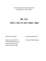
Figure 1 — Milling machine with table of variable height, with vertical spindle and
a sliding vertical saddle spindle head
Table 1 — Terminology
Designation
Key
English
French
Russian
1
Base-plate with tray
Socle
Основание
2
Column
Montant
Стойка
3
Knee
Console
Консоль
4
Knee slideways
Glissières de la console
Направляющие консоли
5
Saddle
Chariot transversal
Салазки
6
Saddle slideways
Glissières du mouvement
transversal de la table
Направляющие салазок
7
Table
Table porte-pièce
Стол
8
Table slideways
Glissières du mouvement
longitudinal de la table
Направляющие стола
9
Table surface
Surface utile de la table
Рабочая поверхность стола
10
Vertical feed-screw
Vis verticale
Винт вертикального
перемещения
11
Spindle nose
Nez de broche
Конец вертикального
шпинделя
12
Spindle head
Tête porte-broche
Шпиндельная бабка
13
Spindle head slideways
Glissière du mouvement
vertical de la tête porte-broche
Направляющие шпиндельной
бабки
NOTE
In addition to terms used in the three official ISO languages (English, French and Russian), this part of ISO 1701
gives in Annex A the equivalent terms in German, Spanish, Italian, Dutch and Swedish; these are published under the
responsibility of the member committees for Germany (DIN), Spain (AENOR), Italy (UNI), the Netherlands (NEN) and Sweden
(SIS). However, only the terms and definitions given in the official languages can be considered as ISO terms and definitions.
--`,,,,,,-`-`,,`,,`,`,,`---
2
Copyright International Organization for Standardization
Reproduced by IHS under license with ISO
No reproduction or networking permitted without license from IHS
© ISO 2004 – All rights reserved
Not for Resale
ISO 1701-2:2004(E)
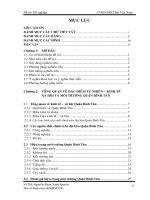
Figure 2 — Milling machine with table of variable height, with a movable head,
with horizontal or vertical spindle
Table 2 — Terminology
Designation
English
French
Russian
1
Base-plate with tray
Socle
Основание
2
Column
Montant
Стойка
3
Knee
Console
Консоль
4
Knee slideways
Glissières de la console
Направляющие консоли
5
Saddle
Chariot transversal
Салазки
6
Saddle slideways
Glissières du mouvement
transversal de la table
Направляющие салазок
7
Table
Table porte-pièce
Стол
8
Table slideways
Glissières du mouvement
longitudinal de la table
Направляющие стола
9
Table surface
Surface utile de la table
Рабочая поверхность стола
10
Vertical feed-screw
Vis verticale
Винт вертикального
перемещения
11
Vertical spindle nose
Nez de broche verticale
Конец вертикального
шпинделя
12
Horizontal spindle nose
Nez de broche horizontale
Конец горизонтального
шпинделя
13
Horizontal milling attachment
Dispositif de fraisage horizontal
Ползун
14
Movable head
Tête amovible
Поворотная головка
NOTE
In addition to terms used in the three official ISO languages (English, French and Russian), this part of ISO 1701
gives in Annex B the equivalent terms in German, Spanish, Italian, Dutch and Swedish; these are published under the
responsibility of the member committees for Germany (DIN), Spain (AENOR), Italy (UNI), the Netherlands (NEN) and Sweden
(SIS). However, only the terms and definitions given in the official languages can be considered as ISO terms and definitions.
3
© ISO 2004 – All rights reserved
Copyright International Organization for Standardization
Reproduced by IHS under license with ISO
No reproduction or networking permitted without license from IHS
--`,,,,,,-`-`,,`,,`,`,,`---
Key
Not for Resale
ISO 1701-2:2004(E)
3.2
Milling operations
Milling is a machining operation, which consists of removing material by means of a rotary tool called a “milling
cutter” of which there is several different types.
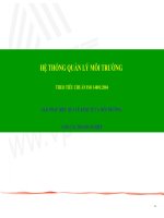
The usual operations of milling can be divided into three categories:
slab milling operations (see Figure 3);
face milling operations (see Figure 4);
end milling operations (see Figure 5).
Figure 3 — Slab milling operation
Figure 4 — Face milling operation
Figure 5 — End milling operation
3.3
Description of machines
In milling machines with table of variable height with vertical spindle, the base-plate is rigidly fixed to the
column (see Figures 1 and 2).
In this type of machine, the cutting movement is given by the spindle, the axis of which is vertical.
The feed movements are as follows:
The X axis of motion constitutes the longitudinal movement of the table.
The Y axis of motion constitutes the vertical movement of the table.
4
Copyright International Organization for Standardization
Reproduced by IHS under license with ISO
No reproduction or networking permitted without license from IHS
--`,,,,,,-`-`,,`,,`,`,,`---
a) Milling machine with vertical spindle (see Figure 1)
© ISO 2004 – All rights reserved
Not for Resale
ISO 1701-2:2004(E)
The Z axis of motion is parallel to the spindle axis and constitutes the vertical movement of the spindle
head.
The W axis of motion constitutes the vertical movement of the table.
b) Milling machine with movable head with horizontal or vertical spindle axis (see Figure 2)
The X axis of motion constitutes the longitudinal movement of the table.
The Y axis of motion constitutes the transverse movement of the table.
The Z axis of motion constitutes the vertical movement of the table.
NOTE
4
All these feed movements may be carried out by a rapid traverse of the element in question.
Preliminary remarks
4.1
Measuring units
In this part of ISO 1701, all linear dimensions, deviations and corresponding tolerances are expressed in
millimetres; angular dimensions are expressed in degrees, and angular deviations and the corresponding
tolerances are expressed in ratios but in some cases, microradians or arcseconds may be used for
clarification purposes. The equivalence of the following expressions should always be kept in mind:
0,010/1 000 = 10 x 10-6 = 10 àrad ê 2"
4.2
Reference to ISO 230-1
To apply this part of ISO 1701, reference shall be made to ISO 230-1, especially for the installation of the
machine before testing, warming up of the spindle and other moving components, description of measuring
methods and recommended accuracy of testing equipment.
In the “Observations” block of the tests described in Clauses 5 and 6, the instructions are followed by a
reference to the corresponding clause in ISO 230-1 in cases, where the test concerned is in compliance with
the specifications of that part of ISO 230.
4.3
Testing sequence
The sequence in which the tests are presented in this part of ISO 1701 in no way defines the practical order of
testing. In order to make the mounting of instruments or gauging easier, tests may be performed in any order.
4.4
Tests to be performed
When testing a machine, it is not always necessary or possible to carry out all the tests described in this part
of ISO 1701. When the tests are required for acceptance purposes, it is up to the user to choose, in
agreement with the supplier/manufacturer, those tests relating to the components and/or the properties of the
machine which are of interest. These tests are to be clearly stated when ordering a machine. Mere reference
to this part of ISO 1701 for the acceptance tests, without specifying the tests to be carried out, and without
agreement on the relevant expenses, cannot be considered as binding for any contracting party.
4.5
Measuring instruments
The measuring instruments indicated in the tests described in Clauses 5 and 6 are examples only. Other
instruments measuring the same quantities and having at least the same accuracy may be used. Dial gauges
shall have a resolution of 0,001 mm or better.
--`,,,,,,-`-`,,`,,`,`,,`---
5
© ISO 2004 – All rights reserved
Copyright International Organization for Standardization
Reproduced by IHS under license with ISO
No reproduction or networking permitted without license from IHS
Not for Resale
ISO 1701-2:2004(E)
4.6
Machining tests
4.7
--`,,,,,,-`-`,,`,,`,`,,`---
Machining tests shall be made with finishing cuts only, not with roughing cuts, which are liable to generate
appreciable cutting forces.
Minimum tolerance
When the tolerance for a geometric test is established for a measuring length different from that given in this
part of ISO 1701 (see 2.311 of ISO 230-1:1996), it shall be taken into consideration that the minimum value of
tolerance is 0,005 mm.
6
Copyright International Organization for Standardization
Reproduced by IHS under license with ISO
No reproduction or networking permitted without license from IHS
© ISO 2004 – All rights reserved
Not for Resale
ISO 1701-2:2004(E)
5
5.1
Geometric tests
Axes of motion
Object
G1
Checking of straightness of the vertical movement of the knee (W axis):
a)
in the vertical plane of symmetry of the machine (YZ plane);
b)
in the plane perpendicular to the vertical plane of symmetry of the machine (ZX plane).
Diagram
--`,,,,,,-`-`,,`,,`,`,,`---
Measured deviation
Tolerance
For a) and b)
0,020 for any measuring length of 300
a)
b)
Measuring instruments
Dial gauge and square.
Observations and references to ISO 230-1:1996
5.232.11
Instead of a straightedge, use the vertical arm of the square.
Adjust the square to obtain similar readings at both ends of its measuring length, then the maximum
difference of dial gauge readings gives straightness deviation.
Table in central position:
a)
saddle is) locked;
b)
table (X axis) locked.
If the spindle can be locked, the dial gauge may be mounted on it. If the spindle cannot be locked, the dial
gauge shall be placed on a fixed part of the machine.
7
© ISO 2004 – All rights reserved
Copyright International Organization for Standardization
Reproduced by IHS under license with ISO
No reproduction or networking permitted without license from IHS
Not for Resale
ISO 1701-2:2004(E)
Object
G2
Checking of squareness between the transverse saddle movement (Y axis) and the longitudinal table
movement (X axis).
Diagram
Tolerance
Measured deviation
0,02 for a measuring length of 300
Measuring instruments
Straightedge, dial gauge and square.
Observations and references to ISO 230-1:1996
5.522.4
Knee (W axis) locked.
a)
The straightedge shall be set parallel to the longitudinal table movement (X axis); then the square shall
be placed against the straightedge. The table shall then be locked in the central position. This test can
also be performed without the straightedge, aligning the long arm of the square parallel to the X axis.
b)
The transverse saddle movement (Y axis) shall then be checked.
If the spindle can be locked, then the dial gauge may be mounted on it. If the spindle cannot be locked, the
dial gauge shall be placed on a fixed part of the machine.
--`,,,,,,-`-`,,`,,`,`,,`---
8
Copyright International
Organization for Standardization
Reproduced by IHS under license with ISO
No reproduction or networking permitted without license from IHS
© ISO 2004 – All rights reserved
Not for Resale
ISO 1701-2:2004(E)
Object
G3
Checking of angular deviation of the table in its longitudinal movement (X axis):
a)
in the vertical YZ plane perpendicular to the table movement (roll EAX);
b)
in the vertical ZX plane parallel to the table movement (pitch EBX).
Diagram
a
Reference level.
Tolerance
Measured deviation
a)
0,04/1 000 (or 40 µrad or 8")
a)
b)
X u 1 000
0,08/1 000 (or 80 µrad or 16")
b)
X > 1 000
0,12/1 000 (or 120 µrad or 24")
Measuring instruments
Precision level
5.232.2
--`,,,,,,-`-`,,`,,`,`,,`---
Observations and references to ISO 230-1:1996
These tests should only be performed when the knee (W axis) is clamped on the column.
The level shall be placed in centre of the table
a)
transversely;
b)
longitudinally.
The reference level shall be located on the spindle head, and the spindle head shall be in the middle of the
travel range.
When X axis motion causes an angular movement of both the spindle head and work holding table,
differential measurements of the two angular movements shall be made and this shall be stated.
Measurements shall be taken at several positions, moving the table by 200 or 250 mm steps.
The difference between the maximum and minimum readings (excluding the above angular contribution) of
both directions of movement shall not exceed the tolerance.
9
© ISO 2004 – All rights reserved
Copyright International Organization for Standardization
Reproduced by IHS under license with ISO
No reproduction or networking permitted without license from IHS
Not for Resale
ISO 1701-2:2004(E)
5.2
Table
Object
G4
Checking of flatness of the table surface
Diagram
--`,,,,,,-`-`,,`,,`,`,,`---
Tolerance
Measured deviation
0,04 for a measuring length up to 1 000 (concave only)
For each 1 000 mm increase in table length, add 0,005
Maximum tolerance: 0,05
Local tolerance: 0,02 for any measuring length of 300
Measuring instruments
Precision level or straightedge and gauge blocks.
Observations and references to ISO 230-1:1996
5.322 and 5.323
Table (X axis) and saddle (Y axis) in the central position, table not locked, knee and cross slide locked.
NOTE
The alphabetical references on the diagram correspond to those used in Figure 41 of ISO 230-1:1996.
10
Copyright International Organization for Standardization
Reproduced by IHS under license with ISO
No reproduction or networking permitted without license from IHS
© ISO 2004 – All rights reserved
Not for Resale
ISO 1701-2:2004(E)
Object
G5
Checking of parallelism between the table surface and:
a)
the transverse saddle movement (Y axis), in the vertical YZ plane;
b)
its longitudinal movement (X axis), in the vertical ZX plane.
Diagram
Tolerance
Measured deviation
For a) and b)
0,025 for any measuring length of 300
a)
Maximum tolerance: 0,05
b)
Measuring instruments
Straightedge and dial gauge.
Observations and references to ISO 230-1:1996
5.422.21
The stylus of the dial gauge shall be placed approximately at the working position of the tool.
The measurement may be made on a straightedge laid parallel to the table surface.
If the table length is greater than 1 600 mm, carry out the inspection by succesive movements of the
straightedge.
Knee (W axis) locked:
a)
table (X axis) locked;
b)
saddle (Y axis) locked.
If the spindle can be locked, the dial gauge may be mounted on it. If the spindle cannot be locked, the dial
gauge shall be placed on a fixed part of the machine.
--`,,,,,,-`-`,,`,,`,`,,`---
11
© ISOfor2004
– All rights reserved
Copyright International Organization
Standardization
Reproduced by IHS under license with ISO
No reproduction or networking permitted without license from IHS
Not for Resale
ISO 1701-2:2004(E)
Object
G6
Checking of squareness between the table surface and the vertical movement of the knee
(W axis) (in three positions: in the middle and near the extremities of travel):
a)
in the vertical plane of symmetry of the machine (YZ plane);
b)
in the plane perpendicular to the vertical plane of symmetry of the machine (ZX plane).
Diagram
--`,,,,,,-`-`,,`,,`,`,,`---
Tolerance
Measured deviation
a)
0,025 for a measuring length of 300 with α u 90°
a)
b)
0,025 for a measuring length of 300
b)
Measuring instruments
Dial gauge and square.
Observations et références à l'ISO 230-1:1996
5.522.2
Table in central position, knee (W axis) locked when taking measurements;
a)
saddle (Y axis) locked;
b)
table (X axis) locked.
If the spindle can be locked, the dial gauge may be mounted on it. If the spindle cannot be locked, the dial
gauge shall be placed on a fixed part of the machine.
12
Copyright International Organization for Standardization
Reproduced by IHS under license with ISO
No reproduction or networking permitted without license from IHS
© ISO 2004 – All rights reserved
Not for Resale
ISO 1701-2:2004(E)
Object
G7
Checking of squareness between the table surface and the vertical movement of the spindle head slide (Z
axis):
a)
in the vertical plane of symmetry of the machine (YZ plane);
b)
in the plane perpendicular to the vertical plane of symmetry of the machine (ZX plane).
--`,,,,,,-`-`,,`,,`,`,,`---
Diagram
Tolerance
Measured deviation
a)
0,025 for a measuring length of 300 with α u 90°
a)
b)
0,025 for a measuring length of 300
b)
Measuring instruments
Dial gauge and square.
Observations and references to ISO 230-1:1996
5.522.2
Table in central position, knee (W axis) locked;
Spindle head slide (Z axis) locked when taking measurements;
a)
saddle (Y axis) locked;
b)
table (X axis) locked.
If the spindle can be locked, the dial gauge may be mounted on it. If the spindle cannot be locked, the dial
gauge shall be placed on the spindle head slide of the machine.
13
© ISO 2004 – All rights reserved
Copyright International Organization for Standardization
Reproduced by IHS under license with ISO
No reproduction or networking permitted without license from IHS
Not for Resale
ISO 1701-2:2004(E)
Object
G8
Checking of straightness of the median or reference T-slot of the table.
Diagram
Measured deviation
Tolerance
0,01 for a measuring length of 500
Maximum tolerance: 0,03
Measuring instruments
Straightedge and dial gauge or gauge blocks, or taut wire and microscope, or autocollimator.
Observations and references to ISO 230-1:1996
5.212, 5.212.1 and 5.212.23
The straightedge may be placed directly on the table.
14
Copyright International Organization for Standardization
Reproduced by IHS under license with ISO
No reproduction or networking permitted without license from IHS
--`,,,,,,-`-`,,`,,`,`,,`---
© ISO 2004 – All rights reserved
Not for Resale
ISO 1701-2:2004(E)
Object
G9
Checking of parallelism between the median or reference T-slot and the longitudinal movement of the table
(X axis).
Diagram
Tolerance
Measured deviation
0,015 for a measuring length of 300
Maximum tolerance: 0,04
--`,,,,,,-`-`,,`,,`,`,,`---
Measuring instruments
Dial gauge.
Observations and references to ISO 230-1:1996
5.422.1 and 5.422.21
Saddle (Y axis) and knee (W axis) locked.
If the spindle can be locked, the dial gauge may be mounted on it. If the spindle cannot be locked, the dial
gauge shall be placed on a fixed part of the machine.
15
© ISO 2004 – All rights reserved
Copyright International Organization for Standardization
Reproduced by IHS under license with ISO
No reproduction or networking permitted without license from IHS
Not for Resale
ISO 1701-2:2004(E)
5.3
Spindle
Object
G10
a)
Checking of run-out of the external centring surface on the spindle nose (for machines having this
feature).
b)
Checking of periodic axial slip.
c)
Checking of camming of the face of the spindle nose (including periodic axial slip).
Diagram
Tolerance
a) 0,01
Measured deviation
b) 0,01
c) 0,02
a)
b)
c)
Measuring instruments
Dial gauge.
Observations and references to ISO 230-1:1996
a)
5.612.2
b)
5.622.1 and 5.622.2
A force F, specified by the supplier/manufacturer of the machine, can be exerted by pressing towards
the housing during tests b) and c).
c) 5.632
The distance A of the dial gauge c) from the spindle axis shall be as large as possible.
16
--`,,,,,,-`-`,,`,,`,`,,`---
Copyright International Organization for Standardization
Reproduced by IHS under license with ISO
No reproduction or networking permitted without license from IHS
© ISO 2004 – All rights reserved
Not for Resale