Tiêu chuẩn iso 10618 2004
Bạn đang xem bản rút gọn của tài liệu. Xem và tải ngay bản đầy đủ của tài liệu tại đây (214.75 KB, 22 trang )
INTERNATIONAL
STANDARD
ISO
10618
Second edition
2004-08-15
Carbon fibre — Determination of tensile
properties of resin-impregnated yarn
Fibres de carbone — Détermination des propriétés en traction sur fils
imprégnés de résine
Reference number
ISO 10618:2004(E)
--``````-`-`,,`,,`,`,,`---
Copyright International Organization for Standardization
Reproduced by IHS under license with ISO
No reproduction or networking permitted without license from IHS
© ISO 2004
Not for Resale
ISO 10618:2004(E)
PDF disclaimer
This PDF file may contain embedded typefaces. In accordance with Adobe's licensing policy, this file may be printed or viewed but
shall not be edited unless the typefaces which are embedded are licensed to and installed on the computer performing the editing. In
downloading this file, parties accept therein the responsibility of not infringing Adobe's licensing policy. The ISO Central Secretariat
accepts no liability in this area.
Adobe is a trademark of Adobe Systems Incorporated.
Details of the software products used to create this PDF file can be found in the General Info relative to the file; the PDF-creation
parameters were optimized for printing. Every care has been taken to ensure that the file is suitable for use by ISO member bodies. In
the unlikely event that a problem relating to it is found, please inform the Central Secretariat at the address given below.
--``````-`-`,,`,,`,`,,`---
© ISO 2004
All rights reserved. Unless otherwise specified, no part of this publication may be reproduced or utilized in any form or by any means,
electronic or mechanical, including photocopying and microfilm, without permission in writing from either ISO at the address below or
ISO's member body in the country of the requester.
ISO copyright office
Case postale 56 • CH-1211 Geneva 20
Tel. + 41 22 749 01 11
Fax + 41 22 749 09 47
Web www.iso.org
Published in Switzerland
ii
Copyright International Organization for Standardization
Reproduced by IHS under license with ISO
No reproduction or networking permitted without license from IHS
© ISO 2004 – All rights reserved
Not for Resale
ISO 10618:2004(E)
Contents
Page
Foreword ............................................................................................................................................................ iv
1
Scope...................................................................................................................................................... 1
2
Normative references ........................................................................................................................... 1
3
Terms and definitions........................................................................................................................... 1
4
Symbols ................................................................................................................................................. 1
5
Principle ................................................................................................................................................. 2
6
Apparatus and materials ...................................................................................................................... 2
7
Test specimens ..................................................................................................................................... 3
8
Atmosphere for conditioning and testing .......................................................................................... 5
9
Procedure for tensile testing ............................................................................................................... 5
10
Expression of results............................................................................................................................ 6
11
Precision ................................................................................................................................................ 8
12
Test report.............................................................................................................................................. 8
--``````-`-`,,`,,`,`,,`---
Annex A (informative) Examples of heat-curable epoxy-resin systems ..................................................... 10
Annex B (informative) Examples of impregnating apparatus ...................................................................... 12
Annex C (informative) Examples of tabs and tab-preparation apparatus .................................................. 13
Annex D (informative) Examples of extensometers...................................................................................... 15
iii
© ISO 2004 – All rights reserved
Copyright International Organization for Standardization
Reproduced by IHS under license with ISO
No reproduction or networking permitted without license from IHS
Not for Resale
ISO 10618:2004(E)
Foreword
ISO (the International Organization for Standardization) is a worldwide federation of national standards bodies
(ISO member bodies). The work of preparing International Standards is normally carried out through ISO
technical committees. Each member body interested in a subject for which a technical committee has been
established has the right to be represented on that committee. International organizations, governmental and
non-governmental, in liaison with ISO, also take part in the work. ISO collaborates closely with the
International Electrotechnical Commission (IEC) on all matters of electrotechnical standardization.
International Standards are drafted in accordance with the rules given in the ISO/IEC Directives, Part 2.
The main task of technical committees is to prepare International Standards. Draft International Standards
adopted by the technical committees are circulated to the member bodies for voting. Publication as an
International Standard requires approval by at least 75 % of the member bodies casting a vote.
Attention is drawn to the possibility that some of the elements of this document may be the subject of patent
rights. ISO shall not be held responsible for identifying any or all such patent rights.
ISO 10618 was prepared by Technical Committee ISO/TC 61, Plastics, Subcommittee SC 13, Composites
and reinforcement fibres.
This second edition cancels and replaces the first edition (ISO 10618:1999), which has been technically
revised.
--``````-`-`,,`,,`,`,,`---
iv
Copyright International Organization for Standardization
Reproduced by IHS under license with ISO
No reproduction or networking permitted without license from IHS
© ISO 2004 – All rights reserved
Not for Resale
INTERNATIONAL STANDARD
ISO 10618:2004(E)
--``````-`-`,,`,,`,`,,`---
Carbon fibre — Determination of tensile properties of
resin-impregnated yarn
1
Scope
This International Standard specifies a method of test for the determination of the tensile strength, tensile
modulus of elasticity and strain at maximum load of a resin-impregnated yarn specimen. The method is
applicable to yarns (continuous and staple-fibre yarns) of carbon fibre for use as reinforcements in composite
materials.
2
Normative references
The following referenced documents are indispensable for the application of this document. For dated
references, only the edition cited applies. For undated references, the latest edition of the referenced
document (including any amendments) applies.
ISO 291, Plastics — Standard atmospheres for conditioning and testing
ISO 527-1, Plastics — Determination of tensile properties — Part 1: General principles
ISO 1889, Reinforcement yarns — Determination of linear density
ISO 10119, Carbon fibre — Determination of density
ISO 10548, Carbon fibre — Determination of size content
3
Terms and definitions
For the purposes of this document, the terms and definitions given in ISO 527-1 and the following apply.
3.1
cross-sectional area of carbon-fibre yarn
Af
the linear density of the yarn divided by the density of the carbon fibre
NOTE
4
It is expressed in square millimetres.
Symbols
The symbols used in this International Standard are as follows:
σf
tensile strength, in megapascals;
Ff
maximum tensile force, in newtons;
Af
cross-sectional area of yarn, in square millimetres;
1
© ISO 2004 – All rights reserved
Copyright International Organization for Standardization
Reproduced by IHS under license with ISO
No reproduction or networking permitted without license from IHS
Not for Resale
ISO 10618:2004(E)
ρf
density of yarn, in grams per cubic centimetre;
Ttf
linear density of yarn, in tex;
Tti
linear density of impregnated yarn, in tex;
Ef
tensile modulus of elasticity, in gigapascals;
L0
gauge length of extensometer, in millimetres;
∆L variation in the length, in millimetres, corresponding to the variation in the force, in newtons;
5
Principle
A sample of yarn is uniformly impregnated with resin, then cured to provide test specimens. The specimens
are loaded in tension at a constant speed by a suitable mechanical testing machine until failure.
The tensile strength, the tensile modulus of elasticity and the strain at maximum load are calculated from the
force-extension relationship.
The tensile modulus is determined by dividing the variation in the stress by the corresponding variation in the
strain between two defined points. For carbon-fibre yarns, the relation between stress and strain is not linear,
hence a chord modulus must be defined. In method A, the modulus is defined between two strain levels and in
method B it is defined between two load levels. The linear density and the size content have to be determined
independently.
NOTE
The precision of the values obtained is believed to be approximately the same for method A and for method B.
However, for the generally non-linear stress-strain response common to carbon fibres, the mean modulus values from
these two methods will be somewhat different and not necessarily statistically comparable. Method B, or other methods,
may be used in the purchase specification or for quality assurance by agreement between customer and supplier.
6
Apparatus and materials
6.1
Resin
The impregnating resin shall be compatible with the yarn and its size. The viscosity of the resin or resin
solution shall be such that sufficient resin pick-up is achieved to ensure uniform impregnation. The strain at
failure of the cured resin shall be at least twice that of the fibre, preferably three times. In this respect, heatcurable epoxy-resin systems with a viscosity during impregnation of preferably less than 1 000 mPa⋅s are
suitable (see Annex A for example) as is any formulation capable of giving test specimens that fulfill the
requirements of this International Standard. The resin formulation, however, shall be specified in detail and
shall be agreed upon between the fibre manufacturer and the user.
6.2
Impregnation apparatus
Test specimens can be prepared by any method which produces a uniformly impregnated, smooth specimen.
These methods include both single- and multiple-specimen preparation techniques. A multiple-specimen
impregnation apparatus may consist of:
6.2.1
A holder for the sample yarn bobbin, with yarn-tensioning devices.
6.2.2
bars.
An impregnation bath, with temperature-control devices and impregnation rollers or yarn-tensioning
2
Copyright International Organization for Standardization
Reproduced by IHS under license with ISO
No reproduction or networking permitted without license from IHS
© ISO 2004 – All rights reserved
Not for Resale
--``````-`-`,,`,,`,`,,`---
∆F variation in the force, in newtons, corresponding to the variation in the length, in millimetres.
ISO 10618:2004(E)
6.2.3 A unit to remove excess resin from the impregnated yarn by passing it over rollers covered with fabric,
paper or felt and/or through a die.
6.2.4
A frame to wind up the impregnated yarn, preferably made of wood or metal coated with rubber.
Examples of impregnation apparatus are given in Annex B.
6.3
Curing oven with temperature control
A fan circulation oven is preferable to ensure uniform curing of the resin.
6.4
Tensile-testing machine
6.4.1 Use a tensile-testing machine with a constant crosshead speed, equipped with force- and extensionrecording devices. The accuracy of the force indication shall be better than 1 % of the recorded value. The
specimen-gripping system shall ensure that the test specimen is aligned with the axis of the test machine.
6.4.2 The tensile-testing machine shall include an extensometer linked to a continuous-recording device
which automatically records the extension within the gauge length of the extensometer as a function of the
force on the test specimen. The extensometer should be sufficiently light to induce only negligible stresses in
the test specimen.
The gauge length of the extensometer shall be at least 50 mm but preferably 100 mm. The gauge length shall
be determined with a tolerance of ± 1 %.
--``````-`-`,,`,,`,`,,`---
The extensometer shall have a tolerance on deviation from linearity of not more than 0,1 % over the required
extension-measurement range.
Examples of suitable extensometers are given in Annex D. Other strain-measuring instruments, such as
optical or laser instruments, may be used, if suitable.
6.5
Balance
Use a balance readable to 0,1 g to weigh the test specimens to determine the linear density of the
impregnated yarn.
6.6
Ruler
Use a graduated ruler or other measuring device at least 500 mm long and accurate to ± 1 mm.
7
7.1
Test specimens
Number of test specimens
Prepare sufficient test specimens to enable four determinations to be made. If any of the specimens fails
within the grips or at the tabs, or because of damage caused by the extensometer, discard the result and carry
out a repeat determination on a fresh test specimen.
7.2
Length of test specimens
For test specimens with tabs, the length of the test specimen between the tabs shall be either (150 ± 5) mm or
(200 ± 5) mm. For test specimens without tabs, the total length of the test specimen shall be (250 ± 5) mm or
(300 ± 5) mm (at least the extensometer gauge length plus twice the grip length).
3
© ISO 2004 – All rights reserved
Copyright International Organization for Standardization
Reproduced by IHS under license with ISO
No reproduction or networking permitted without license from IHS
Not for Resale
ISO 10618:2004(E)
In cases of dispute, for test specimens with tabs, the length between the tabs shall be (150 ± 5) mm; for test
specimens without tabs, the length of the test specimen shall be (250 ± 5) mm.
7.3
Impregnation of test specimens
7.3.1
The procedure for using the impregnation apparatus described in 6.2 is as follows:
7.3.2
Place the yarn bobbin on the holder.
7.3.3 Pour the impregnating-resin mixture into the resin bath (6.2.2) and adjust the temperature and
viscosity to the desired values.
7.3.4 Draw the yarn through the resin bath and through the system designed to remove the excess resin
while ensuring adequate resin impregnation (see 6.2.3).
7.3.5 Adjust the unwinding tension. The unwinding tension used shall be at the discretion of the individual
test laboratory.
7.3.6
Wind the impregnated yarn onto the frame (6.2.4).
7.3.7
Place the frame in the oven (6.3).
7.3.8
Cure the resin in accordance with the resin manufacturer's instructions.
7.3.9 When the resin has been cured, remove the frame from the oven. After removal of the impregnated
yarn from the frame, cut off a sufficient number of test specimens.
7.3.10 Select the test specimens according to the criteria given in 7.5.
7.4
7.4.1
Determination of other fibre properties
General
In order to make the calculations of tensile strength and tensile modulus given in Clause 10, the properties
specified in 7.4.2 to 7.4.5 must be determined.
7.4.2
Linear density of the yarn
Determine the linear density of the yarn by the method given in ISO 1889.
7.4.3
Size content of the yarn
Determine the size content of the yarn by the method given in ISO 10548.
7.4.4
Density of the carbon fibre
Determine the density of the carbon fibre by one of the methods given in ISO 10119.
7.4.5
Linear density of impregnated-yarn test specimen
Measure the length of a test specimen (see 6.6), after it has been cut to length and prior to tabbing. Weigh the
specimen (see 6.5).
Calculate the linear density of the impregnated yarn by dividing the mass of the test specimen by its length,
expressing the result in grams per kilometre (tex).
NOTE
It is not necessary to determine the linear density of the impregnated yarn for each specimen.
--``````-`-`,,`,,`,`,,`---
4
Copyright International Organization for Standardization
Reproduced by IHS under license with ISO
No reproduction or networking permitted without license from IHS
© ISO 2004 – All rights reserved
Not for Resale
ISO 10618:2004(E)
7.5
Criteria for selection of test specimens
7.5.1 Each test specimen shall be confirmed as straight when checked using a suitable jig. It shall be
uniform in appearance and without any of the following defects:
broken filaments;
resin droplets;
fibre misalignment.
7.5.2 The resin content shall be at least 30 % by mass. The resin content of the specimens can be
calculated from the linear density of the test specimen and the linear density of the yarn from the equation:
Resin content (%) =
T ti − T tf
× 100
T ti
(1)
Tti
is the linear density of the test specimen, in tex;
Ttf
is the linear density of the yarn, in tex.
--``````-`-`,,`,,`,`,,`---
where
For each preparation batch, a control sample of each yarn type being tested shall be verified for correct resin
content. If the resin content of the control sample is outside the acceptable range, each set of specimens from
that batch shall be verified for correct resin content.
7.5.3
7.6
The yarn shall be uniformly impregnated.
Preparation of test specimens with tabs
If a test specimen fails within the grips of the tensile-testing machine, the result is not valid. Affixing tabs to the
test specimen may help to reduce the frequency of such failures. They may also help to assure correct
alignment of the test specimen in the grips.
Specimens can be tested with or without tabs.
If tabs are necessary, the equipment required depends on the type of tab chosen. In all cases where tabs are
used, the gripped length shall be at least 30 mm. See Annex C.
8
Atmosphere for conditioning and testing
The atmosphere used for conditioning and testing shall be selected from those defined in ISO 291.
9
Procedure for tensile testing
9.1 Set the cross-head speed of the tensile-testing machine (see 6.4.1). The maximum recommended
speed is 250 mm/min. The maximum practical speed may be limited by the speed of the data-sampling or
recording equipment.
5
© ISO 2004 – All rights reserved
Copyright International Organization for Standardization
Reproduced by IHS under license with ISO
No reproduction or networking permitted without license from IHS
Not for Resale
ISO 10618:2004(E)
9.2 For test specimens with tabs, install grips which fit the type of tab used. Adjust the distance between the
grips to the prescribed specimen length (see 7.2).
For test specimens without tabs, install grips which are equipped with flat faces made of sheet materials of
moderate elasticity and high coefficient of friction, such as hard rubber sheet. The sheet can be bonded onto
the metal face of the grips with a suitable adhesive. If test specimens are found to slip within the grips during
the test, it has been found useful to insert abrasive paper between the test specimen and the faces of the
grips.
Because the test specimens are so fragile, it is recommended that the grip system is actuated by compressed
air.
9.3
Clamp a test specimen in the grips of the test machine.
9.4
Fix the extensometer (see 6.4.2) carefully on the test specimen.
9.5
Start the recording device and load the test specimen to failure.
9.6 If the test specimen fails within the grips or the tabs, or because of damage caused by the
extensometer, discard the result and carry out a repeat test on a fresh test specimen.
10 Expression of results
10.1.1 For each test specimen, calculate the tensile strength of the yarn from the following equation:
σf =
Ff
Af
(2)
where
σf
is the tensile strength, in megapascals;
Ff
is the maximum tensile force, in newtons;
Af
is the cross-sectional area of the yarn, in square millimetres, given by the equation:
T
A f = tf × 10 −3
(3)
ρf
Ttf
being the linear density, in tex, of the yarn without size, calculated from the linear density
determined in accordance with ISO 1889 and the size content determined in accordance
with ISO 10548;
ρf
being the density of the yarn, in grams per cubic centimetre, determined in accordance with
ISO 10119.
If the size content is sufficiently low for no error to be introduced, the linear density and density of the yarn
with size may be used.
10.1.2 Calculate the arithmetic mean of the individual tensile-strength determinations and report as the result.
If required in the product specification or by the person requesting the test, calculate the standard deviation
and coefficient of variation of the individual determinations using normal statistical calculation methods.
6
Copyright International Organization for Standardization
Reproduced by IHS under license with ISO
No reproduction or networking permitted without license from IHS
© ISO 2004 – All rights reserved
Not for Resale
--``````-`-`,,`,,`,`,,`---
10.1 Tensile strength
ISO 10618:2004(E)
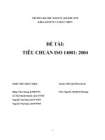
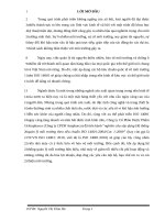
10.2 Tensile modulus of elasticity (see Figure 1)
10.2.1 Method A
The tensile modulus of elasticity as determined by Method A is calculated from the following equation:
Ef =
∆F L 0
×
× 10 −3
A f ∆L
(4)
where
Ef
is the tensile modulus of elasticity, in gigapascals;
∆F is the variation in the force, in newtons, corresponding to the variation in the length, in millimetres,
between the strain limits defined in Table 1;
Af
is the cross-sectional area of the yarn, in square millimetres [see Equation (3)];
∆L is the variation in the length, in millimetres, corresponding to the variation in the force, resulting from
the strain levels to be selected from Table 1.
Table 1 — Relationship between fibre type and strain limits
Strain at break ε typical of fibre type
Strain limits
ε W 1,2 %
0,1 % to 0,6 %
0,6 % u ε < 1,2 %
0,1 % to 0,3 %
0,3 % u ε < 0,6 %
0,05 % to 0,15 %
NOTE
The typical value of the strain at break (percent elongation at maximum load) may
be determined by extensometry or calculated from typical strength and tensile-modulus values
for the type of carbon fibre under test.
10.2.2 Method B
The tensile modulus of elasticity as determined by method B is calculated from the following equation:
Ef =
∆F L 0
×
× 10 −3
A f ∆L
(5)
where
Ef
is the tensile modulus of elasticity, in gigapascals;
∆F is the variation in the force, in newtons, corresponding to the variation in the length, in millimetres,
between 400 mN/tex and 800 mN/tex;
Af
is the cross-sectional area of the yarn, in square millimetres [see Equation (3)];
L0 is the gauge length of the extensometer, in millimetres;
∆L is the variation in the length, in millimetres, corresponding to the variation in the force between
400 mN/tex and 800 mN/tex.
7
© ISO 2004 – All rights reserved
Copyright International Organization for Standardization
Reproduced by IHS under license with ISO
No reproduction or networking permitted without license from IHS
Not for Resale
--``````-`-`,,`,,`,`,,`---
L0 is the gauge length of the extensometer, in millimetres;
ISO 10618:2004(E)
10.2.3 Calculate the arithmetic mean of the individual tensile-modulus determinations and report as the result.
State in the test report whether method A, method B or another method was used.
If required in the product specification or by the person requesting the test, calculate the standard deviation
and coefficient of variation of the individual determinations using normal statistical calculation methods.
10.3 Strain at maximum load (percent elongation at failure)
10.3.2 The strain at maximum load εE as determined by extensometry is calculated from the following
equation:
εE =
Lu − L0
× 100
L0
(6)
where
Lu
is the gauge length of the extensometer at maximum load, in millimetres;
L0
is the gauge length of the extensometer at zero load, in millimetres.
10.3.3 The strain at maximum load εC as determined by calculation from the tensile strength and tensile
modulus is calculated from the following equation:
εC =
σf
Ef
× 0,1
(7)
where
σf
is the tensile strength, in megapascals;
Ef
is the tensile modulus of elasticity, in gigapascals (see 10.2).
10.3.4 Calculate the arithmetic mean of the individual strain determinations and report as the result. If
required in the product specification or by the person requesting the test, calculate the standard deviation and
coefficient of variation of the individual determinations using normal statistical calculation methods.
11 Precision
The precision of this test method is not known because inter-laboratory data are not available. Inter-laboratory
data are being obtained and a precision statement will be added at the next revision.
12 Test report
The test report shall include the following:
a)
a reference to this International Standard;
b)
all details necessary for complete identification of the yarn tested;
c)
the linear density of the yarn;
d)
the density of the yarn;
8
Copyright International Organization for Standardization
Reproduced by IHS under license with ISO
No reproduction or networking permitted without license from IHS
© ISO 2004 – All rights reserved
Not for Resale
--``````-`-`,,`,,`,`,,`---
10.3.1 The strain at maximum load can be determined by extensometry or by calculation from the tensile
strength and tensile modulus. It is a dimensionless quantity, expressed as a percentage.
ISO 10618:2004(E)
whether the extension to maximum load was calculated or determined experimentally;
f)
the number of test specimens tested, including the number discarded;
g)
the results obtained for the tensile strength, tensile modulus of elasticity and strain (percent elongation) at
maximum load, and, if required, the individual results for each test specimen;
h)
the method of calculation of the tensile modulus of elasticity;
i)
any additional details which may have had a bearing on the results obtained.
--``````-`-`,,`,,`,`,,`---
e)
Key
X
extension (mm)
Y
force (N)
Figure 1 — Force-extension relationship during tensile testing
9
© ISO 2004 – All rights reserved
Copyright International Organization for Standardization
Reproduced by IHS under license with ISO
No reproduction or networking permitted without license from IHS
Not for Resale
ISO 10618:2004(E)
Annex A
(informative)
Examples of heat-curable epoxy-resin systems
Resin system
1)
2)
3,4-Epoxycyclohexyl 3,4-epoxycyclohexanecarboxylate
(see Note 1)
or
4g
130 °C for 30 min
Diglycidyl ether bisphenol A (DGEBA) (see Note 2) with
a viscosity of 11 000 mP⋅s to 14 000 mP⋅s at 25 °C and
an epoxy equivalent of 184 g/equiv to 194 g/equiv
100 g
Room temperature for 10 h
followed by 90 °C for 2 h
and then 150 °C for 4 h
Methyl nadic anhydrique (MNA) (see Note 3)
90 g
or
1 g to 2 g
5g
Room temperature for 10 h
followed by 100 °C for 2 h
and then 150 °C for 2 h
Epoxy resin: same as in Example 2
100 g
80 °C for 2 h followed by 200 °C for 1 h
Methyltetrahydrophthalic anhydride
90 g
or
3 g to 4 g
80 °C for 2 h followed by 150 °C for 4 h
Epoxy resin: same as in Example 2
100 g
70 °C for 3 h
Dimethyldiaminocyclohexylmethane
30 g
or
Arbitrary
80 °C for 2 h
Epoxy resin: same as in Example 2
100 g
Bis(4-aminophenyl)sulfone
20 g
80 °C for 1 h followed by
200 °C for 2 h
Boron trifluoride monoethylamine (BF3MEA)
1,5 g
Solvent
Solvent
6)
125 °C for 1 h
2-Propanone or ethanol
Benzyldimethylamine
5)
100 g
3g
2-Propanone
4)
Cure conditions
Boron trifluoride monoethylamine (BF3MEA)
Benzyldimethylamine
3)
Amount
Arbitrary
Epoxy resin: same as in Example 2
100 g
Boron trifluoride monoethylamine (BF3MEA)
3g
2-Butanone
20 g
200 °C for 40 min
--``````-`-`,,`,,`,`,,`---
10
Copyright International Organization for Standardization
Reproduced by IHS under license with ISO
No reproduction or networking permitted without license from IHS
© ISO 2004 – All rights reserved
Not for Resale
ISO 10618:2004(E)
NOTE 1
The structure is as follows:
NOTE 2
The structure is as follows:
NOTE 3
Methyl-5-norbornene-2,3-dicarboxylic anhydride.
--``````-`-`,,`,,`,`,,`---
11
© ISO 2004 – All rights reserved
Copyright International Organization for Standardization
Reproduced by IHS under license with ISO
No reproduction or networking permitted without license from IHS
Not for Resale
ISO 10618:2004(E)
Annex B
(informative)
--``````-`-`,,`,,`,`,,`---
Examples of impregnating apparatus
12
Copyright International Organization for Standardization
Reproduced by IHS under license with ISO
No reproduction or networking permitted without license from IHS
© ISO 2004 – All rights reserved
Not for Resale
ISO 10618:2004(E)
Annex C
(informative)
Examples of tabs and tab-preparation apparatus
cardboard;
metal plates;
resin-impregnated textile-glass fabrics;
cast thermoset resins;
thermoplastics.
Other materials may also be used.
When tab preparation is required, it is important that the method chosen gives acceptable, in particular
straight, test specimens.
Dimensions in millimetres
a
Variant 1: (150 ± 5) mm; variant 2: (200 ± 5) mm.
b
Variant 1: (250 ± 5) mm; variant 2: (300 ± 5) mm.
NOTE
A mould to prepare the tabs is required.
Figure C.1 — Thermoplastic-resin tabs
Dimensions in millimetres
a
Variant 1: (150 ± 5) mm; variant 2: (200 ± 5) mm.
b
Variant 1: (300 ± 5) mm; variant 2: (350 ± 5) mm.
NOTE
A mould to prepare the tabs is required.
Figure C.2 — Thermoset-resin tabs
13
© ISO 2004 – All rights reserved
Copyright International Organization for Standardization
Reproduced by IHS under license with ISO
No reproduction or networking permitted without license from IHS
Not for Resale
--``````-`-`,,`,,`,`,,`---
Various tabs and tabbing techniques are possible. Examples of possible materials are:
ISO 10618:2004(E)
Dimensions in millimetres
a
Variant 1: (150 ± 5) mm; variant 2: (200 ± 5) mm.
b
Variant 1: (250 ± 5) mm; variant 2: (300 ± 5) mm.
NOTE
No special apparatus is required.
Figure C.3 — Cardboard tabs
--``````-`-`,,`,,`,`,,`---
Dimensions in millimetres
a
Variant 1: (150 ± 5) mm; variant 2: (200 ± 5) mm.
NOTE
No special apparatus is required.
Figure C.4 — Metal-plate tabs
14
Copyright International Organization for Standardization
Reproduced by IHS under license with ISO
No reproduction or networking permitted without license from IHS
© ISO 2004 – All rights reserved
Not for Resale
ISO 10618:2004(E)
Annex D
(informative)
Examples of extensometers
The test specimen is a thin resin-impregnated CFRP rod with a diameter in the range from about 0,3 mm (for
1 000-filament yarn) to about 1 mm (for 12 000-filament yarn).
Extensometers which are usually used on round or rectangular test specimens are hard to fix to resinimpregnated yarn specimens for the following reasons:
a)
the extensometer is too heavy to fix to such a small-diameter specimen;
b)
the knife edge of the extensometer and a spring or rubber band are difficult to fix tightly to such a smalldiameter specimen.
The following types of extensometer are recommended:
a)
an automatic servo-controlled extensometer built into the tensile-testing machine;
b)
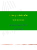
an extensometer which is mounted on the frame of the tensile-testing machine by means of a mounting
bracket as shown in Figure D.1;
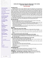
c)
an extensometer as shown in Figure D.2, which is built into a horizontal tensile-testing machine (one
fixture is stationary while the other is moveable and is connected to one end of an optical displacementmeasurement device which pivots on the frame).
© ISO 2004 – All rights reserved
Copyright International Organization for Standardization
Reproduced by IHS under license with ISO
No reproduction or networking permitted without license from IHS
--``````-`-`,,`,,`,`,,`---
Not for Resale
15
--``````-`-`,,`,,`,`,,`---
ISO 10618:2004(E)
Key
1
frame of tensile-testing machine
2
3
extensometer
mounting bracket
4
5
spring or rubber band
test specimen
Figure D.1 — Extensometer mounted on frame of tensile-testing machine
16
Copyright International Organization for Standardization
Reproduced by IHS under license with ISO
No reproduction or networking permitted without license from IHS
© ISO 2004 – All rights reserved
Not for Resale