Tiêu chuẩn tiêu chuẩn iso 10052 2004
Bạn đang xem bản rút gọn của tài liệu. Xem và tải ngay bản đầy đủ của tài liệu tại đây (532.18 KB, 38 trang )
INTERNATIONAL
STANDARD
ISO
10052
First edition
2004-12-15
Acoustics — Field measurements of
airborne and impact sound insulation and
of service equipment sound — Survey
method
Acoustique — Mesurages in situ de l'isolement aux bruits aériens et de
la transmission des bruits de choc ainsi que du bruit des
équipements — Méthode de contrôle
Reference number
ISO 10052:2004(E)
--`,,,`,,-`-`,,`,,`,`,,`---
Copyright International Organization for Standardization
Reproduced by IHS under license with ISO
No reproduction or networking permitted without license from IHS
© ISO 2004
Not for Resale
ISO 10052:2004(E)
--`,,,`,,-`-`,,`,,`,`,,`---
PDF disclaimer
This PDF file may contain embedded typefaces. In accordance with Adobe's licensing policy, this file may be printed or viewed but
shall not be edited unless the typefaces which are embedded are licensed to and installed on the computer performing the editing. In
downloading this file, parties accept therein the responsibility of not infringing Adobe's licensing policy. The ISO Central Secretariat
accepts no liability in this area.
Adobe is a trademark of Adobe Systems Incorporated.
Details of the software products used to create this PDF file can be found in the General Info relative to the file; the PDF-creation
parameters were optimized for printing. Every care has been taken to ensure that the file is suitable for use by ISO member bodies. In
the unlikely event that a problem relating to it is found, please inform the Central Secretariat at the address given below.
© ISO 2004
All rights reserved. Unless otherwise specified, no part of this publication may be reproduced or utilized in any form or by any means,
electronic or mechanical, including photocopying and microfilm, without permission in writing from either ISO at the address below or
ISO's member body in the country of the requester.
ISO copyright office
Case postale 56 • CH-1211 Geneva 20
Tel. + 41 22 749 01 11
Fax + 41 22 749 09 47
Web www.iso.org
Published in Switzerland
ii
Copyright International Organization for Standardization
Reproduced by IHS under license with ISO
No reproduction or networking permitted without license from IHS
© ISO 2004 – All rights reserved
Not for Resale
ISO 10052:2004(E)
Foreword
ISO (the International Organization for Standardization) is a worldwide federation of national standards bodies
(ISO member bodies). The work of preparing International Standards is normally carried out through ISO
technical committees. Each member body interested in a subject for which a technical committee has been
established has the right to be represented on that committee. International organizations, governmental and
non-governmental, in liaison with ISO, also take part in the work. ISO collaborates closely with the
International Electrotechnical Commission (IEC) on all matters of electrotechnical standardization.
International Standards are drafted in accordance with the rules given in the ISO/IEC Directives, Part 2.
The main task of technical committees is to prepare International Standards. Draft International Standards
adopted by the technical committees are circulated to the member bodies for voting. Publication as an
International Standard requires approval by at least 75 % of the member bodies casting a vote.
Attention is drawn to the possibility that some of the elements of this document may be the subject of patent
rights. ISO shall not be held responsible for identifying any or all such patent rights.
ISO 10052 was prepared by the European Committee for Standardization (CEN) in collaboration with
Technical Committee ISO/TC 43, Acoustics, Subcommittee SC 2, Building acoustics, in accordance with the
Agreement on technical cooperation between ISO and CEN (Vienna Agreement).
Throughout the text of this document, read “...this European Standard...” to mean “...this International
Standard...”.
© ISO 2004 – All rights reserved
Copyright International Organization for Standardization
Reproduced by IHS under license with ISO
No reproduction or networking permitted without license from IHS
--`,,,`,,-`-`,,`,,`,`,,`---
Not for Resale
iii
ISO 10052:2004(E)
Contents
Page
Foreword..............................................................................................................................................................v
1
Scope ......................................................................................................................................................1
2
Normative references ............................................................................................................................1
3
Terms and definitions ...........................................................................................................................1
4
Single number quantities......................................................................................................................7
5
Instrumentation......................................................................................................................................7
6
6.1
6.2
6.2.1
6.2.2
6.2.3
6.2.4
6.3
6.3.1
6.3.2
6.3.3
6.4
6.5
6.6
Test procedure and evaluation.............................................................................................................8
General....................................................................................................................................................8
Generation of sound field .....................................................................................................................8
General....................................................................................................................................................8
Airborne sound insulation between rooms ........................................................................................8
Impact sound insulation between rooms............................................................................................9
Airborne sound insulation of faỗades .................................................................................................9
Measurement of sound pressure levels ............................................................................................10
Airborne and impact sound insulation between rooms ..................................................................10
Airborne sound insulation of faỗades ...............................................................................................10
Service equipment sound pressure level..........................................................................................11
Frequency range of measurements ...................................................................................................11
Reverberation index data....................................................................................................................11
Precision...............................................................................................................................................14
7
7.1
7.2
7.3
Expression of results ..........................................................................................................................14
Airborne sound insulation ..................................................................................................................14
Impact sound insulation .....................................................................................................................14
Service equipment sound pressure level..........................................................................................14
8
Test report ............................................................................................................................................15
Annex B (normative) Operating conditions and operating cycles for measuring the maximum
sound pressure level and the equivalent continuous sound pressure level ................................23
B.1
General principles................................................................................................................................23
B.1.1 General..................................................................................................................................................23
B.1.2 Maximum sound pressure level (Lmax)..............................................................................................23
B.1.3 Equivalent continuous sound pressure level (Leq) ..........................................................................23
B.2
Water installations ...............................................................................................................................23
B.2.1 General operating conditions.............................................................................................................23
B.2.2 Water tap...............................................................................................................................................24
B.2.3 Shower cabin........................................................................................................................................25
B.2.4 Bath (tub) ..............................................................................................................................................25
B.2.5 Filling and emptying sinks and baths................................................................................................25
B.2.6 Water closet (Toilet).............................................................................................................................26
B.3
Mechanical ventilation ........................................................................................................................26
B.4
Heating and cooling service equipment............................................................................................27
B.5
Lift (Elevator)........................................................................................................................................27
B.6
Rubbish chute ......................................................................................................................................28
B.7
Boilers, blowers, pumps and other auxiliary service equipment ..................................................28
B.8
Motor driven car park door .................................................................................................................28
B.9
Other types of building service equipment.......................................................................................29
Bibliography ......................................................................................................................................................30
iv
Copyright International Organization for Standardization
Reproduced by IHS under license with ISO
No reproduction or networking permitted without license from IHS
© ISO 2004 – All rights reserved
Not for Resale
--`,,,`,,-`-`,,`,,`,`,,`---
Annex A (informative) Forms for the expression of results........................................................................17
ISO 10052:2004(E)
Foreword
This document (EN ISO 10052:2004) has been prepared by Technical Committee CEN/TC 126 “Acoustic
properties of building products and of buildings”, the secretariat of which is held by AFNOR, in collaboration
with Technical Committee ISO/TC 43 “Acoustics”.
This European Standard shall be given the status of a national standard, either by publication of an identical
text or by endorsement, at the latest by June 2005, and conflicting national standards shall be withdrawn at
the latest by June 2005.
--`,,,`,,-`-`,,`,,`,`,,`---
According to the CEN/CENELEC Internal Regulations, the national standards organizations of the following
countries are bound to implement this European Standard: Austria, Belgium, Cyprus, Czech Republic,
Denmark, Estonia, Finland, France, Germany, Greece, Hungary, Iceland, Ireland, Italy, Latvia, Lithuania,
Luxembourg, Malta, Netherlands, Norway, Poland, Portugal, Slovakia, Slovenia, Spain, Sweden, Switzerland
and United Kingdom.
v
© ISO 2004 – All rights reserved
Copyright International Organization for Standardization
Reproduced by IHS under license with ISO
No reproduction or networking permitted without license from IHS
Not for Resale
ISO 10052:2004(E)
Introduction
This document describes survey test methods which can be used for surveying the acoustic characteristics of
the airborne sound insulation, impact sound insulation and of the sound pressure levels from service
equipment. The methods may be used for screening tests of the acoustical properties of buildings. The
methods are not intended to be applied for measuring acoustical properties of building elements.
The approach of the survey methods is to simplify the measurement of sound pressure levels in rooms by
using a hand-held sound level instrument and by manually sweeping the microphone in the room space. The
correction for reverberation time can be either estimated by usage of tabular values or be based on
measurements. The measurement of airborne and impact sound insulation is carried out in octave bands. For
measuring sound from domestic service equipment, A - or C -weighted sound pressure levels are recorded.
Measurements are performed with specified operation conditions and operation cycles. The operating
conditions and operating cycles given in Annex B are only used if they are not opposed to national
requirements and regulations.
The measurement uncertainty of the results obtained using the survey method is a priori larger than the
uncertainty inherent in the corresponding test methods on engineering level.
--`,,,`,,-`-`,,`,,`,`,,`---
NOTE
Engineering methods for field measurements of airborne and impact sound insulation are dealt with in
EN ISO 140-4 and EN ISO 140-7. Engineering methods for field measurements of airborne sound insulation of faỗade
elements and faỗades are dealt with in EN ISO 140-5. An engineering method for measurement of service equipment
sound is dealt with in EN ISO 16032.
vi
Copyright International Organization for Standardization
Reproduced by IHS under license with ISO
No reproduction or networking permitted without license from IHS
© ISO 2004 – All rights reserved
Not for Resale
ISO 10052:2004(E)
1
Scope
This document specifies field survey methods for measuring:
a) airborne sound insulation between rooms;
b) impact sound insulation of floors;
c) airborne sound insulation of faỗades; and
d) sound pressure levels in rooms caused by service equipment.
The methods described in this document are applicable for measurements in rooms of dwellings or in rooms
of comparable size with a maximum of 150 m3.
For airborne sound insulation, impact sound insulation and faỗade sound insulation the method gives values
which are (octave band) frequency dependent. They can be converted into a single number characterising the
acoustical performances by application of EN ISO 717-1 and EN ISO 717-2. For service equipment sound the
results are given directly in A - or C -weighted sound pressure levels.
2
Normative references
The following referenced documents are indispensable for the application of this document. For dated
references, only the edition cited applies. For undated references, the latest edition of the referenced
document (including any amendments) applies.
EN 20140-2, Acoustics — Measurement of sound insulation in buildings and of building elements — Part 2:
Determination, verification and application of precision data (ISO 140-2:1991).
EN 61260, Electroacoustics - Octave-band and fractional-octave-band filters (IEC 61260:1995).
EN 60651, Sound level meters (IEC 60651:1993).
EN 60804, Integrating-averaging sound level meters (IEC 60804:2000).
EN ISO 140-7:1998, Measurements of sound insulation in buildings and of building elements — Part 7: Field
measurements of impact sound insulation of floors (ISO 140-7:1998).
--`,,,`,,-`-`,,`,,`,`,,`---
EN ISO 717-1, Acoustics — Rating of sound insulation in buildings and of building elements — Part 1:
Airborne sound insulation (ISO 717-1:1996).
EN ISO 717-2, Acoustics — Rating of sound insulation in buildings and of building elements — Part 2: Impact
sound insulation (ISO 717-2:1996).
EN ISO 3822-1, Acoustics - Laboratory tests on noise emission from appliances and equipment used in water
supply installations - Part 1: Method of measurement (ISO 3822-1:1999)
3
Terms and definitions
For the purposes of this document, the following terms and definitions apply.
1
© ISO 2004 – All rights reserved
Copyright International Organization for Standardization
Reproduced by IHS under license with ISO
No reproduction or networking permitted without license from IHS
Not for Resale
ISO 10052:2004(E)
3.1
average sound pressure level in a room L
ten times the logarithm to the base 10 of the ratio of the space and time average of the sound pressure
squared to the square of the reference sound pressure, the space average being taken over the entire room
with the exception of those parts where the direct radiation of a sound source or the near field of the
boundaries (wall, etc.) is of significant influence. It is expressed in decibels as:
L = 10lg
1
Tm
Tm
∫0 p
t dt
dB
2
2
(1)
p0
where
p
is the sound pressure level, in Pascal, p0 = 20 µPa is the reference sound pressure;
3.2
level difference D
difference in the space and time average sound pressure levels produced in two rooms by one sound source
in one of them. It is expressed in decibels as:
D = L1 − L2
dB
(2)
where
L1 is the average sound pressure level in the source room, in decibels;
L2 is the average sound pressure level in the receiving room, in decibels
3.3
reverberation index k
ten times the logarithm to the base 10 of the ratio of the actual reverberation time T of the receiving room to
the reference reverberation time T0. It is expressed in decibels. This quantity is denoted by:
k = 10 lg T dB
T0
(3)
where
T0 = 0,5 s
3.4
standardized level difference DnT
level difference corresponding to a reference value of the reverberation time in the receiving room. It is
expressed in decibels as:
DnT = D + k
dB
(4)
where
D
is the level difference (see equation (2)), in decibels;
k
is the reverberation index (see equation (3)), in decibels
2
Copyright International Organization for Standardization
Reproduced by IHS under license with ISO
No reproduction or networking permitted without license from IHS
© ISO 2004 – All rights reserved
Not for Resale
--`,,,`,,-`-`,,`,,`,`,,`---
Tm is the integration time in seconds
ISO 10052:2004(E)
3.5
normalized level difference Dn
level difference D corresponding to the reference absorption area in the receiving room. It is expressed in
decibels as:
Dn = D + k + 10 lg
A0 T0
dB
0 ,16 V
(5)
where
k
is the reverberation index;
T0
is the reference reverberation time (T0 = 0,5 s);
V
is the volume of the receiving room, in cubic metres;
A0
is the reference equivalent absorption area, in square metres, (A0 = 10 m2);
0,16
has the unit s/m
--`,,,`,,-`-`,,`,,`,`,,`---
3.6
apparent sound reduction index R’
ten times the logarithm to the base 10 of the ratio of the sound power W 1 which is incident on a partition under
test to the total sound power transmitted into the receiving room, if, in addition to the sound power W2
transmitted through the separating element, the sound power W 3, transmitted through flanking elements or by
other components, is significant.
It is expressed in decibels as:
R' =10lg
W1
dB
W2 + W3
(6)
NOTE 1
The expression "apparent sound transmission loss" is also in use in English-speaking countries. It is
equivalent to "apparent sound reduction index".
Under the assumption of diffuse sound fields in the two rooms, the apparent sound reduction index in this
document is calculated from:
R ' = D + k + 10 lg
S T0
dB
0,16 V
(7)
3
© ISO 2004 – All rights reserved
Copyright International Organization for Standardization
Reproduced by IHS under license with ISO
No reproduction or networking permitted without license from IHS
Not for Resale
ISO 10052:2004(E)
where
D
is the sound pressure level difference, in decibels;
k
is the reverberation index;
S
is the area of the partition, in square metres;
V
is the volume of the receiving room, in cubic metres;
T0
is the reference reverberation time (T0 = 0,5 s);
0,16
has the unit s/m.
In the case of staggered or stepped rooms, S is that part of the area of the partition common to both rooms. If
the common area between the stepped or staggered rooms is less than 10 m2, this shall be indicated in the
test report. If V/7,5 is larger than S, insert this value for S where V is the volume in m3 of the receiving room
which should be the smaller room.
--`,,,`,,-`-`,,`,,`,`,,`---
In the case that no common area exists the normalized level difference Dn shall be determined.
NOTE 2
In the apparent sound reduction index, the sound power transmitted into the receiving room is related to the
sound power incident on the common partition irrespective of actual conditions of transmission.
The apparent sound reduction index is independent of the measuring direction between the rooms if the
sound fields are diffused in both rooms
3.7
impact sound pressure level Li
average sound pressure level in the receiving room when the floor under test is excited by the standardized
tapping machine. It is expressed in decibels. If more than one position of the tapping machine is used, the
impact sound pressure level is calculated by averaging the sound pressure levels Li,n at N positions according
to:
N
Li,n / 10
1
dB
L i = 10 lg
10
N n =1
∑
(8)
3.8
standardized impact sound pressure level L’nT
impact sound pressure level Li reduced by the reverberation index k, and expressed in decibels:
L’nT = Li - k
dB
(9)
3.9
normalized impact sound pressure level L’n
impact sound pressure level Li reduced by a correction term which is given in decibels, being ten times the
logarithm to the base 10 of the ratio between the reference equivalent absorption area and the actual
equivalent sound absorption area A of the receiving room. The actual equivalent absorption area is calculated
from the reverberation index, the reference reverberation time and the room volume:
L'n = Li − 10 lg
A0
A T
dB = Li − k − 10 lg 0 0 dB
A
0,16 V
(10)
4
Copyright International Organization for Standardization
Reproduced by IHS under license with ISO
No reproduction or networking permitted without license from IHS
© ISO 2004 – All rights reserved
Not for Resale
ISO 10052:2004(E)
where
V
is the volume of the receiving room in cubic metres;
k
is the reverberation index;
T0
is the reference reverberation time (T0 = 0,5 s);
A0
is the reference absorption area (A0 = 10 m2);
0,16
has the unit s/m
3.10
average sound pressure level on a test surface L1,s
ten times the logarithm to the base 10 of the ratio of the surface and time average of the sound pressure
squared to the square of the reference sound pressure, the surface average being taken over the entire test
surface including reflecting effects from the test specimen and faỗade; it is expressed in decibels
3.11
faỗade level difference D2m
difference between the outdoor sound pressure level 2 m in front of the faỗade, L1;2m, and the space and time
averaged sound pressure level, L2, in the receiving room. It is expressed in decibels as:
(11)
D2m = L1,2m – L2 dB
It is also possible to measure in the plane of the faỗade. In this case the denotation is L1,s instead of L1;2m.
If road traffic sound has been used as sound source the notation is Dtr,2m and if a loudspeaker has been used
it is Dls,2m and is expressed in decibels
3.12
standardized faỗade level difference D2m,nT
faỗade level difference D2m corresponding to a reference value of the reverberation time in the receiving room.
It is expressed in decibels as
D2m,nT = D2m + k
dB
(12)
where
k
is the reverberation index
3.13
normalized faỗade level difference D2m,n
faỗade level difference D2m corresponding to the reference equivalent absorption area in the receiving room:
D2m,n = D2m + k + 10 lg
A0 T0
dB
0,16 V
(13)
where
V
is the volume of the receiving room in cubic metres;
k
is the reverberation index;
T0
is the reference reverberation time (T0 = 0,5 s);
--`,,,`,,-`-`,,`,,`,`,,`---
5
© ISO 2004 – All rights reserved
Copyright International Organization for Standardization
Reproduced by IHS under license with ISO
No reproduction or networking permitted without license from IHS
Not for Resale
ISO 10052:2004(E)
A0
is the reference equivalent absorption area in square metres (A0 = 10 m2);
0,16
has the unit s/m
3.14
service equipment sound pressure level
the average sound pressure level in the room obtained by the procedure described in 6.3.3 indexes 1 and 2
relate to the position of the measuring points
2
1
L
/ 10
L
/ 10
LXY = 10 lg × 10 XY,1 + × 10 XY,2 dB
3
3
(14)
where
LXY,i
is the weighted sound pressure level at position 1 being the corner position
Lxy,2
is the weighted sound pressure level measured at the position 2 being in the reverberant field of
the room.
Index x relates to frequency weighting used (x = A or C).
- Index y characterizes there the temporal weighting (y = F, S or equivalent continuous level Leq)
NOTE
The different measures LXY are not comparable. Only measurement results obtained with the same
measuring parameters should be compared
3.15
standardized service equipment sound pressure level
sound pressure level corresponding to a reference of the reverberation time in the receiving room. This
quantity is denoted by LXY,nT
LXY,nT = LXY - k
dB
(15)
where
LXY
is the service equipment sound pressure level;
k
is the reverberation index
in this case, k is calculated from the arithmetic average of the reverberation times measured for the octavebands 500Hz, 1kHz and 2kHz.
K = 10lg 1/3 [(T500 + T1000 + T2000)/T0]
--`,,,`,,-`-`,,`,,`,`,,`---
3.16
normalized service equipment sound pressure level
service equipment sound pressure level corresponding to the reference equivalent absorption area in the
receiving room. This quantity is denoted by LXY,n
LXY,n = LXY − k − 10 lg
A0 T0
dB
0 ,16 V
(16)
where
LXY
is the service equipment sound pressure level;
6
Copyright International Organization for Standardization
Reproduced by IHS under license with ISO
No reproduction or networking permitted without license from IHS
© ISO 2004 – All rights reserved
Not for Resale
ISO 10052:2004(E)
V
is the volume of the receiving room in cubic metres;
k
is the reverberation index;
in this case, k is calculated from the arithmetic average of the reverberation times measured for
the octave-bands 500Hz, 1kHz and 2kHz.
K = 10lg 1/3 [(T500 + T1000 + T2000)/T0]
4
T0
is the reference reverberation time (T0 = 0,5 s);
A0
is the reference absorption area (A0 = 10 m2);
0,16
has the unit s/m
Single number quantities
The single number quantities of service equipment noise which can be determined according to this document
are given in Table 1. When reporting measurement results the notation in Table 1 shall be used. The different
quantities can be combined according to e.g. requirements in national building code regulations. Single
number quantities of airborne and impact sound insulation can be obtained according to EN ISO 717-1.
Table 1 — Quantities for service equipment sound pressure level
A-weighted value
Maximum sound pressure level, time weighting «S»
LASmax
Maximum sound pressure level, time weighting «F»
Equivalent sound pressure level
1
No standardization/normalization.
2
Standardization to a reverberation time of 0,5 s.
3
Normalization to an equivalent sound absorption area of 10 m2.
5
1
C- weighted value
LCSmax 1
LASmax,nT 2
LCSmax,nT 1
LASmax,n 3
LCSmax,n 3
LAFmax 1
LCFmax 1
LAFmax,nT 2
LCFmax,nT 2
LAFmax,n 3
LCFmax,n 3
LAeq 1
LCeq 1
LAeq,nT 2
LCeq,nT 2
LAeq,n 3
LCeq,n 3
Instrumentation
The measuring service equipment shall comply with the requirements of Clause 6.
The sound source for measuring sound insulation between rooms shall be as omnidirectional as practicable.
In faỗade measurement, the opening angle shall cover the whole faỗade. The directivity of the sound source
and the distance to the faỗade must be such that the variations between pressure levels measured in front of
the faỗade, for each frequency band of interest, are less 5 dB.
The tapping machine shall comply with the requirements given in Annex A of EN ISO 140-7:1998.
The accuracy of the sound pressure level measurement equipment shall comply with the requirements of
accuracy classes 0 or 1 defined in EN 60651 and EN 60804. The complete measuring system including the
--`,,,`,,-`-`,,`,,`,`,,`---
7
© ISO 2004 – All rights reserved
Copyright International Organization for Standardization
Reproduced by IHS under license with ISO
No reproduction or networking permitted without license from IHS
Not for Resale
ISO 10052:2004(E)
microphone shall be adjusted before each measurement to enable absolute values of sound pressure levels
to be obtained.
For all measurements diffuse field microphones are required. For sound level meters with free field
microphones corrections for accounting the diffuse sound field shall be applied.
Filters shall comply with the requirements defined in EN 61260.
NOTE
For pattern evaluation (type testing) and regular verification tests recommended procedures for sound level
meters are given in OIML R58 and R88, for the tapping machine requirements are given in Annex A of EN ISO 140-7:1998.
6
Test procedure and evaluation
6.1
General
The measurements of airborne sound insulation and of impact sound insulation are made in octave bands.
The measurements of service equipment sound pressure levels are made in A-weighted or C-weighted sound
pressure levels. The measurements shall be performed with doors and windows closed and shutters normally
open. Operating cycles and operating conditions for measuring of service equipment noise are given in
Annex B. They shall only be used if they are not opposed to national requirements and regulations.
6.2
6.2.1
Generation of sound field
General
If the difference between the signal level and the background noise level is less than 6 dB, the measured
signal level shall be recorded in the report. A note shall be added to say that the measured receiving room
level was affected by background noise and the corresponding level difference has been underestimated or
than the measurement level (service equipment) has been overestimated by an unknown amount.
No correction for background noise shall be applied.
For measurements of the airborne sound insulation between rooms and the airborne sound insulation of
faỗades using the loudspeaker method, the sound power of the source should be adjusted so that the sound
pressure level in the receiving room (in each frequency band) is at least 6 dB higher than the background
noise level. This shall be checked by switching the source on and off before starting the measurement.
When measuring the airborne sound insulation of faỗades by the traffic sound method, the background noise
level in the receiving room cannot easily be assessed. Because of this, steps should be taken to ensure that
the noise level in the receiving room due to sources within the building is as low as practicable. Excessive
background noise from internal sources will lead to an underestimate of the faỗade insulation. A comment
shall be made in the report if this is thought to have occurred.
6.2.2
Airborne sound insulation between rooms
The sound generated in the source room shall be steady and have a continuous spectrum in the frequency
range considered. Filters with a bandwidth of one octave may be used. When using broad-band noise, the
spectrum of the sound source may be shaped to ensure an adequate signal-to-noise ratio at high frequencies
in the receiving room.
If the sound source enclosure contains more than one loudspeaker operating simultaneously, the
loudspeakers shall be driven in phase. Multiple sound sources may be used simultaneously providing they are
of the same type and are driven at the same level by similar, but uncorrelated, signals.
Place the sound source in a corner of the room opposite the separating element. The distance from the walls
shall be at least 0,5 m. If the source is a single loudspeaker system it should be placed facing the corner.
--`,,,`,,-`-`,,`,,`,`,,`---
8
Copyright International Organization for Standardization
Reproduced by IHS under license with ISO
No reproduction or networking permitted without license from IHS
© ISO 2004 – All rights reserved
Not for Resale
ISO 10052:2004(E)
When testing rooms in a vertical direction, use the lower room as the source room. When testing rooms of
unequal size in a horizontal direction, use the larger room as the source room unless it has been previously
agreed that the test should be in the other direction.
6.2.3
Impact sound insulation between rooms
The impact sound shall be generated by the standard tapping machine (see EN ISO 140-7). The tapping
machine shall be placed in the source room on the diagonal near the centre of the floor. This single position is
sufficient if the floor is isotropic.
--`,,,`,,-`-`,,`,,`,`,,`---
In the case of anisotropic floor constructions (with ribs, beams, etc.) add two positions so that the three
o
positions are randomly distributed over the floor area. The hammer connecting line should be orientated at 45
to the direction of the beams or ribs. In these cases, the distance of the tapping machine from the edges of the
floor shall be at least 0,5 m.
6.2.4
Airborne sound insulation of faỗades
The airborne sound insulation of faỗades is measured by using an outside loudspeaker or road traffic sound.
The room behind the faỗade serves as the receiving room.
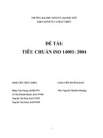
6.2.4.1
Loudspeaker method
Place the loudspeaker outside the building at a distance d from the faỗade with the angle of sound incidence
o
as close as possible to 45 (see Figure 1). Choose the position of the loudspeaker and the distance d to the
faỗade so that the variation of the sound pressure level on the test specimen is minimized. The sound source
is preferably placed on the ground. Alternatively place the sound source as high above the ground as
practically possible. The distance r from the sound source to the centre of the test specimen shall be at least
7 m (d > 5 m) from the faỗade being tested.
Key
1
2
Normal to the faỗade
Vertical plane
3
4
Horizontal plane
Loudspeaker
Figure 1 Geometry of the loudspeaker method
9
© ISO 2004 – All rights reserved
Copyright International Organization for Standardization
Reproduced by IHS under license with ISO
No reproduction or networking permitted without license from IHS
Not for Resale
ISO 10052:2004(E)
--`,,,`,,-`-`,,`,,`,`,,`---
The sound generated shall be steady and have a continuous spectrum in the frequency range considered.
Filters with a bandwidth of one octave band may be used. When using broad-band noise the spectrum of the
sound source may be shaped to ensure an adequate signal-to-noise ratio at high frequencies in the receiving
room.
6.2.4.2
Traffic sound method
The traffic sound method with road traffic as sound source may be used if the sound pressure level is high
enough in relation to the background noise in the receiving room. If the sound is incident on the faỗade from
different directions and with varying intensity, such as road traffic sound in busy streets, the faỗade level
difference is obtained from the average sound pressure levels measured simultaneously on both sides of the
faỗade.
NOTE
6.3
Due to background noise the traffic sound method is normally limited to measure DnT,w < 40 dB.
Measurement of sound pressure levels
6.3.1
Airborne and impact sound insulation between rooms
To determine the insulation against airborne sound,
measure in the source and receiving rooms; to determine
insulation against impact sound, measure only in the
receiving room. In both cases measure the average sound
pressure level in each of the specified octave bands using
an integrating sound level meter. The measurement time
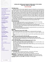
interval shall be approximately 30 s. Stand near the centre
of the floor and face away from the loudspeaker in the
source room or from the separating element in the receiving
room. Hold the sound level meter out at arm's length. Move
o
the microphone four times horizontally through 180 ,
moving the arm up and down in a gentle movement during
the traverse (see Figure 2). Complete the four rotations in a
total time of approximately 30 s. If a parallel octave-band or
real time octave-band sound level meter is not available,
carry out this procedure for each octave band, and read
each Leq for 30 s band level from the meter to obtain an
estimate of the average octave band levels in the room.
Figure 2 — Example for movement of the
sound level meter
The following separating distances are minimum values and shall be exceeded where practicable:
0,5 m between any microphone position and room boundaries;
1,0 m between any microphone position and the sound source.
NOTE
6.3.2
Hearing protectors should be worn by the operator when measuring in the source room.
Airborne sound insulation of faỗades
Place the outdoor microphone at a distance of (2,0 0,2) m from the plane of the faỗade or at such a larger
distance that the distance to the part of the faỗade nearest to the road - for instance the balustrade - is at least
1 m. If the sound source is a loudspeaker measure the outdoor sound pressure level with an integration time
of 30 s and the level in the receiving room according to 6.3.1.
10
Copyright International Organization for Standardization
Reproduced by IHS under license with ISO
No reproduction or networking permitted without license from IHS
© ISO 2004 – All rights reserved
Not for Resale
ISO 10052:2004(E)
If the sound source is the prevailing road traffic, measure the outdoor level and the indoor level simultaneously.
The integration time shall be 60 s and the indoor level is obtained by repeating the procedure of 6.3.1 during
this period. During this measurement period at least 15 vehicles shall have passed.
NOTE
Making sound (e.g. of clothes) should be avoided when moving the sound level meter (Figure 2). Sometimes it
may be necessary to use 3 or 5 fixed positions.
6.3.3
Service equipment sound pressure level
Measure the service equipment sound pressure level in the room directly using a sound level meter. Two fixed
positions are used. One position shall be close to the apparent corner with the acoustically hardest surfaces,
preferably in a distance of 0,5 m from the walls. The second position shall be in the reverberant field of the
room. The distance to any sound source (for example: ventilation outlets) shall be at least 1,5 m.
In each position the measurement time interval shall be chosen in accordance with at least one cycle of the
service equipment working under normal conditions. Use three cycles of the service equipment working under
normal conditions. The operation cycles are given in Annex B.
In order to calculate the average sound pressure level according to equation (14) weight the measurement of
the two microphone positions as follows: Take the measurement at the corner position once and the
measurement in the reverberant field twice.
Frequency range of measurements
The sound pressure levels measured using octave band filters shall cover at least the following midband
frequencies in hertz:
125 Hz 250 Hz
500 Hz
1 000 Hz 2 000 Hz
Sound from service equipment installed is measured in A- or C-weighted sound pressure level with the
specific time weighting.
6.5
Reverberation index data
In the survey method described in this document, the reverberation time (the correction for reverberation time)
may either be based on measurements or estimated with the aid of Table 2 and Table 3.
To make the estimate for unfurnished rooms, Table 2 shall be used to classify the room according to the type
of walls, floor, ceiling and floor covering. Table 3 is then used to find the reverberation index which
corresponds to this classification. For furnished rooms Table 2 can be used directly. Reverberation indices are
given for octave bands, and also for A- and C-weighted sound pressure levels.
Table 3 takes account of room volume, and is valid for rooms typical of those in dwellings. However, it may
also be used for comparable rooms in other types of building.
NOTE 1
The Table is based on a statistical evaluation of reverberation times obtained in dwellings, as typically
constructed in several European countries in the period 1960 to 1980. The standard deviation of the reverberation indices
calculated from these data is approximately 1 dB. Changed construction methods or habitation habits may give rise to
systematic deviations.
Alternatively, the reverberation time may be measured according to the specifications for the survey method
described in ISO/CD 3382-2:2003, 5.2 in octave bands and the reverberation index may be calculated by
using the measured reverberation times according to equation (3). Measurement of reverberation time can be
advantageous if performed only once in a typical room of a building under test which has a large number of
identical rooms (for instance in hotels). For noise measurement of service equipment realised in term of global
weighted level, for calculation of reverberation index k the reverberation time is the average between the data
in the octave bands of 500 Hz, 1 000 Hz and 2 000 Hz.
11
© ISO 2004 – All rights reserved
Copyright International Organization for Standardization
Reproduced by IHS under license with ISO
No reproduction or networking permitted without license from IHS
Not for Resale
--`,,,`,,-`-`,,`,,`,`,,`---
6.4
ISO 10052:2004(E)
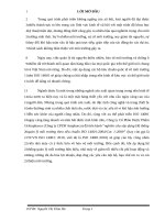
The tabular values of the reverberation indices are listed in Table 3. Table 3 is valid for a reference
reverberation time T0 = 0,5 s and for room sizes of up to 150 m3. Furnished rooms like living rooms, sleeping
rooms and rooms of similar volume and furniture are considered in one group. Furnished kitchens and
bathrooms are considered separately. Concerning unfurnished rooms the reverberation index depends on the
type of construction as listed in Table 2.
Table 2 — List of symbols representing the type of construction
Unfurnished
Floor type
Soft floor covering
Hard floor covering
light
heavy
light
heavy
Light walls/ceiling
a
b
c
d
Heavy walls/ceiling
e
f
g
h
"Light wall" is typically a plasterboard or wooden wall mounted on studs. Heavy walls covered with
plasterboard linings shall be considered as light walls.
--`,,,`,,-`-`,,`,,`,`,,`---
"Heavy wall" is typically a masonry or concrete block wall without lining.
"Light floor" is typically a floor of wooden planks or boards on timber beams.
"Heavy floor" is typically a concrete slab with or without floating concrete covering.
"Floor covering" is typically carpet (soft), tiles or timber flooring (hard).
If the type of construction is not the same throughout the room, but the areas of different construction are
approximately equal, use the average of the values given for the different construction types. For example: if a
room has a heavy floor with a carpet, three heavy walls, one light wall and a light ceiling, use the average of b
and f. If the areas of different construction are not approximately equal, use the value for the type of
construction having the largest area.
NOTE 2
The reverberation indices for A- and C-weighting were derived by averaging the data in the octave bands
between 500 Hz and 2 000 Hz. This method is appropriate in the cases of receiving room levels without strong
components in the low frequency range. This applies to the measurement of broad-band equipment sound spectra.
12
Copyright International Organization for Standardization
Reproduced by IHS under license with ISO
No reproduction or networking permitted without license from IHS
© ISO 2004 – All rights reserved
Not for Resale
Copyright International Organization for Standardization
Reproduced by IHS under license with ISO
No reproduction or networking permitted without license from IHS
© ISO 2004 – All rights reserved
Not for Resale
Volume V in m3
Octave bands in Hz
Furnished rooms
(except bathrooms
and kitchens)
Unfurnished rooms:
type:
a
b
c
d
e
f
g
h
mixed
a+e
type:
b+f
c+g
d+h
Volume V in m3
Octave bands in Hz
Furnished rooms:
kitchens
bathrooms
others
Unfurnished rooms:
type:
a
b
c
d
e
f
g
h
Mixed
a+e
type:
b+f
c+g
d+h
0,5
2
3,5
3,5
3,5
4
4,5
5
5,5
3
4
4,5
4,5
1
2
1,5
1,5
4
4,5
4,5
5
2,5
3,5
3
3,5
3,5
3,5
3,5
3
2
2
0,5
1
2,5
2,5
2,5
3,5
4,5
4
4,5
2,5
0
1
0
0
3,5
4,5
3,5
4
2
250
0
1
0
0
1
0
125
250
125
4,5
5
5
2
4
4,5
4
4,5
4,5
5,5
6
3,5
0,5
500
4
4
4
1
3
3,5
3
3,5
4,5
4,5
5
2,5
0
0
- 0,5
500
4
5,5
5
1,5
3,5
5
5
4
4
5,5
5
3
0
1 000
35 ≤ V < 60
3
4,5
4,5
1
2,5
4
4
3,5
3,5
5
5
2,5
0
0
- 0,5
1 000
V < 15
3
5
5,5
1
2,5
4,5
5
2,5
3
5,5
5,5
2
0
2 000
2,5
4,5
4,5
0
2
4
4
1,5
2,5
5
4,5
1
0
-0,5
-1
2 000
4
5,5
5,5
1,5
3
5
5
4
5
5,5
5,5
3
0
A, C
3
4,5
4,5
0,5
2
4
4
3,5
3,5
5
5
2
0
0
- 0,5
A, C
3,5
3,5
4
1
2,5
2
2
4
4,5
5
5,5
2,5
0,5
125
3
2,5
3
1
1
1
1
3,5
4,5
4
4,5
2,5
0
1,5
0
125
4,5
5
5
2,5
4
4
4
4
5
5,5
6
3,5
0,5
250
4
4
4
1,5
3
3
3
4
4,5
5
5
3
0,5
1,5
0
250
3,5
5
5
1
3
4,5
4,5
4
4
5
5,5
2,5
0
0,5
0
1 000
5
5,5
5,5
2,5
4,5
5
4,5
5
5
6
6,5
4
0,5
500
4
6
5,5
2
3,5
5,5
5,5
4,5
4
6
5,5
3,5
0,5
1 000
60 ≤ V < 150
4
4,5
4,5
1,5
3,5
4
3,5
4
4,5
5
5,5
3
0
0,5
0
500
15 ≤ V < 35
3
5,5
6
1,5
2,5
5
5,5
3
3
6
6
2,5
0
2 000
3
4,5
4,5
0,5
2,5
4
4
2
3
5
5
1,5
0
0
- 0,5
2 000
Table 3 — Reverberation index data in dB in octave bands and corresponding to A- or C-weighted sound pressure levels
4,5
6
6
2
3,5
5,5
5,5
4,5
5
6
6
3,5
0,5
A, C
3,5
5
5
1
2,5
4,5
4,5
4
4
5,5
5
2,5
0
0,5
0
A, C
ISO 10052:2004(E)
--`,,,`,,-`-`,,`,,`,`,,`---
13
ISO 10052:2004(E)
6.6
Precision
It is required that the measurement procedure gives satisfactory reproducibility. This can be determined in
accordance with the method shown in EN 20140-2 and shall be checked from time to time, particularly when a
change is made in procedure or instrumentation.
NOTE
Numerical requirements for reproducibility of the engineering methods for airborne and impact sound
insulation are given in EN 20140-2. It is estimated that the results from the survey test method and the corresponding
engineering method differ within ± 2 dB.
7.1
Expression of results
Airborne sound insulation
For the statement of the airborne sound insulation, the values of the standardized level difference DnT, the
normalized level difference Dn or the apparent sound reduction index R´, R´45°, R´tr,s shall be given at all
frequencies of measurement, to one decimal place, in tabular form and in the form of a curve. Graphs in the
test report shall show the value in decibels plotted against frequency on a logarithmic scale, and the following
dimensions shall be used:
15 mm for an octave band;
20 mm for 10 dB.
The use of a form in accordance with Annex A is preferred. Being a short version of the test report it shall
include all information of importance regarding the test object, the test procedure and the test results.
For the evaluation of single-number ratings from the octave-band results, see EN ISO 717-1. It shall be clearly
stated that the evaluation has been based on a result obtained by a field survey method.
7.2
Impact sound insulation
For the statement of the impact sound insulation, the values of the standardized impact sound pressure level
L’nT or the normalized impact sound pressure level L’n shall be given at all frequencies of measurement, to
one decimal place, in tabular form and in the form of a curve. Graphs in the test report shall show the value in
decibels plotted against frequency on a logarithmic scale, and the following dimensions shall be used:
15 mm for an octave band;
20 mm for 10 dB.
The use of a form in accordance with Annex A is preferred. Being a short version of the test report it shall
include all information of importance regarding the test object, the test procedure and the test results.
For the evaluation of single-number ratings from the octave-band results, see EN ISO 717-2. It shall be clearly
stated that the evaluation has been based on a result obtained by a field survey method.
7.3
Service equipment sound pressure level
For the statement of the sound pressure level from housing service equipment quantities given in Table 1
shall be given A- or C-weighted rounded to one dB.
Being a short version of the test report it shall include all information of importance regarding the test object,
the test procedure and the test results.
14
Copyright International Organization for Standardization
Reproduced by IHS under license with ISO
No reproduction or networking permitted without license from IHS
© ISO 2004 – All rights reserved
Not for Resale
--`,,,`,,-`-`,,`,,`,`,,`---
7