Ch5 1 v1 TRUYỀN SỐ LIỆU VÀ MẠNG
Bạn đang xem bản rút gọn của tài liệu. Xem và tải ngay bản đầy đủ của tài liệu tại đây (625.82 KB, 36 trang )
Chapter 5
Analog Transmission
5.1
Copyright © The McGraw-Hill Companies, Inc. Permission required for reproduction or display.
5-1 DIGITAL-TO-ANALOG CONVERSION
Digital-to-analog conversion is the process of
changing one of the characteristics of an analog
signal based on the information in digital data.
Topics discussed in this section:
Aspects of Digital-to-Analog Conversion
Amplitude Shift Keying
Frequency Shift Keying
Phase Shift Keying
Quadrature Amplitude Modulation
5.2
Digital to Analog
Conversion
5.3
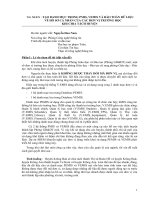
Digital data needs to be carried
on an analog signal.
A carrier signal (frequency fc)
performs the function of
transporting the digital data in
an analog waveform.
The analog carrier signal is
manipulated to uniquely identify
the digital data being carried.
Figure 5.1 Digital-to-analog conversion
5.4
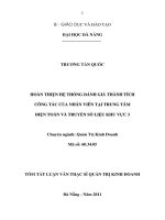
Figure 5.2 Types of digital-to-analog conversion
5.5
Note
Bit rate, N, is the number of bits per
second (bps). Baud rate is the number
of signal
elements per second (bauds).
In the analog transmission of digital
data, the signal or baud rate is less than
or equal to the bit rate.
S=Nx1/r bauds
Where r is the number of data bits per
signal element.
5.6
Example 5.1
An analog signal carries 4 bits per signal element. If
1000 signal elements are sent per second, find the bit
rate.
Solution
In this case, r = 4, S = 1000, and N is unknown. We can
find the value of N from
5.7
Example 5.2
An analog signal has a bit rate of 8000 bps and a baud
rate of 1000 baud. How many data elements are
carried by each signal element? How many signal
elements do we need?
Solution
In this example, S = 1000, N = 8000, and r and L are
unknown. We find first the value of r and then the value
of L.
5.8
Amplitude Shift Keying
(ASK)
5.9
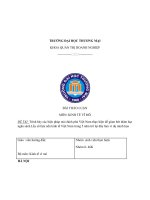
ASK is implemented by changing the
amplitude of a carrier signal to
reflect amplitude levels in the digital
signal.
For example: a digital “1” could not
affect the signal, whereas a digital
“0” would, by making it zero.
The line encoding will determine the
values of the analog waveform to
reflect the digital data being carried.
Bandwidth of ASK
5.10
The bandwidth B of ASK is
proportional to the signal
rate S.
B = (1+d)S
“d” is due to modulation and
filtering, lies between 0 and
1.
Figure 5.3 Binary amplitude shift keying
5.11
Figure 5.4 Implementation of binary ASK
5.12
Example 5.3
We have an available bandwidth of 100 kHz which
spans from 200 to 300 kHz. What are the carrier
frequency and the bit rate if we modulated our data by
using ASK with d = 1?
Solution
The middle of the bandwidth is located at 250 kHz. This
means that our carrier frequency can be at fc = 250 kHz.
We can use the formula for bandwidth to find the bit rate
(with d = 1 and r = 1).
5.13
Example 5.4
In data communications, we normally use full-duplex
links with communication in both directions. We need
to divide the bandwidth into two with two carrier
frequencies, as shown in Figure 5.5. The figure shows
the positions of two carrier frequencies and the
bandwidths. The available bandwidth for each
direction is now 50 kHz, which leaves us with a data
rate of 25 kbps in each direction.
5.14
Figure 5.5 Bandwidth of full-duplex ASK used in Example 5.4
5.15
Frequency Shift Keying
5.16
The digital data stream
changes the frequency of the
carrier signal, fc.
For example, a “1” could be
represented by f1=fc +f, and
a “0” could be represented by
f2=fc-f.
Figure 5.6 Binary frequency shift keying
5.17
Bandwidth of FSK
5.18
If the difference between the
two frequencies (f1 and f2) is
2f, then the required BW B
will be:
B = (1+d)xS +2f
Example 5.5
We have an available bandwidth of 100 kHz which
spans from 200 to 300 kHz. What should be the carrier
frequency and the bit rate if we modulated our data by
using FSK with d = 1?
Solution
This problem is similar to Example 5.3, but we are
modulating by using FSK. The midpoint of the band is at
250 kHz. We choose 2Δf to be 50 kHz; this means
5.19
Coherent and Non
Coherent
5.20
In a non-coherent FSK scheme,
when we change from one frequency
to the other, we do not adhere to
the current phase of the signal.
In coherent FSK, the switch from
one frequency signal to the other
only occurs at the same phase in
the signal.