Api rp 550 1 11 1981 scan (american petroleum institute)
Bạn đang xem bản rút gọn của tài liệu. Xem và tải ngay bản đầy đủ của tài liệu tại đây (681.26 KB, 12 trang )
Manual on Installation of Refinery
Instruments and Control Systems
Part 1-Process Instrumentation and Control
Section 11-Eiectrical Power Supply
Refining Department
API RECOMMENDED PRACTICE 550
THIRD EDITION, JUNE 1981
OFFICIAL PUBLICATION
REG. U.S. PATENT OFFICE
CONTENTS
SECTION II-ELECTRICAL POWER SUPPLY
PAGE
11.1 Scope ...................................................... .
11.2 General ..................................................... .
11.2.1 Plant Power Reliability. . . . . . . . . . . . . . . . . . . . . . . . . . . . . . . . . . . . . .
11.2.2 Power Outage . . . . . . . . . . . . . . . . . . . . . . . . . . . . . . . . . . . . . . . . . . . .
11.3 Instrument Load Characteristics . . . . . . . . . . . . . . . . . . . . . . . . . . . . . . . . . .
11.3.1 Pneumatic Systems. . . . . . . . . . . . . . . . . . . . . . . . . . . . . . . . . . . . . . . . .
11.3.2 Electronic Analog Systems . . . . . . . . . . . . . . . . . . . . . . . . . . . . . . . . . .
11.3.3 Digital Systems . . . . . . . . . . . . . . . . . . . . . . . . . . . . . . . . . . . . . . . . . . .
11.4 Instrument Load Requirements . . . . . . . . . . . . . . . . . . . . . . . . . . . . . . . . . . .
11.4.1 General . . . . . . . . . . . . . . . . . . . . . . . . . . . . . . . . . . . . . . . . . . . . . . . . . .
11.4.2 Reliability Requirements . . . . . . . . . . . . . . . . . . . . . . . . . . . . . . . . . . . .
11.4.3 Power Quality Requirements.... . . . . . . . . . . . . . . . . . . . . . . . . . . . . .
11.4.4 Emergency Power Source Capacity . . . . . . . . . . . . . . . . . . . . . . . . . . .
11.5 Electrical Power Supply . . . . . . . . . . . . . . . . . . . . . . . . . . . . . . . . . . . . . . . .
11.5.1 General . . . . . . . . . . . . . . . . . . . . . . . . . . . . . . . . . . . . . . . . . . . . . . . . . .
11.5.2 Conditions. . . . . . . . . . . . . . . . . . . . . . . . . . . . . . . . . . . . . . . . . . . . . . . .
11.5.3 Instrument Power Supply Source. . . . . . . . . . . . . . . . . . . . . . . . . . . . . .
11.5.4 Power Supply Regulation..................... . . . . . . . . . . . . . . .
11.5.5 Pneumatic System Power Supplies . . . . . . . . . . . . . . . . . . . . . . . . . . . .
11.5.6 Electronic System Power Supplies . . . . . . . . . . . . . . . . . . . . . . . . . . . .
11 .5. 7 Typical Designs . . . . . . . . . . . . . . . . . . . . . . . . . . . . . . . . . . . . . . . . . . .
11.6 Automatic Transfer and Parallel Power Sources . . . . . . . . . . . . . . . . . . . . .
11.6.1 General . . . . . . . . . . . . . . . . . . . . . . . . . . . . . . . . . . . . . . . . . . . . . . . . . .
11.6.2 Design Problems. . . . . . . . . . . . . . . . . . . . . . . . . . . . . . . . . . . . . . . . . . .
11.6.3 Problem Areas . . . . . . . . . . . . . . . . . . . . . . . . . . . . . . . . . . . . . . . . . . . .
11.7 Distribution System . . . . . . . . . . . . . . . . . . . . . . . . . . . . . . . . . . . . . . . . . . . .
11.7. 1 General . . . . . . . . . . . . . . . . . . . . . . . . . . . . . . . . . . . . . . . . . . . . . . . . . .
11.7 .2 Requirements . . . . . . . . . . . . . . . . . . . . . . . . . . . . . . . . . . . . . . . . . . . . .
11.7. 3 Criteria for System Design . . . . . . . . . . . . . . . . . . . . . . . . . . . . . . . . . .
11. 8 Wiring Methods . . . . . . . . . . . . . . . . . . . . . . . . . . . . . . . . . . . . . . . . . . . . . . .
11.8.1 General . . . . . . . . . . . . . . . . . . . . . . . . . . . . . . . . . . . . . . . . . . . . . . . . . .
11.8.2 Power Wiring . . . . . . . . . . . . . . . . . . . . . . . . . . . . . . . . . . . . . . . . . . . . .
11.8. 3 Special Procedures . . . . . . . . . . . . . . . . . . . . . . . . . . . . . . . . . . . . . . . .
11.9 System and Equipment Grounding . . . . . . . . . . . . . . . . . . . . . . . . . . . . . . . .
11.9 .1 Instrument Signal Grounding. . . . . . . . . . . . . . . . . . . . . . . . . . . . . . . . .
11.9.2 Instrument Power Supply Grounding . . . . . . . . . . . . . . . . . . . . . . . . . .
11.9. 3 Equipment Grounding . . . . . . . . . . . . . . . . . . . . . . . . . . . . . . . . . . . . . .
vii
I
2
2
2
2
2
3
3
3
4
4
4
4
4
5
5
5
5
6
7
7
7
7
8
8
8
8
9
9
9
9
9
9
9
9
LIST OF ILLUSTRATIONS
Figures
Il-l-Secondary Transfer Using Circuit Breakers. . . . . . . . . . . . . . . . . . . . . . .
11-2-Fuel Supply Shutdown Circuit for Momentary Power Failure Security.
11-3-Power Supply for Critical Instrument Load. . . . . . . . . . . . . . . . . . . . . . .
11-4-Typical Automatic Transfer Switching Methods . . . . . . . . . . . . . . . . . . .
11-5-Semi-Critical Supply . . . . . . . . . . . . . . . . . . . . . . . . . . . . . . . . . . . . . . . . .
11-6-Critical Power Supply . . . . . . . . . . . . . . . . . . . . . . . . . . . . . . . . . . . . . . . .
11-7-Critical Power Supply with Redundancy . . . . . . . . . . . . . . . . . . . . . . . .
viii
I
2
3
4
6
7
8
Part !-Process Instrumentation and Control
SECTION 11-ELECTRICAL POWER SUPPLY
11.1
Scope
This section is intended as a guide for the design and selection of equipment for a highly reliable electrical power
distribution system for plant process instrumentation and
controls. For additional information on the installation of
electrical systems, refer to API RP 540, Recommended
Practice for Electrical Installations in Petroleum Processing Plants.
11.2
General
A supply of continuous electrical power to a plant
process instrumentation and control system is essential ror
safe operation and the manufacture of on-grade products.
When power interruptions occur, the plant must be designed either to continue to operate on standby steamdriven turbines or to shut down in a safe and orderly manner. Control systems and monitoring devices must
continue to provide information and control during this
period; therefore, the electrical power system reliability requirement is much greater for instrument system supplies.
11.2.1
PLANT POWER RELIABILITY
The reliability of the service to a plant depends on many
factors. Utility companies invest considerable time and effort in improving the reliability of their systems. This includes providing redundant equipment, alternate sources of
power such as neighboring electrical utilities, and various
contingency plans to permit operation during emergency
conditions.
The reliability of electric power varies from region to re-
ELECTRIC UTILITY SYSTEM
ELECTRIC UTILITY SYSTEM
/
-
INTERLOCK
I
I
Ill 11111"111
/INTERLOCKS
(---'----~---)
( __ J __ )
LOADS
gion, and in most areas seasonal outages are predictable.
Unpredicted events, such as earthquakes or man-caused
disasters, also cause long, unexpected outages or curtailments.
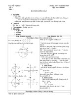
The configuration of the transmission and distribution
system can be arranged to provide maximum reliability.
For an all-electric-drive plant where service is critical, at
least one redundant feeder line is required together with
transformers, main breakers, and a tie-breaker for fast automatic transfer. Typical utility substation arrangements
are shown in Figure 11-1.
If the plant has sufficient steam and electric operation is
only a matter of economics, then a single utility feed could
be used with steam-driven turbines to back up electric motors. Most utility companies will provide whatever configuration the customer requires. In return for this service, a
facilities charge may be added to the monthly billing for
any electrical equipment which exeeds what the utility
company considers necessary for standard service.
The trend in the processing industry is to rely more
heavily on the utility company's ability to deliver power
with minimal, if any, interruption. New plants are relying
Jess on uneconomical standby steam drivers, especially in
locations where the utility has a reliable service record.
As a result, only the critical services, such as essential
digital and analog control systems and shutdown circuits,
are being served with uninterruptible power supplies in
new installations. The processing portion of the plant is
left to circulate down as much as possible by using criticalstandby steam drivers (generally on circulating pumps)
when power failures occur.
I
:TIE
BUS 1-.......-~.................---~
I -----~-- BUS 2
BUS
LOADS
LOADS
Figure 11-1-Secondary Transfer Using Circuit Breakers
2
11.2.2
PART I-PROCESS INSTRUMENTATION AND CONTROL
POWER OUTAGE
A utility finds it virtually impossible to provide constant
voltage and frequency power to its customers because of
power outages resulting from incidents such as automobiles hitting transmission poles, dirty insulators flashing
over, falling lines, lightning surges, and operating switching surges.
By utility-company definition, a power outage occurs
when its system voltage and frequency fall to zero for a
one-cycle time duration. Voltage dips and frequency slowdowns are considered system disturbances, except during
power outages. In either case, critical loads such as digital
control systems or computers would be severely upset or
go off line if no electrical system backup is available.
Some digital systems require that input voltage never
exceed precise limits of nominal voltage while other systems may sustain an outage lasting as long as 30 milliseconds before shutting down. The degree of voltage-cycle
variation tolerance for a specific critical load, such as a
computer, a shutdown system, or a digital temperature indicator, is generally only a few volts or cycles. When the
electrical supply approaches the voltage limits or partialcycle variation, the critical load is in trouble.
11.3
11.3.1
Instrument Load Characteristics
PNEUMATIC SYSTEMS
Where pneumatic control systems are used for plant
process control, the electrical requirements can usually be
supplied from a relatively simple electrical system. Instru-
ments in service together with pneumatic control systems
that require electrical power are multipoint temperature indicators, recorders, annunciators, shutdown circuits, and
various process trips. These devices may not require
closely regulated voltage, frequency, and harmonic content
characteristics. Special attention will be required for devices such as flame monitors, dropout valves, or solenoids
that may require a no-break electrical supply.
11.3.2
ELECTRONIC ANALOG SYSTEMS
Electronic analog systems may receive alternating current (ac) directly and convert to direct current (de) internally, or receive de directly from a common de power supply. In most electronic controllers, even a momentary loss
of power may bump the output and cause disturbances in
the process. During total power failure and plant shutdown, backup must be provided to the instruments long
enough to bring the plant down in an orderly and safe
manner.
11.3.3
DIGITAL SYSTEMS
The use of digital systems for monitoring, supervising,
or controlling is becoming more common. The power supply requirements, listed in the respective supplier system
installation manual, must be followed closely. This usually
requires no-break power with closely regulated voltage,
frequency, and harmonic content. The designers of the
power supply must consider the control system transient
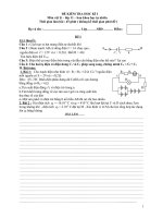
and steady state conditions and must provide suitable isolation to prevent noise scattering from component to component. In most cases, purchased utility power or in-plant
MANUAL OR
AUTOMATIC
SHUTDOWN DEVICE
POWER
.-----------~---!..!~-+-- SUPPLY
THREE WAY
SOLENOID
VALVE--------
.
ENERGIZED FLOW
BACK PRESS
REGULATOR
(REVERSE
HOOKUP)
ORIFICE
VENT
VOLUME BOTTLE
A.O.
FUEL TO GAS OR
OIL BURNER
Figure 11-2-Fuel Supply Shutdown Circuit for Momentary Power Failure Security
SECTION 11-ELECTRICAL POWER REQUIREMENTS FOR INSTRUMENTATION
generated power will not satisfy these requirements and a
special system must be provided.
11.4
Instrument Load Requirements
11.4.1
GENERAL
The power supplies for control, alarm, and shutdown
systems can be grouped into different categories depending
on whether the system is required during power outages or
disturbances. Frequently this is determined by whether the
service is control or non-control. In general, control loops
are those which operate modulating valves, on-off devices
or directly control equipment such as motors and turbines
in the performance of shutdown circuits. Non-control
loops can be indicators, recorders, annunciators, certain
analyzers, and so forth. Careful consideration must be
given to the type and service of each control device so that
its power reliability requirements are met. Operational requirements during both normal and emergency conditions,
such as a plant or unit power failure, will also dictate
power reliability requirements.
11.4.2
3
ditions but can operate satisfactorily through short interruptions. An independent power supply source that is separate from the utility is required during power outages (see
Figure 11-4). Semi-critical loads may be further categorized into loads for which interruptions of the ac supply as
long as 0.2 second are permitted and those for which interruptions as long as 20 seconds may be permitted. The typical control loop is in the first category; the noncontrol
loop-recorders, indicators, annunciator systems, and so
forth-is in the second. Faster transfer from normal to
standby power, using electromechanical ( contactor)
switches which have approximately a 100 millisecond
switching time, is required for the first category. Usually,
the normal plant power system delayed transfer of startup
of standby generators is sufficient for noncontrol instruments.
LINE
CONSTANT VOLT AGE
TRANSFORMER .-::----1-----.
RELIABILITY REQUIREMENTS
CVT
Reliability requirements are determined by the need for
the device to function during power interruptions. The permissible interruption times are used to illustrate the categories. These times will vary according to control equipment
characteristics. For instance, it is possible that use of a delayed dropout provision as shown in Figure 11-2 in a control loop would shift it from a "critical" to "semicritical" supply. Typical categories are listed in 11.4.2.1
through 11.4.2.3.
)
STATIC SWITCH
11.4.2.1
Critical
A critical load is a control system that is essential for
normal and emergency operation and that cannot tolerate a
power outage greater than approximately 4 milliseconds.
Critical loads require sources which are independent of the
normal plant power supply. Alternating current loads may
be supplied by a static uninterruptible power supply (UPS)
or a rotating motor-generator set with a high inertia flywheel. Transfer of supply from a normal to a standby
source requires solid state static switches that have essentially zero switching time (see Figure 11-3). Direct current
loads can be supplied by battery-backed de power supplies. The transfer of de from a normal to a standby source
requires solid state diodes or silicon controlled rectifiers
that also have essentially zero switching time.
11.4.2.2
Semi-Critical
Semi-critical loads must operate during emergency con-
LOAD
NoTES:
l. Select branch circuit fuses to coordinate with SCR fuses in inverter.
2. Stored energy in CVT provides power during part of transfer time
to minimize the interruption. Redundancy may be required for reliability.
3. On an overload or short-circuit, the CVT output voltage typically
drops rapidly toward zero and at short-circuit, the output current is
limited to approximately 150 percent of rated value. uninterrupted
power supply systems typically bypass via the solid state switch to
the "stiffer" alternate line on overloads and short-circuits. Use of a
CVT in alternate line could cause problems with protective device
(fuse or circuit breaker) operation and proper clearing of branch circuit overload or short-circuit.
Figure 11-3-Power Supply for Critical Instrument
Load
PART I-PROCESS INSTRUMENTATION AND CONTROL
4
EMERGENCY
SOURCE
LOCAL
GENERATOR
ELECTRIC UTILITY
ELECTRIC
UTILITY
9
~L f~~
Trrr T1r1
CRITICAL LOADS
CRITICAL LOADS
NONCRITICAL
LOADS
Figure 11-4-Typical Automatic Transfer Switching Methods
11.4.2.3
Non-Critical
Tank gaging systems and process quality analyzers are
examples of non-critical loads that may be dropped during
a power outage without affecting safe and orderly emergency operations. However, the power supply during normal operating conditions must have a high degree of reliability.
11.4.3
POWER QUALITY REQUIREMENTS
Quality grading will group loads according to the requirements of the control devices to ensure that realistic
and not excessive limits are placed on supply fluctuations.
Typical grading limits are as follows:
For ac loads:
Voltage regulation
Frequency regulation
Total harmonic
distortion
For de loads:
Voltage regulation
Voltage ripple
11.4.4
inverter systems. When longer periods are required or requirements exceed about 20 kilovolt-amperes, rotating
equipment sources may be more economical.
Certain control system devices such as digital control
systems with heavily filtered power supplies, or high speed
disc storage devices, will have very high inrush currents
when energized. In some instances, fast transfer solid state
switches have sensed the high inrush currents and attendant voltage drop and then transferred loads that should not
have been transferred. Consideration must be given to
these design problems to minimize voltage or frequency
variations during high inrush.
11.5
Electrical Power Supply
± 2 percent
± 1 hertz for 50160 hertz
11.5.1
GENERAL
systems
5 percent maximum
The power supply for process control systems must be
designed to the following criteria:
±I percent
Y2 percent maximum
EMERGENCY POWER SOURCE
CAPACITY
An important aspect of load requirements is the length
of time the particular load must function during abnormal
or emergency power supply conditions. Loads can be divided into categories to determine the required capacity for
standby power sources. A 1-hour period may be adequate
for some; an 8-hour period for others; still others may require longer periods. Capacities for periods of 2 minutes to
8 hours are commonly available for rectifier-battery-
I. Provision must be made for a reliable supply, meeting
the required voltage, frequency, and harmonic characteristics, during all normal and abnormal plant operating conditions.
2. For plant emergency conditions, such as loss of steam
or power, reliable power must be provided for the period
required to put the plant in a safe holding condition or to
shut down safely.
11.5.2
CONDITIONS
The power supply shall be designed to handle such conditions as:
1. Momentary interruptions to plant power supply.
2. Extended outages of plant power supply.
3. Abnormal or transient conditions incompatible with
quality requirements of process control loads.
SECTION 11-ELECTRICAL POWER REQUIREMENTS FOR INSTRUMENTATION
4. Internal faults in the process control system.
5. Isolation of major components of the process control
power system without unacceptable load interruptions.
11.5.3
INSTRUMENT POWER SUPPLY SOURCE
The instrument power supply should be isolated from
other loads. A separate transformer fed directly from the
essential loads bus is recommended. When two independent buses are available, an automatic transfer switch
should be used to improve continuity. The transformer
should have taps on both the primary and secondary windings to permit compensation for prolonged voltage variations. The transformer should be located as close to the instruments as practical, preferably within 100 feet.
11.5.4
5
4. Uninterruptible Power Supplies (UPS). A UPS is the
first device in this listing that not only smooths voltage
fluctuations to the instrument load but also maintains a
load under longer term outage (blackout) conditions. The
key components of UPS systems are an ac to de rectifier/
battery charger, storage batteries, a de to ac inverter, and a
static transfer switch (see Figure 11-4 ). A UPS allows the
user either to shut down critical loads in an orderly fashion
or to transfer to onsite power generation equipment as described below.
UPS systems normally are designed to provide from 15
to 30 minutes of support. Beyond this, it becom~s uneconomical to increase the battery capacity. This is also about
as long as electronic instruments and computers can safely
run without air conditioning. (Most uninterruptible power
supplies do not support a computer's environmental system.)
POWER SUPPLY REGULATION
Utility companies have lost system capacity from catastrophic failures in generation or transmission systems that
resulted in long periods of reduced voltage to the customer. Such periods are commonly known as brownouts.
If a utility is voltage-regulated, then it will move service
from grid to grid for short periods. This system is known
as rotating blackouts. When motors are started, lines are
switched, and so forth, poor voltage regulation within the
plant can cause isolated local brownouts or voltage fluctuations.
Several types of regulation systems are available which
give increasing amounts of protection against voltage fluctuations. The uninterruptible power supply, which is recommended for many process control applications, protects
against both voltage .fluctuations and power outages. Simpler voltage regulators may be suitable for some of the less
critical installations.
The following is a list of the types of power regulation
systems available and the amount of protection they afford:
1. Motor-Generator Sets. Motor-generator sets use mechanical inertia to ''ride through'' in case of a power interruption. Ride-through capabilities can be provided for periods from 300 milliseconds.. to several seconds. This
provides protection against transients but not against
brownouts or blackouts.
2. Line Conditioners. These are electronic analogs of motor-generator sets. They can react to transients as short as
several milliseconds and afford protection under brownout
conditions.
3. Voltage Regulators. These are usually either constant
voltage transformers or electronic-magnetic regulators
which have a response time of approximately 100 milliseconds. In addition to smoothing out incoming power, they
can compensate for brownouts.
11.5.5
PNEUMATIC SYSTEM POWER SUPPLIES
Generally, the electrical components of a pneumatic analog control system can be satisfactorily supplied from the
normal plant power system assuming that this system has
normal and alternate sources which are reasonably independent of each other. This independence should be maintained in providing normal and alternate supplies to the
main distribution bus of the process control power system.
When the plant has only a simple radial supply, some provision should be made for an alternate supply to the
process control system main bus. In all cases, particular attention must be paid to the requirements of critical circuits
and components. Examples of these are the boiler plant
control, safety devices and associated circuits, compressor
control and shutdown circuits, and critical motor-operated
valves which must function after total power failure. Special provisions, such as emergency generator sets or battery-inverter combinations, may be required.
11.5.6
ELECTRONIC SYSTEM POWER
SUPPLIES
The electronic analog control and digital monitoring and
control systems impose much more stringent requirements
on the power supply system. Independent normal and alternate supply sources to main ac and de distribution buses
are required. In most plants, it will be necessary to provide
an independent generation source in the form of an enginegenerator, turbine-generator, motor-turbine-generator set,
rectifier-battery-inverter (UPS), or a combination to serve
as one source. Where stringent supply quality requirements
are applicable, the generation source may serve as the normal supply. Particular attention must be paid to determine
PART I-PROCESS INSTRUMENTATION AND CONTROL
6
to what extent the supply from the plant power system can
serve as the alternate source. By applying the reliability
and quality requirements and degree of redundancy which
must be provided, the capacity of independent generation
can be held to an economic minimum.
Distributed control and monitoring systems used in petrochemical process control have a computer operating as
the heart of the system. These devices, with memory
storage and large-scale integrated circuits, are very susceptible to low voltage deviations and shut down rapidly if
this occurs. This protects information that is in the memory from being improperly modified and possibly causing
an erroneous operation or data shortage. An uninterruptible power supply is highly desirable to buffer out voltage
dips and transients and minimize nuisance shutdowns.
Cathode-ray tubes, disk-storage devices, high-speed
printers, and other peripherals are also very sensitive to
voltage and frequency variations and should be isolated by
separate transformers and buffered by an uninterruptible
power supply.
There are several design problems to consider for a
backup power supply for a computer system. Computersystem power supplies are heavily filtered and have a high
inrush on startup, which has been measured as high as 10
times the normal circuit load on some systems. The
backup power supply which may be a rotating motorgenerator set or uninterruptible power supply, must be designed to supply this current inrush, or a bypass system
must be provided to supply power fr~m the alternate
source for startup. Computers on process control may be
started around the clock, and for this installation it is generally better to have a backup that can supply the starting
current.
Another possible problem is a distorted sine wave output
from the uninterruptible power supply. Most uninterruptible power supplies have inherently higher impedances
than the critical load to which they are connected. If the
mismatch is severe, a distorted wave form and poor power
factor result. Distortion, or high harmonic content, in the
ac power supply can cause unusual disturbances in the operation of a digital device.
Isolation transformers generally contribute to the mismatch. The normal solution is to change the firing-phase
angle of the inverter silicon controlled rectifier. This
should be done by the uninterruptible power supplier after
the system is running with a full load.
For digital systems, installation manuals should be obtained and a site survey conducted with the supplier's customer engineer to discuss all aspects of the installation.
nature of the load being supplied. Simple devices like coils
or solenoid valves can be held in for short durations with
diodes, capacitors, and variable resistors. Complicated
electronic systems may require a more sophisticated
backup, the ultimate being an uninterruptible power supply.
A diesel engine or steam-turbine-driven emergency generator can be used. These generators vary in size from 5
kilowatts to 250 kilowatts, with single or three phases and
voltages up to 480 volts. Larger generators with higher
voltages are available and can be driven with gas turbines
or diesel engines.
Steam turbines driving emergency generators are kept
on standby by bypassing a fast-opening control valve with
enough steam to keep the turbine hot. When a power failure occurs, the control valve opens and brings the turbine
rapidly up to speed to provide the backup power. This requires up to 1 minute and often the governor will trip the
turbine on overspeed before it can recover and bring the
turbine back to synchronous speed. The turbine-generator
should be tested frequently by stroking the control valve
and actuating the governor to ensure that it will operate
properly when needed.
A more satisfactory method is to operate steam-turbine
emergency generators continuously at synchronous speed
with a light load. When a power failure occurs, the critical
load is transferred by an automatic transfer switch in as
few as seven cycles to the emergency generator. This arrangement is possible because of new developments in turbine technology. When a governor valve controls an unloaded turbine, the valve is almost pinched off and hard
seat material now available must be specified to prevent
"wire drawing." Wire drawing is defined as erosion of the
r------EMERGENCY
GENERATOR
[
-~AUTOMATIC
TRANSFER
The degree of electrical system backup depends on the
SWITCH
-~----+-----,-
CRITICAL BUS
(FUSES)
INSTRUMENT
11.5. 7 TYPICAL DESIGNS
UTILITY
CONTROL
EMERGENCY
LIGHTING
Figure 11-5-Semi-Critical Supply
SECTION 11-ELECTRICAL POWER REQUIREMENTS FOR INSTRUMENTATION
seat, accelerated by the high steam velocities through the
narrow valve opening. Also a National Electrical Manufacturers Association Class D governor should be specified,
as a minimum. This is a precision hydraulic governor that
maintains very precise control on the turbine speed from
no-load to full-load condition. This Class D governor is
necessary to provide suitable frequency and voltage stability.
If the critical load requires continuous power, an uninterruptible power supply may be required. This device operates with battery power and supplies continuous ac
power to critical loads. It inverts the de battery voltage to a
square wave and usually smooths and filters the output to
an ac voltage with less than 5 percent harmonic distortion.
The batteries are charged by battery rectifiers from the ac
normal or standby power.
Since an uninterruptible power ·supply is very complex
equipment with many electronic components, it may have
a mean time between failure that is less than the serving
utility. Therefore, design of the installation must be carefully planned to provide a bypass or proper backup with
greater reliability than the utility service. During installation of an uninterruptible power supply, various arrangements can be made to accomplish this.
One arrangement provides two 100 percent capacity uninterruptible power supplies tied to the critical bus. Another arrangement uses a static switch to transfer the critical load off the uninterruptible power supply when a
failure occurs. Transfer times of Y4 microsecond are common for static switches. They can detect uninterruptible
power supply failure and switch to bypass before the critical load is affected. For maintenance purposes, a makebefore-break manually operated bypass switch should be
provided to completely bypass the uninterruptible power
supply and static switch.
Typical one-line diagrams of power supply arrangements and a power conditioning and distribution system
are shown in Figures ll-5, ll-6, and ll-7. Each process
plant requires a design uniquely suited to its particular load
requirements.
11.6
Automatic Transfer and Parallel
Power Sources
11.6.1
GENERAL
In all cases where normal and alternate sources are provided, a means of automatic transfer between the sources
or parallel operation is required. Reliability criteria will establish those loads that require rapid solid-state switching
and those for which elec(romechanical switching is acceptable. Solid-state switching costs may triple the cost of
electromechanical switching.
7
UTILITY
EMERGENCY
GENERATOR
-~
t
~~
AUTOMATIC
TRANSFER
~SWITCH
+
)
M
) CIRCUIT BREAKERS
L
TRANSFORMER
)-Q-T- -l
I
I
I
I
I
I
I
I
A
o---t-Ov
MANUAL OPEN
'\. A
!';j
MOTOR-OPERATED
BREAKER
)
....,----'----+------,--
CR I Tl CAL BUS
CURRENTLIMITING FUSE
INSTRUMENT
CONTROL
COMPUTER
NoTEs:
I. V-The voltage detector senses 90 percent.
2. A-Ampere sensor. If 150 percent is full load current, the uninterruptible power supply goes to limit mode.
3. UPS-Voltage output drops to 90 percent static switch and transfers
to bypass in '/4 cycle. 300 miliseconds later the motor-operated bypass
switch operates and the load is off the uninterruptible power supply.
Figure 11-6-Critical Power Supply
11.6.2 DESIGN PROBLEMS
Special equipment design and application problems are
encountered where automatic transfer or parallel operation
of sources is used. There are many combinations of rotating and static generation sources and plant power supply
sources which may be used. The operating conditions that
must be met and the unique characteristics of the combination selected should be understood thoroughly before a final design is established.
11.6.3
PROBLEM AREAS
Some specific problem areas requiring a thorough examination of operating conditions and equipment. characteristics are:
1. The capability of a static inverter uninterruptible power
supply to operate in synchronism with another uninterruptible power supply or plant power source.
PART I-PROCESS INSTRUMENTATION AND CONTROL
8
0-----a
EMERGENCY GENERATOR
UTILITY
~~AUTOMATIC
TRANSFER SWITCH
..
1
EMERGENCY BUS, 480 V
CIRCUIT
BREAKER~)
TRANSFbRMER
T)
I
LIGHTING
1I
)
\
~
~ ~ ~
UPS
UPS
UPS
NO 1
NO 2
NO 3
J••
I
r-.L.-,
I
I
: FUr :
I
I
L..-r--'
I
CONTROL
M
MOTOR-OPERATED~}-Q
M
M
>-Q
BREAKERS
CURRENT-LIMITING
)
.......r., ...
,..... .. ,.. ...
I
..
I
.. ,
t'
I
,.. ,I
2 TIMES SIZE TX
BYPASS
CIRCUIT
MANUAL
SWITCH
""
CRITICAL BUS
FUSE~
ISOLATION TRANSFORMER~
~
~
LOAD
NO.1
Figure 11-7-Critical Power Supply with Redundancy
2. The limitation on the load that may be switched on or
off an uninterruptible power supply and the desirability of
using several small inverters in place of one large unit.
3. The uninterruptible power supply voltage response to
inrush surges and the necessity of switching temporarily to
the "stiffer" plant source that will supply the starting inrush without extreme voltage dips.
4. The effect of input and load spikes.
5. The coordination of downstream circuit protective devices. The uninterruptible power supply current-limiting
characteristic limits available fault current and generally
requires the use of coordinated fuses designed for semiconductor applications throughout the instrument power supply system.
6. The amount of flywheel effect for the inertia required
in rotating motor-generator sets to maintain voltage and
frequency during load increases, decreases, or emergency
operation load transfers.
7. A load flow and transient stability study of the plant
distribution system to determine the magnitude and severity of power sytem disturbances during normal and emergency operating conditions.
8. The coordination of load characteristics and turbine
governor and governor valve response on steam turbinedriven generators.
11.7
11.7.1
Distribution System
GENERAL
The design effort and investment necessary to provide
suitable power supply sources can be nullified by failure to
specify the details of the distribution system and its equipment. All equipment and circuits from the main distribution buses to the individual instrument power supply circuit must ·be considered in the distribution system design
and installation. The distribution system must be compatible with the reliability and quality requirements of the
loads served and must maintain the voltage levels that have
been provided in the power supply sources. The basic system design should, by means of load division and circuit
and equipment redundancy, ensure that any system fault or
overload trip affects an acceptable minimum number of instrument loads.
11.7.2
REQUIREMENTS
Requirements for the following components must be
specified in the distribution system design:
1. Normal and backup feeders from supply sources to the
main instrument power panel.
2. Branch feeders to the main instrument power panels
and to the local instrument and control panels.
3. Circuit breaker or fused panel boards.
4. Automatic transfer switches.
9. Motor starting, synchronizing, and voltage regulation
limitations of rotating generation sources.
11.7.3
10. The effect of switching into a dead short with the alternate backup system.
The following are some considerations for system design:
CRITERIA FOR SYSTEM DESIGN
SECTION 11-ELECTRICAL POWER REQUIREMENTS FOR INSTRUMENTATION
I. Provision should be made for normal and alternate
feeders to distribution panels as required by reliability requirements.
2. Particular attention should be paid to distribution panels
load assignment. The loads of each process unit or major
process section should be split so that a distribution panel
failure cannot affect all control loops.
3. Main and critical branch panels should have at least
two separated or isolated bus sections, or separate panels
should be used.
4. Provision should be made for the availability of preventive maintenance.
5. Circuit protection and a disconnect means for each instrument device supply should be provided. If a specific
device shorts and is not individually protected, the fault
could trip a branch breaker or fuse that may cripple the
plant by de-energizing a number of instruments. All overcurrent and short-circuit protective devices must be coordinated so that the device closest to fault trips first to isolate
the fault from the rest of the system.
11.8
Wiring Methods
11.8.1
GENERAL
The actual circuit requirements for the individual instrument will be determined by the type of instrument being
served and is a part of the instrument system design. API
RP 550, Pari: I, Section 7, "Transmission Systems," discusses wiring requirements as well as grounding and
shielding requirements in detail.
11.8.2
POWER WIRING
The part of the power supply and distribution wiring
system that brings the power from the supply sources to
the instrument and control panel should comply with requirements of the National Electrical Code and recommendations of API RP 540, Recommended Practice for Electrical Installations in Petroleum Processing Plants, plus
any other requirements for separation and isolation which
may be needed to maintain the reliability required.
11.8.3
SPECIAL PROCEDURES
Wiring methods which are acceptable for power wiring
should be used. Attention must be paid to special requirements, which are a result of the circuit function. For instance, special attention should be paid to routing safety
control and shutdown circuits. It is desirable to segregate
these circuits from normal circuit routes to prevent a flre,
explosion, or other accident from disabling critical cir-
9
cuits. It may be necessary to route underground or fireproof the exposed components of these circuits to preserve
circuit integrity during a fire.
11.9
System and Equipment Grounding
11.9.1
INSTRUMENT SIGNAL GROUNDING
Power supply, equipment, and instrument signal
grounds should not be interconnected. Generally, instrument signal cable shields are grounded on an isolated bus
that is connected to a separate ground. The exception can
be thermocouple shields, which in many instances are
grounded in the field at the thermocouple head.
11.9.2
INSTRUMENT POWER SUPPLY
GROUNDING
Instrumentation power should be supplied from a transformer that is dedicated to instruments only. The transformer serves as an electrical isolating device as well as
transforming the voltage to the proper utilization level. If
the transformer has a Y-connected secondary, then the
neutral should be solidly grounded. On a 120/208-volt
three-phase transformer, the 120-volt phase to neutral is
used to serve most instrument requirements. The 208-volt
phase to phase can be used for larger loads, such as computers or common de power supplies. The solid ground
neutral holds fixed the phase to neutral voltage and provides a return path for a phase to ground fault that allows
ground fault sensing devices to quickly isolate the faulted
circuit.
11.9.3
EQUIPMENT GROUNDING
When there is unintentional contact between an energized circuit or conductor and a metal structure or housing
that encloses it, the structure or housing tends to become
energized at the voltage level of the energized circuit or
conductor. To prevent shock hazard when this occurs,
non-current carrying components such as frames and racks
must be solidly grounded to earth by a low impedance
path, such as a ground conductor connecting to a ground
wall. This will also minimize conducting paths, or ground
loops, that may be inductively or capacitively coupled to
the instrument signal circuits. Again, the equipment
ground must not be interconnected to the instrument signal
ground bus. It is acceptable to connect the equipment
ground to the power supply ground well. It is recommended that a grounding conductor connect the equipment
directly to the ground well to ensure a low impedance
ground path.