Api rp 2l 1996 (2006) (american petroleum institute)
Bạn đang xem bản rút gọn của tài liệu. Xem và tải ngay bản đầy đủ của tài liệu tại đây (160.33 KB, 24 trang )
Recommended Practice for
Planning, Designing, and
Constructing Heliports for
Fixed Offshore Platforms
API RECOMMENDED PRACTICE 2L
FOURTH EDITION, MAY 1996
EFFECTIVE DATE: JUNE 1, 1996
REAFFIRMED, MARCH 2006
Recommended Practice for
Planning, Designing, and
Constructing Heliports for
Fixed Offshore Platforms
Exploration and Production Department
API RECOMMENDED PRACTICE 2L
FOURTH EDITION, MAY 1996
EFFECTIVE DATE: JUNE 1, 1996
REAFFIRMED, MARCH 2006
SPECIAL NOTES
API publications necessarily address problems of a general nature. With respect to particular circumstances, local, state, and federal laws and regulations should be reviewed.
API is not undertaking to meet the duties of employers, manufacturers, or suppliers to
warn and properly train and equip their employees, and others exposed, concerning health
and safety risks and precautions, nor undertaking their obligations under local, state, or
federal laws.
Information concerning safety and health risks and proper precautions with respect to
particular materials and conditions should be obtained from the employer, the manufacturer or supplier of that material, or the material safety data sheet.
Nothing contained in any API publication is to be construed as granting any right, by
implication or otherwise, for the manufacture, sale, or use of any method, apparatus, or
product covered by letters patent. Neither should anything contained in the publication be
construed as insuring anyone against liability for infringement of letters patent.
Generally, API standards are reviewed and revised, reaffirmed, or withdrawn at least
every five years. Sometimes a one-time extension of up to two years will be added to this
review cycle. This publication will no longer be in effect five years after its publication
date as an operative API standard or, where an extension has been granted, upon republication. Status of the publication can be ascertained from the API Authoring Department
[telephone (202) 682-8000]. A catalog of API publications and materials is published
annually and updated quarterly by API, 1220 L Street, N.W., Washington, D.C. 20005.
This document was produced under API standardization procedures that ensure appropriate notification and participation in the developmental process and is designated as an
API standard. Questions concerning the interpretation of the content of this standard or
comments and questions concerning the procedures under which this standard was developed should be directed in writing to the director of the Authoring Department (shown on
the title page of this document), American Petroleum Institute, 1220 L Street, N.W., Washington, D.C. 20005. Requests for permission to reproduce or translate all or any part of the
material published herein should also be addressed to the director.
API publications may be used by anyone desiring to do so. Every effort has been made
by the Institute to assure the accuracy and reliability of the data contained in them; however, the Institute makes no representation, warranty or guarantee in connection with this
publication and hereby expressly disclaims any liability or responsibility for loss or damage resulting from its use or for the violation of any federal, state, or municipal regulation
with which this publication may conflict.
API standards are published to facilitate the broad availability of proven, sound engineering and operating practices. These standards are not intended to obviate the need for
applying sound engineering judgment regarding when and where these standards should
be utilized. The formulation and publication of API standards is not intended in any way to
inhibit anyone from using any other practices.
Any manufacturer marking equipment or materials in conformance with the marking
requirements of an API standard is solely responsible for complying with all the applicable requirements of that standard. API does not represent, warrant, or guarantee that such
products do in fact conform to the applicable API standard.
All rights reserved. No part of this work may be reproduced, stored in a retrieval system,
or transmitted by any means, electronic, mechanical, photocopying, recording or otherwise, without prior written permission from the publisher. Contact the Publisher,
API Publishing Services, 1220 L Street, N.W., Washington, D.C. 20005.
Copyright © 1996 American Petroleum Institute
FOREWORD
This recommended practice provides a basis for planning, designing, and constructing
heliports for fixed offshore platforms. This recommended practice does not propose a
“standard” heliport, but recommends basic criteria to be considered in the design of future
heliports. It is not to be construed as being applicable to existing heliports.
Metric conversions of British Imperial Units are provided throughout the text of the
publication in parenthesis, for example, 6 inches (152 millimeters). Most of the converted
values have been rounded off for practical purposes; however, precise conversions have
been used where safety and technical considerations dictate. In case of dispute, the British
Imperial Units should govern.
API publications may be used by anyone desiring to do so. Every effort has been made
by the Institute to assure the accuracy and reliability of the data contained in them; however, the Institute makes no representation, warranty, or guarantee in connection with this
publication and hereby expressly disclaims any liability or responsibility for loss or damage resulting from its use or for the violation of any federal, state, or municipal regulation
with which this publication may conflict.
Suggested revisions are invited and should be submitted to the director of the Exploration and Production Department, American Petroleum Institute, 1220 L Street, N.W.,
Washington, D.C. 20005.
iii
CONTENTS
Page
1 SCOPE.......................................................................................................................... 1
2 REFERENCES ............................................................................................................. 1
2.1 Standards ............................................................................................................. 1
2.2 Other References ................................................................................................. 1
3 DEFINITIONS ............................................................................................................. 1
4 PLANNING..................................................................................................................
4.1 General ................................................................................................................
4.2 Helicopter Selection ............................................................................................
4.3 Operational Considerations .................................................................................
4.3.1 Function .......................................................................................................
4.3.2 Location .......................................................................................................
4.3.2.1 Approach Departure Zone ...................................................................
4.3.2.2 Obstruction Free Zone .........................................................................
4.3.3 Size...............................................................................................................
4.3.4 Orientation ...................................................................................................
4.3.5 Access and Egress........................................................................................
4.3.6 Fire Protection..............................................................................................
4.3.7 Air Turbulence .............................................................................................
4.3.8 Heliport Equipment......................................................................................
4.3.9 Material Handling ........................................................................................
4.3.10 Drainage.....................................................................................................
4.3.11 Maintenance...............................................................................................
4.3.12 Environmental Consideration ....................................................................
2
2
2
2
2
2
2
2
2
2
2
3
3
5
5
5
5
6
5 DESIGN PROCEDURES FOR OFFSHORE HELIPORTS ........................................
5.1 General ................................................................................................................
5.2 Design Load.........................................................................................................
5.2.1 Dead Weight.................................................................................................
5.2.2 Live Load .....................................................................................................
5.2.3 Wind Load ...................................................................................................
5.2.4 Helicopter Landing Load Considerations....................................................
5.2.4.1 General ................................................................................................
5.2.4.2 Contact Area ........................................................................................
5.2.4.3 Load Distribution ................................................................................
5.2.4.4 Design Landing Load ..........................................................................
5.3 Design Load Conditions ......................................................................................
5.4 Installation ...........................................................................................................
5.5 Material................................................................................................................
5.6 Flight Deck Surface .............................................................................................
5.7 Access and Egress Route.....................................................................................
5.8 Safety Net and Self..............................................................................................
5.9 Tiedown Points ....................................................................................................
5.10 Lighting .............................................................................................................
5.11 Heliport Markings .............................................................................................
5.11.1 General.......................................................................................................
6
6
6
6
6
6
6
6
6
6
6
6
6
6
6
9
9
9
9
9
9
v
5.11.2 Limitation Markings .................................................................................. 9
5.11.3 Obstruction Marking................................................................................ 10
5.11.4 Closed Heliport........................................................................................ 12
5.12 Drawings, Specifications and Construction..................................................... 12
6 SAFETY CONSIDERATIONS..................................................................................
6.1 Fueling Stations .................................................................................................
6.2 Wind Direction Indicator...................................................................................
6.3 Fire Protection Equipment.................................................................................
12
12
13
13
7 APPLICABLE REGULATIONS ............................................................................... 13
Figures
1—Flight Deck Approach/Departure Zone................................................................... 3
2—Recommended Size Heliport .................................................................................. 4
3—Multi-Helicopter Heliport Minimum Clearance ..................................................... 5
4—Heliport Marking Scheme..................................................................................... 10
5—Marking for Main Rotor Blade Obstruction ......................................................... 11
6—Marking for Tail Rotor Blade Obstruction............................................................ 12
7—Marking for Landing Gear Obstruction ................................................................ 13
Tables
1—Helicopter Parameters............................................................................................. 7
vi
RECOMMENDED PRACTICE FOR PLANNING, DESIGNING, AND CONSTRUCTING HELIPORTS FOR FIXED OFFSHORE PLATFORMS
1
Recommended Practice for Planning, Designing, and Constructing Heliports for
Fixed Offshore Platforms
1
Scope
3.3 fixed offshore platform: A platform extending
above and supported by the sea bed by means of piling,
spread footings, or other means with the intended purpose
of remaining stationary over an extended period.
This recommended practice provides a guide for planning, designing, and constructing heliports for fixed offshore platforms. It includes operational consideration
guidelines, design load criteria, heliport size, marking recommendations, and other heliport design recommendations.
2
2.1
3.4 flight deck: Flight deck area is the portion of a heliport surface provided for helicopter takeoff and landing.
3.5 gross weight: Gross weight is defined as the certified maximum takeoff weight of the helicopter for which the
heliport is designed to accommodate.
References
STANDARDS
3.6 ground cushion: An improvement in flight capability that develops whenever the helicopter flies or hovers
near the heliport or other surface. It results from the cushion
of denser air built up between the surface and helicopter by
the air displaced downward by the rotor.
The following publications and recommended practices
are cited herein. The most recent edition shall be used,
unless otherwise specified.
API
RP 2A
Recommended Practice for Planning,
Designing and Constructing Fixed
Offshore Platforms
3.7 ground cushion area: Ground cushion area is the
solid portion of a heliport surface provided for proper
ground cushion effect. This area may be only the flight deck
or the flight deck plus its perimeter safety shelf.
FAA1
AC 150/5390—1B Federal Aviation Administration
Helicopter Design Guide.
3.8 helicopter: A rotary wing aircraft which depends
principally for its support and motion in the air upon the lift
generated by one or more power-driven rotors, rotating on
substantially vertical axes.
OSHA2
33 Code of Federal Regulations, Chapter N, Parts 140–
146
2.2
3.9 heliport: An area on a structure used for the landing
and takeoff of helicopters and which includes some or all of
the various facilities useful to helicopter operation, such as
parking, tiedown, fueling, maintenance, and so forth.
OTHER REFERENCES
LDOT3
Offshore Heliport Design Guide
3
3.10 hover: A flight characteristic peculiar to helicopters
which enables them to remain stationary above a fixed point.
Definitions
3.11 multi-helicopter heliport: A heliport designed
for use by more than one helicopter at any one time.
For the purpose of this standard, the following definitions
apply.
3.12 overall helicopter length: The overall length of
a helicopter is the distance from the tip of the main rotor
blade to the tip of the tail rotor when the rotor blades are
aligned along the longitudinal axis of the helicopter. Similarly, for a tandem rotor helicopter, the overall length is
from the tip of the front main rotor to the tip of the rear main
rotor. Herein the overall length is referred to as OL.
3.1 approach and departure obstruction: Any
object which protrudes above the 8 to 1 clearance plane
from the edge of the ground cushion area.
3.2 approach and departure zone: A clear zone
available for flight of a helicopter as it approaches or departs
from the heliport’s designated takeoff and landing area.
3.13 rotor diameter: Rotor diameter is the diameter of
a circle made by the rotor blades while rotating. Herein the
main rotor diameter is referred to as RD.
1
Federal Aviation Administration, 800 Independence Avenue, S.W., Washington, DC 20591. Note: The FAA booklet sets forth recommendations
for the design, marking, and use of heliports for fixed offshore platforms.
2
Occupational Safety and Health Administration, U.S. Department of Labor.
The Code of Federal Regulations is available from the U.S. Government
Printing Office, Washington, DC 20402.
3
Louisiana Department of Transportation and Development, P.O. Box
94245, Baton Rouge, LA 70804-9245.
3.14 safety net: A safety net is a netting section around
the perimeter of the flight deck used for personnel safety,
and is normally provided in lieu of a safety shelf where the
flight deck alone provides ground cushion effect.
1
2
API RECOMMENDED PRACTICE 2L
3.15 safety shelf: A safety shelf is a section of solid construction around the perimeter of the flight deck used for safety
of personnel, and may be included in the ground cushion area.
4
tions, as well as proximity of the approach-departure zone
to flammable materials, engine exhaust, and cooler discharge should be considered. For clearance from obstructions the following should be considered:
Planning
4.1
GENERAL
4.1.1 This section serves as a guide for the design and
construction of heliports on offshore platforms. Adequate
planning should be performed before actual design is started
in order to obtain a safe and practical heliport with which to
accomplish the design objective. Initial planning should
include all criteria pertaining to the design of the heliport.
The safety departments of the helicopter companies can
provide valuable assistance during the planning phase.
4.1.2 In planning the heliport, consideration should be
given to the helicopter’s gross weight, landing load distribution, rotor diameter, overall length, and landing gear configuration, as well as ground cushion area and the number of
helicopters to be accommodated by the heliport.
4.1.3 Design criteria presented herein include operational
requirements, safety considerations, and environmental
aspects which could affect the design of the heliport.
4.2
HELICOPTER SELECTION
Considerations for selecting the helicopter for heliport
design are:
a. Distance from onshore staging areas or helicopter bases.
b. Proximity to other offshore heliports, on either satellite
structures or adjacent field structures.
c. Status as to whether the platform is manned or unmanned
and with or without living quarters.
d. Helicopter transportation requirement for the platform.
e. Crew change requirements.
f. Night helicopter needs, whether routine service, medical
removal, or emergency evacuation.
g. Environmental conditions.
4.3
OPERATIONAL CONSIDERATIONS
The following are the operational considerations:
4.3.1
Function
The function of the heliport should be classified as either
single-helicopter or multi-helicopter operation although a
heliport designed for one large helicopter may accommodate two smaller helicopters if the minimum clearance
requirements are met.
4.3.2
Location
Before final location of the heliport is selected, obstruction clearances, personnel safety, and environmental condi-
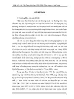
4.3.2.1
Approach-Departure Zone
This zone should be free from obstruction for at least 180
degrees beginning at the base of the ground cushion area
and extending outward and upward on an 8 to 1 slope (8 outward to 1 upward). See Figure 1. For design considerations, a
properly parked helicopter on a multi-helicopter heliport does
not constitute an approach and departure obstruction.
4.3.2.2
Obstruction Free Zone
This zone should include an area outward to one-third RD
greater than diameter OL and also should extend one-third RD
beyond the edge of the approach and departure zone. See Figure 1.
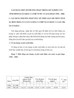
4.3.3
Size
Heliport size should depend on platform configuration
and equipment arrangement, platform orientation, obstruction clearances, the selected helicopters to be utilized, and
prevailing environmental conditions. The heliport ground
cushion area should cover a circle of at least one main rotor
diameter for helicopters operating at maximum gross
weight. See Figure 2. For tandem rotor helicopters, or in
harsh environmental areas (such as the Gulf of Alaska), the
dimensions of the ground cushion area should equal or
exceed the OL of the limiting helicopter. When ground
cushion area is less than one RD (or OL for tandem rotor
helicopters or in harsh environments), the approach and
departure zone should be extended to 360 degrees, and helicopters landing or taking off from such a heliport should be
restricted to less than the certified maximum takeoff weight.
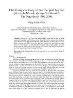
For multi-helicopter heliports, the heliport should be of
sufficient size to allow for the OL of the operating helicopter plus at least one-third the main RD clearance to any portion of a properly parked helicopter with its main rotor
secured (see Figure 3).
4.3.4
Orientation
Orientation of the heliport should be determined by the
platform configuration, equipment arrangement, and prevailing wind.
4.3.5
Access and Egress
The location of access and egress stairways or ladders
should be determined from platform configuration, equipment arrangement, and safety objectives. One primary
access and egress route should be provided. When possible
the access and egress routes should be outside the approach
and departure zone.
RECOMMENDED PRACTICE FOR PLANNING, DESIGNING, AND CONSTRUCTING HELIPORTS FOR FIXED OFFSHORE PLATFORMS
4.3.6
Fire Protection
4.3.7
Heliport fire protection should be considered in the platform fire protection system.
Air Turbulence
Platform configuration and equipment arrangement influence whether the heliport should be elevated. Air turbulence
180°
ARC
APPROACH AND DEPARTURE ZONE
SLOPE OF 8 TO 1
Helideck
RD
Approach / Departure Zone
Approach / Departure Zone
Oil
8 to 1
RD
8 to 1
OL of design
helicopter
intended for use
OBSTRUCTION
RD of design helicopter
intended for use
FREE ZONE
1/3
RD
1/3
3
Obstruction Free Zone
Facilities (Obstruction)
Figure 1—Flight Deck Approach/Departure Zone
4
API RECOMMENDED PRACTICE 2L
spilling over the top of the heliport should be considered
when determining heliport deck clearance.
When a clear airspace of a minimum of 6 feet (1.8
meters) is provided between a heliport elevated above a
building and the building roof, turbulent air can flow under
the heliport and will reduce the effect on helicopter operations. Consideration should be given to an airspace 6 feet
(1.8 meters) or larger.
Safety shelf
R
D
Helideck
RD of largest
helicopter
intended for
use.
0
Figure 2—Recommended Size Heliport
6'-0"
RECOMMENDED PRACTICE FOR PLANNING, DESIGNING, AND CONSTRUCTING HELIPORTS FOR FIXED OFFSHORE PLATFORMS
A safety shelf can also reduce this turbulence problem on
the heliports located on roofs or slab-sided buildings. This
shelf should serve to break the turbulent effect of the wind.
rial or equipment transported by the helicopter should be
considered. Steep stairways or ladders should be avoided.
4.3.10
4.3.8
Heliport Equipment
Lights, refueling hoses, fire extinguishers, tiedown points
and ropes, wind indicators, and access and egress routes
should be located to avoid obstructions in the heliport area.
4.3.9
Material Handling
Access to and egress from the heliport for handling mate-
5
Drainage
The flight deck surface should be provided with adequate
drainage to minimize standing rainwater on the surface.
4.3.11
Maintenance
Heliports which are to accommodate an offshore-based helicopter should be large enough to allow a mechanic performing
routine maintenance to reach all parts of the aircraft safely.
Parked
helicopter
Safety
shelf
R
D
OL
1
m /3
cle ini RD
ar mu
an m
ce
Helicopter
landing or
taking off
Figure 3—Multi-Helicopter Minimum Clearance
6
API RECOMMENDED PRACTICE 2L
4.3.12
Environmental Consideration
In planning a heliport, environmental conditions
expected during the operational life of the heliport should
be considered.
manufacturer’s furnished values given in Table 1. For multiwheeled landing gear, the given value of the contact area is
the sum of the areas for each wheel. The contact area for
float or skid landing gear is that area of the float or skid
around each support strut.
5 Design Procedures For Offshore
Heliports
5.2.4.3
5.1
The load distribution per landing gear in terms of percentage of gross weight is given in Table 1.
GENERAL
The recommended procedures for heliport design are limited to landing sites of steel construction located on fixed
offshore platforms. However, in no way should the design
procedures be construed as a recommendation of steel over
other suitable building materials. Unless otherwise noted,
all related design procedures for fixed offshore platforms
defined in Recommended Practice 2A apply to offshore
heliports. When designing the heliport deck plate for the
design landing load, the large deflection theory (membrane concept) may be used.
5.2
DESIGN LOAD
5.2.1
Dead Weight
The dead weight is the weight of the heliport decking,
stiffeners, supporting structure, and accessories.
5.2.2
Live Load
The live load is uniformly distributed over the entire heliport area including safety shelves when applicable. To allow
for personnel and cargo transfer, rotor down wash, wet snow
or ice, and so forth, a minimum live load of 40 pounds per
square foot (psf), 2 kilo newtons per square meter (2kN/m2)
should be included in the design.
5.2.4.4
Wind Load
Wind load should be determined in accordance with API
Recommended Practice 2A.
5.3
5.2.4.1
Helicopter Landing Load Considerations
General
The flight deck, stiffeners, and supporting structure
should be designed to withstand the helicopter landing load
encountered during exceptionally hard landing after power
failure while hovering. Helicopter parameters are given in
Table 1. It is recommended that helicopter parameters such
as given in Table 1 be obtained from the manufacturer for any
helicopter considered in the heliport design.
5.2.4.2
Contact Area
The maximum contact area per landing gear, used to
design deck plate bending and shear, should conform to the
DESIGN LOAD CONDITIONS
The heliport should be designed for at least the following
combinations of design loads:
a. Dead load plus live load.
b. Dead load plus design landing load. If icing conditions
are prevalent during normal helicopter operations, superposition of an appropriate live load should be considered.
c. Dead load plus live load plus wind load.
5.4
INSTALLATION
Loads experienced during heliport construction including
the static and dynamic forces that occur during lifting, loadout, and transportation should be considered in accordance
with API Recommended Practice 2A.
MATERIAL
All structural materials should conform to API Recommended Practice 2A.
5.6
5.2.4
Design Landing Load
The design landing load is the landing gear load based on
a percent of helicopter’s gross weight times an impact factor
of 1.5. (For percentage and helicopter gross weight, see
Table 1.)
5.5
5.2.3
Load Distribution
FLIGHT DECK SURFACE
The flight deck surface should be nonskid and of solid
construction so that a ground cushion is created by the rotor
downwash. All materials, covering, or coatings used to provide a nonskid surface should be structurally fastened to the
heliport deck or bonded with an adhesive agent that is not
chemically altered in the presence of fuel and oil contamination spills. For helicopters with wheel-type landing gear
operating in harsh environmental areas, the heliport should
be provided with a chocking system such as a grid to secure
the helicopter after landing. The grid size, area, and number
of securing points should be determined with due consideration given to the largest and smallest helicopter the heliport
is designed to accommodate. Grid or rope net-covered flight
decks may not be suitable for certain skid-type landing gear.
Super Puma
Super Puma
Gazelle
ASTAR
Twin Star
Dauphin
332-L
332-C
341-G
350-B/D
355-F
360
360-C
360-C
365-C
365-C
365-N
7,257
7,938
7,938
3,561
3,742
3,742
5,262
1,338
4,309
1,451
1,882
5,080
2,450
2,600
2,799
2,994
2,994
3,401
3,401
3,850
8,351
8,351
1,800
1,950.5
2,305
2,305
2,205
1,656
2,250
7,400
kg
50.0
52.0
52.0
39.8
42.0
42.0
46.0
38.0
48.2
33.3
37.0
48.0
36.1
36.1
37.7
37.7
37.7
37.7
37.7
39.1
51.2
51.2
34.5
35.1
35.1
36.2
36.2
33.5
36.2
49.5
ft
15.2
15.9
15.9
12.1
12.8
12.8
14.0
11.6
14.7
10.2
11.3
14.6
11.0
11.0
11.5
11.5
11.5
11.5
11.5
11.9
15.6
15.6
10.5
10.7
10.7
11.0
11.0
10.2
11.0
15.1
m
Rotor
Diameter
60.2
62.2
62.2
47.5
50.3
50.3
56.1
43.6
57.1
39.2
42.5
57.3
42.9
42.8
44.1
44.1
44.1
44.1
44.1
44.2
61.4
61.4
39.3
42.6
42.6
42.4
42.2
39.8
42.2
59.8
ft
19.0
19.0
19.0
14.5
15.3
15.3
17.1
13.3
17.4
12.0
13.0
17.5
13.1
13.1
13.4
13.4
13.4
13.4
13.4
13.5
18.7
18.7
12.0
13.0
13.0
12.9
12.9
12.1
12.9
18.2
m
Overall
Length
Skid
Skid
Wheel
Wheel
Wheel
Skid
Skid
Skid
Skid
Skid
Skid
Skid
Wheel
Wheel
Wheel
Wheel
Skid
Wheel
Skid
Wheel
Wheel
Wheel
Skid
Skid
Skid
Skid
Wheel
Skid
Wheel
Wheel
Type
2
1
1
1
1
2
2
2
2
2
2
1
2
2
1
1
2
2
2
4
2
2
2
2
2
1
2
1
Fore Aft
Number
49
38
19
19
48
48
27
48
27
27
48
20
14
38
33
33
72
72
46
186
46
in2
319
247
122
123
310
310
174
310
174
174
310
129
46
245
213
213
465
465
297
1,200
297
cm2
Fore
594
cm2
49
90
64
64
48
48
27
48
27
27
48
20
44
66
19
19
114
114
319
581
410
413
310
310
174
310
174
174
310
129
284
426
123
123
735
735
92
594
332 2,142
92
in2
Aft
Contact Area Per
22
22
19
19
32
20
19
29
22
23
22
84
84
84
36
40
33
51
51
34
38
28
Fore
78
78
81
81
68
80
81
71
78
77
78
16
16
16
64
60
67
49
49
66
62
72
Aft
Percentage of
Gross Weight Per
Landing Gear
7.6
15.7
12.2
12.2
7.9
7.9
5.2
7.6
4.5
6.8
7.6
11.6
11.6
11.8
23.7
10.9
10.9
10.9
17.3
14.7
13.3
10.1
ft
2.3
4.8
3.7
3.7
2.4
2.4
1.6
2.3
1.4
2.1
2.3
3.5
3.5
3.6
7.2
3.32
3.32
3.32
5.3
4.5
4.1
3.1
m
Distance Between
Fore and Aft Gears
8.6
8.3
9.3
9.1
9.1
7.8
8.3
7.5
8.7
6.0
7.2
8.3
7.5
8.0
6.5
7.9
7.5
7.9
7.5
6.7
9.8
9.8
6.6
6.9
6.9
7.8
8.5
7.5
8.5
9.8
ft
Table continued on next page.
2.6
2.5
2.8
2.8
2.8
2.4
2.5
2.3
2.7
1.8
2.2
2.5
2.3
2.5
2.0
2.4
2.3
2.4
2.3
2.0
3.0
3.0
2.0
2.1
2.1
2.4
2.6
2.3
2.6
3.0
m
Width Between
Gears
Note: Table 1 does not list all helicopter manufacturers—only those responding to API’s survey. Manufacturers who are not listed above should be consulted with respect to their parameters.
Big Lifter
16,000
Super Transport 17,500
Super Transport 17,000
7,850
8,250
8,250
11,600
2.950
9,500
3,200
4,150
11,200
Bell Helicopter
47G
205A-1
206-B
Jet Ranger
206-L
Lone Ranger
212
Twin
214-B
214-ST
214-ST
222
222-B
222-UT
412
5,402
5,730
6,170
6,610
6,610
7,500
7,500
8,487
18,410
18,410
3,970
4,300
5,071
5,070
4,850
3,650
4,960
16,315
lbs
Gross Weight
Augusta/Atlantic
A-109
Hirando
A-19A
Mark II
Dauphin 2
Alouette II
Alouette III
Puma
Lama
Common
Name
Aerospatiable
315-B
316-B
318-C
319-B
330-J
Manufacture
Model
Helicopter
Table 1—Helicopter Parameters
RECOMMENDED PRACTICE FOR PLANNING, DESIGNING, AND CONSTRUCTING HELIPORTS FOR FIXED OFFSHORE PLATFORMS
7
5,070
5,291
6,283
lbs
1,670
2,050
2,550
3,000
Hughes
269A/B
269C
369HS (Std)
369D
42,000 19,050
42,000 19,050
10,300 4,672
20,000 9,072
3,266
5,897
9,299
3,583
758
930
1,158
1,361
1,406
1,270
1,247
72.3
72.3
44.0
53.7
53.0
56.0
62.0
53.0
25.3
26.8
26.3
26.5
35.4
35.4
35.3
60.0
60.0
50.0
49.0
32.2
32.3
36.1
ft
22.0
22.0
13.4
16.4
16.2
17.1
18.9
16.2
7.7
8.2
8.0
8.
10.8
10.8
10.8
18.3
18.3
5.2
14.9
9.8
9.8
11.0
m
Rotor
Diameter
88.5
88.2
52.5
64.8
62.3
65.8
73.0
62.3
28.9
30.8
30.3
30.5
40.7
40.7
41.5
99.0
99.0
83.1
59.5
38.8
38.9
42.7
ft
27.0
26.9
16.0
19.8
19.0
20.1
22.3
19.0
8.8
9.4
9.2
9.3
12.4
12.4
12.7
30.2
30.2
25.3
18.1
11.8
11.9
13.0
m
Overall
Length
Wheel
Wheel
Wheel
Wheel
Wheel
Wheel
Wheel
Wheel
Skid
Skid
Skid
Skid
Skid
Skid
Skid
Wheel
Wheel
Wheel
Wheel
Skid
Skid
Skid
Type
1
2
1
2
2
2
2
2
4
4
2
2
2
4
2
1
2
1
1
1
2
2
4
2
Fore Aft
Number
154
19
73
994
123
471
258
1,032
1,497
697
194
30
40
160
232
108
71
2,529
1,007
323
1,058
181
206
cm2
11
392
156
50
164
28
32
in2
Fore
181
206
cm2
154
48
73
40
45
43
54
37.5
11
994
310
471
258
290
277
348
242
71
248 1,600
78
503
50
323
82
529
28
32
in2
Aft
Contact Area Per
25
88
5
87
33
41
58
36
34
Fore
75
12
15
13
67
59
42
64
66
Aft
Percentage of
Gross Weight Per
Landing Gear
24.4
27.0
16.4
28.9
10.4
28.3
23.5
17.8
25.8
22.5
24.8
15.3
ft
7.4
8.2
5.0
8.8
3.2
8.6
7.2
5.4
7.9
6.9
7.6
4.7
m
Distance Between
Fore and Aft Gears
19.8
13.0
8.0
9.0
11.0
12.0
14.0
12.2
6.5
6.5
6.8
6.8
7.5
7.5
7.2
11.2
11.2
12.9
8.8
8.5
8.3
8.2
ft
6.0
4.0
2.4
2.7
3.4
3.7
4.3
3.7
2.0
2.0
2.1
2.1
2.3
2.3
2.2
3.4
3.4
3.9
2.7
2.6
2.5
2.5
m
Width Between
Gears
Note: Table 1 does not list all helicopter manufacturers—only those responding to API’s survey. Manufacturers who are not listed above should be consulted with respect to their parameters.
S-64
S-65C
S-76
S-78-C
Skycrane
3,100
2,800
Hiller
UH-12-L-4
UH-12E/E-4
7,200
13,000
20,500
7,900
2,750
Fairchild
FH-1100
Sikorsky
S-55T
S-58T
S-61N L
S-62
2,300
2,400
2,850
kg
Gross Weight
48,500 21,900
50,000 22,680
22,000 10,030
18,700 8,482
Hughes 300
Hughes 300C
Hughes 500C
Hughes 500D/E
Twin Jet II
Space Ship
Boeing Vertol
BO-105C
B0-105CBS
BK-117
234
CH-47-234
107-II
179
Common
Name
Manufacture
Model
Helicopter
Table 1—Helicopter Parameters (Cont.)
8
API RECOMMENDED PRACTICE 2L
RECOMMENDED PRACTICE FOR PLANNING, DESIGNING, AND CONSTRUCTING HELIPORTS FOR FIXED OFFSHORE PLATFORMS
5.7
ACCESS AND EGRESS ROUTE
The heliport should be provided with a primary access
and egress route. Where practical, the primary route should
be provided with a depressed waiting area minimum of 7
feet (2.0 meters) below the elevation of the flight deck surface. Where a secondary route is provided, it should be limited to
emergency use only, where normal passenger flow is prohibited.
5.8
SAFETY NET AND SHELF
The heliport should provide a safety net or shelf for protection of personnel at least 5 feet (1.5 meters) wide (measured horizontally) around the perimeter, except that at
stairwells the safety net or shelf should extend completely
around the opening. The safety net or shelf need not extend
around stairways oriented perpendicular to the heliport
perimeter. The safety net or shelf should produce an outward and upward inclined surface beginning at a slight drop
in elevation below the flight deck. The outer edge should not
protrude above the flight deck. Such safety nets or shelves
should be designed to support a minimum concentrated load
of 200 pounds (100 kilograms) at any point. The safety shelf
should also be designed in accordance with 5.3, Items a and c.
5.9
TIEDOWN POINTS
A minimum of four tiedown points should be provided
for securing each helicopter to the flight deck. These
tiedown points should be recessed where practical. If not
recessed, the tiedowns constitute a landing gear hazard and
require obstruction markings. The tiedown points should be
arranged so as to secure one helicopter in the middle of the
heliport. On multi-helicopter heliports sufficient tiedown
points should be provided for each helicopter parking area.
The tiedown points should be so located and of such
strength and construction as to be suitable for securing the
largest helicopter the heliport is designed to accommodate
during the maximum anticipated environmental condition.
5.10
LIGHTING
For night use, perimeter lights should be used to delineate
the heliport flight deck. Alternating yellow and blue omnidirectional lights of approximately 30–60 watts should be
spaced at intervals to adequately outline the flight deck. A
minimum of eight lights are recommended for each heliport.
Adequate shielding should be used on any floodlighting that
could dazzle the pilot during an approach for landing.
Obstructions that are not obvious should be marked with
omnidirectional red lights of at least 30 watts. Where the
highest point on the platform exceeds the elevation of the
flight deck by more than 50 feet (15 meters), an omnidirectional red light should be fitted at that point, with additional
such lights fitted at 35 feet (10 meters) intervals down to the
elevation of the flight deck. An emergency power supply
9
should provide power to the perimeter and obstruction lighting and to lighting along the heliport access and egress
routes. Flight deck lights should be outboard of the flight
deck and should not extend over 6 inches (15 centimeters)
above the deck surface. They should be guarded, have no
exposed wiring, and be located so as not to be an obstruction. Any inboard lighting should be flush mounted.
5.11
5.11.1
HELIPORT MARKINGS
General
A minimum aiming circle 20 feet (6 meters) outside
diameter and 16 inches (40 centimeters) wide should mark
the center of the available flight deck, not necessarily the
center of the heliport. A 16 inch (40 centimeter) wide stripe
should be used to mark the boundary of the heliport flight
deck. Any contrasting color can be used; however, red is
reserved for obstruction markings. In addition to the aiming
circle and marking provided for normal helicopter operations, a company logo, or the internationally recognized
marking for a helicopter flight deck may be provided. The
internationally recognized marking consists of the letter H
[10 feet high x 51/2 feet wide (3 meters x 1.7 meters)]
painted white and centered in the middle of the aiming circle. The width of the legs of the H should be 16 inches (40
centimeters). If a color other than white is used, the letter
coloring should contrast with the deck coloring but should
not be red. The flight deck may also be marked with the operator's name, area, and block number. A walkway may be
marked from the aiming circle to the primary access and egress
route. See Figure 4. The secondary (emergency) exit should be
prominently marked for pilot identification. See Figure 4.
5.11.2
Limitation Markings
Since an offshore heliport is limited to helicopters of or
under a certain gross weight or size the heliport should be
marked to indicate these limitations. The recommended
method of designating the heliport limitation is to indicate
the allowable weight to the nearest thousand pounds. Below
this allowable weight designation, the flight deck dimension
is shown to the nearest foot.
Square, octagonal, hexagonal, pentagonal, or circular
flight deck dimensions should be indicated by a single number. Dimensions of rectangular flight decks should be indicated by the width times the length. These dimensions
should not include the solid safety shelf or safety fence.
Metric equivalents should not be used for this purpose. It
is recommended these limitations be marked by red numerals on a white background, located to the right and above
the heliport symbol. They should be visible from the principal direction of approach. The square and numeral should
be of such size as to be readily discernible by the pilot of the
approaching helicopter in sufficient time to effect a goaround if necessary. See Figure 4.
10
API RECOMMENDED PRACTICE 2L
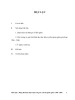
5.11.3 Obstruction Marking
Marking should be placed on the heliport flight deck to
alert the pilot of obstructions and guide him to select a safe
landing area on the heliport. All obstruction markings should
be painted a contrasting color, preferably red. A main rotor
blade obstruction should be denoted by a 6 inch (15 centimeter) wide arc measured from the obstruction to a point on the
flight deck, outside of which the pilot can set the helicopter
landing gear and maintain proper main rotor blade clearance
one-third RD. This distance is one-third the rotor diameter
plus one-half the overall length minus one-half the width
between the gears (1/3 RD + 1/2 OL – 1/2 GW). As a guideline,
40 feet (10.9 meters) provides suitable clearance for a large
helicopter and 26 feet (8 meters) for a small helicopter. See
Figure 5. This marking does not necessarily ensure tail rotor
blade clearance. Tail rotor blade obstructions should be
painted in a contrasting color, preferably red or international
orange. If the obstruction is slender and hard to see, it may
also be hash marked, A 3 feet (1 meter) wide rectangle, a mini-
;;
;;
;;
;;
;;
;;
;;
;;
;;
;;
;;
;;
;;
;;
;;
;;
;;
;;
;;
;;
;;
;;;;;;;;;;
Primary route
19
50
5'-6"
(1.7 m)
10'-0"
(3 m)
16"
(40 cm)
16"
(40 cm)
(4 16
0 "
cm
)
16"
(40 cm)
20'-0" dia.
(6 m)
OPERATOR
AREA – BLOCK – DESIGNATION
Safety net shown
Figure 4—Heliport Marking Scheme
Secondary
route
RECOMMENDED PRACTICE FOR PLANNING, DESIGNING, AND CONSTRUCTING HELIPORTS FOR FIXED OFFSHORE PLATFORMS
mum of 3 feet (1 meter) in length, of 6 inches (15 centimeters)
wide alternating red and yellow diagonal stripes should be
made on the flight deck to denote tail rotor obstructions. See
Figure 6.
A 3 feet (1 meter) wide marking should be made around
all stairways. This area should be painted with alternating
red and yellow 6 inch (15 centimeter) wide diagonal stripes
if it is a physical tail rotor obstruction and solid red if there
is no physical obstruction. See Figure 6.
Landing gear obstructions should be denoted by painting
the area around the obstruction with a contrasting color. For
obstructions such as non-recessed tiedown points located
in the touchdown area, a circular marking 2 feet (0.6
meter) in diameter should denote the landing gear obstruc-
"R
1 /3
;;
;;
;;
;;
;;
;;
;;
;;
;;
;;
;;
;;
;;
;;
;;
;;
;;
;;
;;
;;
;;
;;;;;;;;;;
D
Main rotor
obstruction
(15
6"
cm
)
Red
Oil
rall
Ove
11
19
50
th
leng
OPERATOR
AREA – BLOCK – DESIGNATION
Figure 5—Marking for Main Rotor Blade Obstruction
12
API RECOMMENDED PRACTICE 2L
tions. See Figure 7. In general, conflicts between obstruction markings and other visual aids should be avoided. If a
conflict does exist, the obstruction markings color should
control.
5.11.4
Closed Heliport
When a heliport is “closed,” a large white or contrasting
“X” should be made on the flight deck. It should be large
enough to ensure pilot recognition a sufficient distance to
effect a go-around. This marking should be used for permanently closed heliports, or when they are temporarily closed
for hazardous conditions, and so forth.
5.12
DRAWINGS, SPECIFICATIONS AND
CONSTRUCTION
The heliport drawings and specifications as well as the
fabrication, installation, inspection, and surveys, should
conform to API Recommended Practice 2A.
6
6.1
Safety Considerations
FUELING STATIONS
Helicopter fueling stations (hose reels) should be located
to avoid obstructing any access or egress route serving the
helicopter flight deck.
3'
(1 m)
Red
(no physical obstruction)
Solid
safety
shelf
3'
(1 m)
With physical
tail rotor
obstruction
Tail rotor
obstruction
3'
(1 m)
min.
3'
(1 m)
6" (15 cm)
yellow and red
stripes
Figure 6—Marking for Tail Rotor Blade Obstruction
19
50