Bsi bs au 040 4a 1966 (2000)
Bạn đang xem bản rút gọn của tài liệu. Xem và tải ngay bản đầy đủ của tài liệu tại đây (732.12 KB, 18 trang )
BRITISH STANDARD AUTOMOBILE SERIES
BS AU
40-4a:1 966
Incorp orating
C O NFI RME D
APRI L 1 987
Specification for
Motor vehicle lighting
and signalling
equipment —
Part 4a: Sealed beam headlamps
UD C 62 9 . 1 1 3 . 0 1 8: 65 4. 9 1 2 . 8: 62 9 . 1 1 3 . 0 6: 62 8. 9
Reprodu ced by I H S u n d er l i cen se wi th BSI - U n con trol l ed Copy
Am endm ent No.
1
BS AU 40-4a:1 966
Co-operating organizations
The Illumination Industry Standards Committee under whose supervision this
British Standard was prepared, consists of representatives from the following
Government departments and scientific and industrial organizations:
Association of Public Lighting Engineers*
British Electrical and Allied Manufacturers’ Association
British Glass Industry Research Association
British Railways Board*
Electric Lamp Industry Council*
Electric Light Fittings Association*
Electricity Council, the Generating Board and the Area Boards in England and Wales*
Gas Council
Glass Manufacturers’ Federation
Illuminating Engineering Society*
Independent Lamp Manufacturers’ Export Group*
Institution of Electrical Engineers*
Institution of Gas Engineers
Institution of Municipal Engineers
London Transport Board*
Medical Research Council
Ministry of Aviation*
Ministry of Defence, Navy Department*
Ministry of Housing and Local Government
Ministry of Labour (H.M. Factory Inspectorate)
Ministry of Public Building & Works*
Ministry of Technology — Building Research Station
Ministry of Transport*
National Physical Laboratory (Ministry of Technology)*
Post Office*
Royal Institute of British Architects
Society of British Gas Industries
Society of Glass Technology*
The Government departments and scientific and industrial organizations
marked with an asterisk in the above list, together with the following, were
directly represented on the committee entrusted with the preparation of
this standard.
British Cycle & Motor Cycle Industries Association Ltd.
Electrical Contractors Association (Incorporated)
Greater London Council
Municipal Passenger Transport Association (Incorporated)
Public Transport Association (Incorporated)
Society of Motor Manufacturers & Traders Ltd.
This British Standard, having
been approved by the
Illumination Industry
Standards Committee and
endorsed by the Chairman of
the Engineering Divisional
Council, was published
under the authority of the
General Council on
27 April 1966
© BSI 02-2000
The following BSI references
relate to the work on this
standard:
Committee references LGE/6,
LGG/6/3
Draft for comment D64/1958
ISBN 0 5 80 345 5 3 X
Reprodu ced by I H S u n d er l i cen se wi th BSI - U n con trol l ed Copy
Amendments issued since publication
Amd. No.
2188
Date of issue
December
1976
Comments
Indicated by a sideline in the margin
BS AU 40-4a:1 966
Contents
Page
Co- operating organizations
Inside front cover
Foreword
ii
Section 1 . General
1
Scope
1
2
Definitions
1
3
Marking
1
Section 2. Tests
4
Sampling and testing procedure
2
5
Dimensions
2
6
Thermal shock
2
7
Current limits
2
8
Photometric requirements and test
2
9
Visual aim
2
10
Life
2
11
Conditions of compliance
10
Figure 1 — 7 in diameter sealed beam headlamp unit
11
Figure 2 — 5
12
# in diameter sealed beam headlamp unit Type 1
Figure 3 — 5 # in diameter sealed beam headlamp unit Type 2
Table 1 — 7 inch 1 2 volt 60/45 watt right hand drive unit (Dip left)
Table 2 — 5
Table 3 — 5
# inch 1 2 volt 37" watt Type 1
# inch 1 2 volt 37" /50 W Type 2 right hand drive unit (Dip left)
Table 4 — 7 inch 1 2 volt 75/50 watt right hand drive unit (Dip left)
© BSI 02- 2000
13
3
4
5
6
Table 5 — 7 inch 1 2 volt 60/50 watt right hand drive unit (Dip left)
7
Table 6 — 5
8
# inch 1 2 volt 37" /60 watt right hand drive unit (Type 2)
Table 7 — 5 # inch, 1 2 volt, 75 watt (Type 1 )
Reprodu ced by I H S u n d er l i cen se wi th BSI - U n con trol l ed Copy
3
Appendix A Statistical basis
9
i
BS AU 40-4a:1 966
Foreword
This British Standard has been prepared under the authority of the Illumination
Industry Standards Committee after consultation with the Automobile Industry
Standards Committee, and it is based upon data- sheets SMMT 74: 1 960 and
SMMT 77: 1 962 of the Society of Motor Manufacturers and Traders Ltd.
This standard forms Part 4 of BS AU 40; other parts are:
—
Part 1: Side, rear, parking and stop lamps, and direction indicators;
—
Part 2: Reflex reflectors for vehicles, including cycles;
Part 3: Headlamps with prefocused filament lamps (in course of
preparation);
—
—
Part 5: Rotating beacons (in course of preparation).
It will be seen that compliance with this specification is checked by the testing of
samples from batches of units. The statistical basis for the sampling system is
explained in Appendix A to the standard.
All materials and components used in the construction of these units are required
to comply with relevant British Standards.
A British Standard does not purport to include all the necessary provisions of a
contract. Users of British Standards are responsible for their correct application.
Compliance with a British Standard does not of itself confer immunity
from legal obligations.
Summary of pages
This document comprises a front cover, an inside front cover, pages i and ii,
pages 1 to 1 3 and a back cover.
This standard has been updated (see copyright date) and may have had
amendments incorporated. This will be indicated in the amendment table on the
inside front cover.
ii
Reprodu ced by I H S u n d er l i cen se wi th BSI - U n con trol l ed Copy
© BSI 02- 2000
BS AU 40-4a:1 966
Section 1 . General
2.6
7-inch two-headlamp system
1 Scope
two similar 7 inch sealed beam units used together
This standard specifies requirements for 1 2 volt
on a vehicle
sealed beam headlamp units for use on vehicles, and
2.7
tests for photometric properties, visual aim, current,
four-headlamp system
life and resistance to thermal shock.
NOTE
In general, the inch dimensions given in this
specification are the standard.
Where dimensions are given in both systems, the first figure is
four units used together on a vehicle and lit to
provide the main beam, two units only being lit to
provide the dipped beam
the standard and the second is an approximate conversion. For
NOTE
Two systems are employed at present. The first uses
accurate conversions reference should be made to BS 350,
four 5
inch units, two being Type 1 and two Type 2 and the
“
Conversion factors and tables”.
#
second system is a mixed one using two 7 inch units and
two 5
#
2 Definitions
2.8
For the purposes of this specification the following
batch
inch (Type 1 ) units.
definitions apply:
all the lamps of one type put forward at one time for
2.1
acceptance
mechanically aimable sealed beam units
a sealed unit having three pads on the face of the
3 Marking
lens, pre- aimed during manufacture to form an
The lamp shall be legibly and durably marked with
aiming plane
the following information:
NOTE
The unit is pre- aimed during manufacture to form an
aiming plane normal to the vehicle axis when the beam is
correctly aimed.
2.2
main (driving or upper) beam
a beam of light intended primarily for distant
a) Nominal voltage.
b) Nominal wattage.
c) Trade mark.
d) Where appropriate, a mark indicating the
rule- of- the- road.
illumination of the road, when no other vehicle is
e) With the number of this British Standard,
approaching
i. e. BS AU 40.
2.3
dipped (meeting or lower) beam
a beam of light intended for illumination of the road
ahead of the vehicle when meeting other road users
2.4
7-inch sealed beam unit
a unit 7 inches in diameter having two filaments,
one providing a main beam and the other a dipped
beam
2.5
# -inch sealed beam unit
a unit 5 # inches in diameter. Type 1 has a single
5
NOTE
The mark BS AU 40 on or in relation to the product is a
claim by the manufacturer that it complies with the
requirements of the standard.
The British Standards Institution is the owner of a registered
certification trade mark. This is shown below, enclosed in the
words “Approved to British Standard”. This mark can be used
only by manufacturers licensed under the certification mark
scheme operated by the BSI. The presence of this mark on or in
relation to a product is an assurance that the goods have been
produced to comply with the requirements of the
British Standard under a system of supervision, control and
testing operated during manufacture and including periodical
inspection at the manufacturer’s works in accordance with the
certification mark scheme of the BSI.
Further particulars of the terms of licence may be obtained
from the Director, British Standards Institution, 2, Park Street,
London, W. 1 .
filament which contributes to the main beam and
Type 2 has two filaments, one of which contributes
to the main beam and the other provides the dipped
beam
© BSI 02- 2000
Reprodu ced by I H S u n d er l i cen se wi th BSI - U n con trol l ed Copy
1
BS AU 40-4a:1 966
Section 2. Tests
8 Photometric requirements and test
4 Sampling and testing procedure
Following the ageing prescribed in Clause 7
the photometric test voltage (given in the
The units for testing shall be selected so as to ensure
appropriate table) shall then be applied to the
proper representation of the batch, as follows:
terminals of the unit.
a)
The units shall be mounted in such a way that the
Metho d of sam p ling.
i)
A b atch of
A.
1 000
units or less .
photo- cell and centre of the unit. This specifies
A b atch p acked in 1 0 o r less
containers .
Units shall be selected from
detailed above, when measured at 60 ft (1 8. 3 m)
A b atch p acked in m ore than 1 0
containers .
Units shall be selected from at
least one half of the total number of
containers, with a minimum of 1 0.
ii)
A b atch of m ore than
1 000
units.
Lamps shall be selected as far as possible from
b)
the H—V point (see Note 2 below) .
The light intensities from a unit mounted as
each container.
B.
aiming plane is perpendicular to a line through the
from the unit face shall comply with the values
given in the appropriate table.
! ° is permissible for any test point.
NOTE 1
A tolerance of ±
NOTE 2
In locating the test points, the line formed by the
intersection of a vertical plane through the lamp axis with the
test screen is designated as V. The line formed by the intersection
of a horizontal plane through the unit centre and the test screen
one third of the number of containers, with a
is designated as H. The point at the intersection of these two lines
maximum of 1 0.
is designated as H—V. The other points on the screen are
designated by similar symbols to indicate the number of degrees
Tests.
i)
For single filam ent units .
of arc above or below H and the number of degrees of arc to the
left or right of V for an observer facing the screen, for
example, 4D—3L is a point 4 degrees below H and 3 degrees to
1 5 shall be selected from the batch, 1 0 units
the left of V, and 1 U—V is a point 1 degree above H in the median
shall be tested in accordance with
vertical plane.
Clauses, 3 , 5 , 7 and 1 0 . The remaining 5 units
shall be tested in accordance with
Clauses 6 , 8 , and 9 .
ii)
For doub le filam ent units.
25 shall be selected from the batch, 1 0 of these
shall be tested in accordance with Clauses 3 , 5
and 7 . 20 of these, including the 1 0 referred to
above, shall be tested in accordance with
Clause 1 0 , 1 0 being tested on the main beam
filament and 1 0 on the dipped beam filament.
The remaining 5 units shall be tested in
accordance with Clauses 6 , 8 and 9 .
9 Visual aim
When the unit is mounted as in Clause 8 , it shall be
possible for the high intensity zone of the main
beam of 7 inch and 5
# inch Type 1 units to be set by
three experienced observers to within maximum
vertical and horizontal deviations of ± 0. 2
and ± 0. 4 degrees respectively at a distance
of 25 ft (7. 6 m).
1 0 Life
When mounted in the position of normal use the
units shall be tested on an a. c. supply at the life test
5 Dimensions
The units shall comply with the dimensions given
in Figure 1 , Figure 2 or Figure 3 as appropriate.
voltage given in the appropriate table, at a nominal
frequency of 50 c/s.
The momentary fluctuations of the test voltage
during the test shall not exceed ± 1 per cent and
6 Thermal shock
The higher- wattage filament shall be operated for
five minutes in the normal- operating position of the
unit at 1 4 volts. The unit shall then be quickly
immersed, lens first, in water at 1 5 ° C until cool.
there shall be no sensible departure of the average
value throughout the test from the specified value.
Lamps shall be switched off twice daily for periods
of not less than 1 5 minutes, such periods not being
considered as part of the life of the lamp.
After this test there shall be neither evidence of
Lamps which are accidentally broken before the
moisture in the unit nor sign of failure in the glass.
completion of the test shall, when necessary, be
7 Current limits
lamps complete the test. Any such broken lamps
replaced to ensure that the required number of
The units shall be aged at the life- test voltage
shall be neglected in calculating the results.
given in Table 1 to Table 7 as appropriate for at
The test shall be considered to have terminated
least 30 minutes. The current passed shall then be
when the requirements of the tables have been
measured with the specified voltage applied to the
satisfied.
terminals of the unit.
2
Reprodu ced by I H S u n d er l i cen se wi th BSI - U n con trol l ed Copy
© BSI 02- 2000
BS AU 40-4a:1 966
1 1 Conditions of compliance
A batch shall be considered as complying with this
specification if the requirements contained in a)
to e) inclusive below are satisfied. If the batch fails
to satisfy the requirements of any of these clauses,
it shall be deemed not to comply with the
specification.
a) Not more than 1 unit of the sample tested shall
fail any one of the requirements described in
Clauses 3 and 5 .
b) Not more than two units of the sample tested
shall fail any one of the tests described in
Clauses 8 and 9.
NOTE Clause 9 is applicable only to 7-inch and 5# -inch
Type 1 units.
c) The average of the currents passed by the unit
in the sample tested under Clause 7 shall lie
within the appropriate limits shown in the
appropriate tables.
d) No unit shall fail the test prescribed in
Clause 6 .
e) The average life of the sample selected for the
test shall not fall below the minimum average
value specified in the appropriate tables.
f) The number of units in the sample having lives
shorter than 60 per cent of the specified
minimum average shall not exceed the value
given in the appropriate table.
Table 1 — 7 inch 1 2 volt 60/45 watt right hand drive unit (Dip left)
1 A. Photometric requirements at 1 2.8 V on the unit terminals
Main beam
Position
2U—3R & 3L
1U—3R & 3L
" D—V
Dipped beam
Cd Max.
Cd Min.
" D—3R & 3L
" D—6R & 6L
" D—9R & 9L
" D—12R & 12L
2D—V
2D—9R & 9L
3D—V
3D—12R—12L
4D—V
5 000
Position
Cd Max.
1 250
5 000
36 000
1 " U—1L to L
1U—1R to R
" U—1L to 3L
12 000
5 000
3 000
" U—1R to R
800
" D—1L to L 10 000
" D—2L
" D—1R to R 2 000
1D—1R to 6R
1 " D—2L
1 " D—9L
1 " D—9R
12 500
4D—4L
125
10U—90Ua
1 500
5 000
2 000
2 500
1 000
a From the normally exposed surface of the lens
1 000
500
2 000
Cd Min.
3 750
750
10 000
1 500
750
1 B. Current limits at 1 2.8 V on the unit terminals
Average current limits for 1 0 units
Minimum
Main filament:
Dipped filament:
Maximum
4.41 amp
3.31 amp
4.97 amp
3.73 amp
1 C. Life test at 1 4.0 V on the unit terminals
Maximum number of
Minimum
average life of
10 units
Main filament:
Dipped filament:
© BSI 02-2000
Reprodu ced by I H S u n d er l i cen se wi th BSI - U n con trol l ed Copy
138 h
221 h
units failing
Design life
200 h
320 h
before 60 per cent of
2
2
design life
3
BS AU 40-4a:1 966
Table 2 — 5
# inch 1 2 volt 37" watt Type 1
2A. Photometric requirements at 1 2.8 V on the unit terminals
Main beam
Position
3U—3L & 3R
2U—3L & 3R
1U—3L & 3R
Cd Max.
" D—V
" D—3L & 3R
" D—6L & 6R
" D—9L & 9R
Cd Min.
Position
450
750
3 000
" D—12L & 12R
2D—V
2D—9L & 9R
25 000
12 000
6 000
2 000
3D—V
3D—12D & 12R
4D—V
Cd Max.
2 500
Cd Min.
750
3 000
1 250
1 500
600
2B. Current limits at 1 2.8 V on the unit terminals
Average current limits for 1 0 units
Minimum
2.75 amp
Maximum
3.11 amp
2C. Life test at 1 4.0 V on the unit terminals (Main Beam)
Maximum number of units failing
Minimum average
life of
138 h
4
10 units
Design life
200 h
Reprodu ced by I H S u n d er l i cen se wi th BSI - U n con trol l ed Copy
before 60 per cent of design life
2
© BSI 02-2000
BS AU 40-4a:1 966
Table 3 — 5
# inch 1 2 volt 37" /50 W Type 2 right hand
drive unit (Dip left)
3A. Photometric requirements at 1 2.8 V on the unit terminals
Main beam
Position
Dipped beam
Cd Max.
3U—3L & 3R
2U—3L & 3R
1U—3L & 3R
" D—V
" D—3L & 3R
" D—6L & 6R
" D—9L & 9R
" D—12L & 12R
2D—V
2D—9L & 9R
3D—V
3D—12L & 12R
4D—V
Cd Min.
Position
300
750
2 000
1U—1R to R
" U—1R to R
" D—1R to R
7 000
3 000
2 000
1 " U—1L to L 1 000
" U—1L to 3L 2 000
1 000
750
2 000
" D—2L
1D—6R
1 " D—2L
1 " D—9L
1 " D—9R
4D—4L
10U to 90Ua
750
1 000
400
2 500
Cd Max.
650
850
2 000
10 000
12 500
125
Cd Min.
3 750
750
12 000
1 500
750
a From the normally exposed surface of the lens
3B. Current limits at 1 2.8 V on the unit terminals
Average current limits for 1 0 units
Minimum
Main filament
Dipped filament
2.75 amp
3.68 amp
Maximum
3.11 amp
4.14 amp
3C. Life test at 1 4.0 V on the unit terminals
Minimum
Design
failing before 60 per cent
of
life
of design life
10 units
Main filament 138 h
Dipped filament 221 h
© BSI 02-2000
Reprodu ced by I H S u n d er l i cen se wi th BSI - U n con trol l ed Copy
Maximum number of units
average life
200 h 2
320 h 2
5
BS AU 40-4a:1 966
Table 4 — 7 inch 1 2 volt 75/50 watt right hand drive unit (Dip left)
4A. Photometric requirements at 1 2.8 V on the unit terminals
Main beam
Position
2U—3R & 3L
1U—3R & 3L
" D—V
Cd Max.
" D—3R
" D—3L
" D—6L & 6R
" D—9R & 9L
" D—12R & 12L
2D—V
2D—9R & 9L
3D—V
3D—12R & 12L
4D—V
6 000
Dipped beam
Cd Min.
Position
Cd Max.
1 750
7 000
40 000
1 " U—1L to L
1U—1R to R
" U—1L to 3L
1 000
500
2 000
20 000
16 000
6 500
" U—1R to R
" D—1L to L
800
10 000
4 000
2 000
6 000
" D—2L
" D—1R to R
1D—1R to 6R
1 " D—2L
1 " D—9L
1 " D—9R
4D—4L
10U—90Ua
3 000
3 000
1 250
a From the normally exposed surface of the lens
2 000
12 500
125
Cd Min.
4 200
800
11 000
1 700
800
4B. Current limits at 1 2.8 V on the unit terminals
Average current limits for 1 0 units
Minimum
Main filament
Dipped filament
Maximum
5.51 amp
3.68 amp
6.22 amp
4.14 amp
4C. Life test at 1 4.0 V on the unit terminals
Minimum
Main filament
Dipped filament
6
Maximum number
average
Design
of units failing
life of
life
before 60 per cent of
10 units
105 h
221 h
Reprodu ced by I H S u n d er l i cen se wi th BSI - U n con trol l ed Copy
150 h
320 h
2
2
design life
© BSI 02-2000
BS AU 40-4a:1 966
Table 5 — 7 inch 1 2 volt 60/50 watt right hand drive unit (Dip left)
5A. Photometric requirements at 1 2.8 V on the unit terminals
Main beam
Position
Dipped beam
Cd Max.
2U—V
1U—3L & 3R
H—V
Cd Min.
1 000
2 000
20 000
10 000
3 250
1 500
750
H—3L & 3R
H—6L & 6R
H—9L & 9R
H—12L & 12R
1 " D—V
1 " D—9L & 9R
2 " D—V
2 " D—12L & 12R
4D—V
5 000
1 500
2 500
750
5 000
Position
Cd Max.
10U to 90Ua
1U—1 " R to R
" U—1 " R to R
" D—1 " R to R
1 " U—1L to L
125
700
1 000
2 500
1 400
" U—1L to 3L
" D—1 " L
1D—6R
1 " D—2L
2 700
20 000
1 " D—9R & 9L
2D—15R & 15L
4D—4L
12 500
Cd Min.
8 000
750
15 000
750
700
a From the normally exposed surface of the lens
5B. Current limits at 1 2.8 V on the unit terminals
Average current limits for 1 0 units
Minimum
Main filament
Dipped filament
4.41 amp
3.68 amp
Maximum
4.97 amp
4.14 amp
5C. Life test at 1 4.0 V on the unit terminals
Minimum
Main filament
Dipped filament
© BSI 02-2000
Reprodu ced by I H S u n d er l i cen se wi th BSI - U n con trol l ed Copy
Maximum number of units
average life
Design
failing before 60 per cent of
of
life
design life
10 units
138 h
221 h
200 h 2
320 h 2
7
BS AU 40-4a:1 966
Table 6 — 5
# inch 1 2 volt 37 " /60 watt right hand
drive unit (Type 2)
6A. Photometric requirements at 1 2.8 V on the unit terminals
Main beam
Position
3U—3L & 3R
2U—3L & 3R
1U—3L & 3R
Cd Max.
Dipped beam
Cd Min.
Position
Cd Max.
300
750
2 000
1U—1R to R
" U—1R to R
" D—1R to R
650
850
2 000
" D—V
" D—3L & 3R
" D—6L & 6R
" D—9L & 9R
" D—12L & 12R
2D—V
2D—9L & 9R
7 000
3 000
2 000
1 " U—1L to L
" U—1L to 3L
1 000
2 000
1 000
750
2 000
3D—V
3D—12L & 12R
4D—V
1 000
400
" D—2L
1D—6R
1 " D—2L
1 " D—9L
1 " D—9R
4D—4L
10U to 90Ua
750
2 500
15 000
Cd Min.
6 000
750
15 000
1 500
750
12 500
125
a From the normally exposed surface of the lens
6B. Current limits at 1 2.8 V on the unit terminals
Average current limits for 1 0 units
Minimum
Main filament
Dipped filament
Maximum
2.75 amp
4.41 amp
3.11 amp
4.97 amp
6C. Life test at 1 4.0 V on the unit terminals
Minimum
Design
failing before 60 per cent of
of
life
design life
10 units
Main filament
138 h
Dipped filament 221 h
8
Maximum number of units
average life
Reprodu ced by I H S u n d er l i cen se wi th BSI - U n con trol l ed Copy
200 h 2
320 h 2
© BSI 02-2000
BS AU 40-4a:1 966
Table 7 — 5
# inch, 1 2 volt, 75 watt (Type 1 )
7A. Photometric requirements at 1 2.8 V on the unit terminals
Main beam
Position
Cd Max.
Cd Min.
2U—3R
2U—3L
1U—3R
Position
" D—9L
" D—12R
" D—12L
1 250
1 250
7 500
1U—3L
D—V
D—3R
"
"
" D—3L
" D—6R
" D—6L
" D—9R
Cd Max.
Cd Min.
2 000
750
750
7 500
65 000
28 000
2D—V
2D—12R
2D—12L
7 500
500
500
28 000
7 000
7 000
3D—V
3D—12R
3D—12L
2 500
200
200
2 000
4D—V
6 500
* From the normally exposed surface of the lens
7B. Current limits at 1 2.8 V on the unit terminals
Average current limits for 1 0 units
Minimum
Main filament
5.50 amp
Maximum
6.20 amp
7C. Life test at 1 4.0 V on the unit terminals
Minimum
Design
failing before 60 per cent of
of
life
design life
10 units
Main filament
© BSI 02-2000
Reprodu ced by I H S u n d er l i cen se wi th BSI - U n con trol l ed Copy
Maximum number of units
average life
35 h
50 h
2
9
BS AU 40-4a:1 966
Appendix A Statistical basis
2) 98 per cent of the lamps satisfy each single
It is impracticable and uneconomic to test every
3) 90 per cent of the lamps satisfy each single
lamp in a batch but, by the use of statistical
requirement (Clauses 8 and 9 ) .
requirement (Clauses 3 and 5 ) .
sampling theory, it is possible to design tests on
small samples which will determine whether the
quality of a batch is acceptable.
Accordingly, test quantities, quality limits and
compliance numbers have been so specified that if
the whole of a batch had been tested and found to
comply with each of the following quality
statements, there would be a 0. 975 (39/40)
probability that such a batch, if tested (by sampling)
in accordance with the specification, would be found
to comply with the standard. The quality
statements are:
1 ) 99 per cent of the lamps satisfy each single
requirement (Clause 6 ).
10
Reprodu ced by I H S u n d er l i cen se wi th BSI - U n con trol l ed Copy
4) The average values satisfy the requirements
for initial current (Clause 7 ).
A batch of lamps complies with this standard if,
when a sample is tested according to the standard,
in all the test quantities, the numbers of lamps
outside the specified quality limits (such lamps are
not necessarily failures or faulty lamps) are not
greater than the related compliance numbers, and
the average life is not less than the related
minimum average life. Individual lamps are deemed
to comply with the requirements of the standard if
they belong to, and comply consequently upon
belonging to, a batch which complies with the
standard.
© BSI 02- 2000
© BSI 02 - 2 000
11
Reprodu ced by I H S u n d er l i cen se wi th BSI - U n con trol l ed Copy
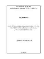
Figure 1 — 7 in diameter sealed beam headlamp unit
BS AU 40-4a:1 966
12
© BSI 02 - 2 000
Reprodu ced by I H S u n d er l i cen se wi th BSI - U n con trol l ed Copy
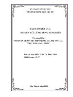
Figure 2 — 5
#
in diameter sealed beam headlamp unit Type 1
BS AU 40-4a:1 966
© BSI 02 - 2 000
13
Reprodu ced by I H S u n d er l i cen se wi th BSI - U n con trol l ed Copy
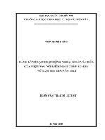
Figure 3 — 5
#
in diameter sealed beam headlamp unit Type 2
BS AU 40-4a:1 966
BS AU
40-4a:1 966
BSI — British Standards Institution
BS I is the indep endent national b ody res p ons ib le for p rep aring
Britis h S tandards . It p res ents the UK view on s tandards in E urop e and at the
international level. It is incorp orated b y Royal C harter.
Revisions
Britis h S tandards are up dated b y amendment or revis ion. Us ers of
Britis h S tandards should make s ure that they p oss es s the latest amendments or
editions .
It is the constant aim of BS I to imp rove the quality of our p roducts and services .
We would b e grateful if anyone finding an inaccuracy or amb iguity while us ing
this Britis h S tandard would inform the S ecretary of the technical committee
res p ons ib le, the identity of which can b e found on the inside front cover.
Tel: 02 0 89 96 90 00. Fax: 02 0 89 96 7 40 0 .
BS I offers memb ers an individual up dating s ervice called PLUS which ens ures
that s ub s crib ers automatically receive the lates t editions of s tandards .
Buying standards
O rders for all BS I, international and foreign s tandards p ub lications s hould b e
addres s ed to C us tomer S ervices. Tel: 0 2 0 899 6 9 00 1 . Fax: 0 2 0 899 6 7001 .
In res p ons e to orders for international standards , it is BS I p olicy to sup p ly the
BS I imp lementation of thos e that have b een p ub lis hed as Britis h S tandards,
unless otherwis e requested.
Information on standards
BS I p rovides a wide range of information on national, E urop ean and
international standards through its Lib rary and its Technical H elp to E xp orters
S ervice. Various BS I electronic information s ervices are also availab le which give
details on all its p roducts and s ervices . C ontact the Information C entre.
Tel: 02 0 89 96 71 1 1 . Fax: 02 0 89 96 7 048.
S ub s crib ing memb ers of BS I are kep t up to date with s tandards develop ments
and receive sub s tantial discounts on the p urchase p rice of s tandards. For details
of thes e and other b enefits contact Memb ership Adminis tration.
Tel: 02 0 89 96 70 02 . Fax: 02 0 89 96 7 00 1 .
Copyright
C op yright s ub s is ts in all BS I p ub lications . BS I als o holds the cop yright, in the
UK, of the p ub lications of the international s tandardization b odies . E xcep t as
p ermitted under the C op yright, D es igns and Patents Act 1 988 no extract may b e
rep roduced, s tored in a retrieval s ystem or transmitted in any form or b y any
means – electronic, p hotocop ying, recording or otherwis e – without p rior written
p ermis s ion from BS I.
This does not p reclude the free us e, in the cours e of imp lementing the standard,
of necess ary details such as s ymb ols, and size, typ e or grade designations. If thes e
details are to b e used for any other p urp os e than imp lementation then the p rior
written p ermiss ion of BS I must b e ob tained.
If p ermis sion is granted, the terms may include royalty p ayments or a licensing
agreement. D etails and advice can b e ob tained from the C op yright Manager.
BS I
3 89 C his wick H igh Road
London
W4 4AL
Reprodu ced by I H S u n d er l i cen se wi th BSI - U n con trol l ed Copy
Tel: 02 0 89 96 70 7 0.