Bsi bs au 266 1 1996 (1999) iso 11154 1 1995
Bạn đang xem bản rút gọn của tài liệu. Xem và tải ngay bản đầy đủ của tài liệu tại đây (789.42 KB, 18 trang )
Li cen sed Copy: Lon d on Sou th Ban k U n i versi ty, Lon d on Sou th Ban k U n i versi ty, Sat Dec 09 02: 08: 52 G M T+00: 00 2006, U n con trol l ed Copy, (c) BSI
BRITISH STANDARD AUTOMOBILE SERIES
Specification for
Roof load carriers —
Part 1 : Roof bars
BS AU 266-1 :
1 996
ISO 1 1 1 5 4-1 :
1 995
Li cen sed Copy: Lon d on Sou th Ban k U n i versi ty, Lon d on Sou th Ban k U n i versi ty, Sat Dec 09 02: 08: 52 G M T+00: 00 2006, U n con trol l ed Copy, (c) BSI
BS AU 266-1 :1 996
Committees responsible for this
British Standard
The preparation of this British Standard was entrusted to Technical
Committee AUE/9, Automobile details and accessories, upon which the
following bodies were represented:
Automobile Association
BSI Testing Services
Consumer Policy Committee of BSI
Department of Trade and Industry (Consumer Safety Unit, CA Division)
Department of Transport
Garage Equipment Association
Institute of Trading Standards Administration
Society of Motor Manufacturers and Traders Limited
This British Standard, having
been prepared under the
direction of the Engineering
Sector Board, was published
under the authority of the
Standards Board and comes
into effect on
Amendments issued since publication
1 5 March 1 996
© BSI 09- 1 999
The following BSI references
relate to the work on this
standard:
Committee reference AUE/9
Draft for comment 93/71 6275 DC
ISBN 0 5 80 25 5 04 2
Amd. No.
Date
Comments
Li cen sed Copy: Lon d on Sou th Ban k U n i versi ty, Lon d on Sou th Ban k U n i versi ty, Sat Dec 09 02: 08: 52 G M T+00: 00 2006, U n con trol l ed Copy, (c) BSI
BS AU 266-1 :1 996
Contents
Page
Committees responsible
Inside front cover
National foreword
ii
1
Scope
1
2
Normative references
1
3
Definitions
1
4
Symbols and units
2
5
Requirements
2
6
Test methods
3
7
Instructions for use and fitting
4
8
Marking
5
Annex A (normative) Approval/rej ection procedure
11
Annex B (normative) Tightening torques for fixing roof bars
12
Annex C (informative) Determination of allowable additional mass
12
Figure 1 — Components of roof bar
5
Figure 2 — Components of connecting devices
5
Figure 3 — Test box
6
Figure 4 — Test box location and strapping
7
Figure 5 — Deflection measuring point
8
Figure 6 —
9
F application point
Figure 7 — F application point
Figure 8 — F and 0, 5 F application points
l
lq
a
List of references
© BSI 09- 1 999
a
9
10
Inside back cover
i
Li cen sed Copy: Lon d on Sou th Ban k U n i versi ty, Lon d on Sou th Ban k U n i versi ty, Sat Dec 09 02: 08: 52 G M T+00: 00 2006, U n con trol l ed Copy, (c) BSI
BS AU 266-1 :1 996
National foreword
This British Standard has been prepared by Technical Committee AUE/9. It is
identical with ISO 1 1 1 54- 1 : 1 995
Part 1: Roof bars ,
Road vehicles — Roof load carriers —
published by the International Organization for
Standardization (ISO).
It is anticipated that additional parts to this standard will be published, as
follows, when the corresponding ISO standards have been completed:
Part 2: Accessories and attachments to roof bars for special purpose
applications ;
—
—
Part 3: Specific purpose roof devices .
Cross-references
International Standard
Corresponding British Standard
ISO 9227: 1 990
BS 7479: 1 991
Method for salt spray corrosion tests in
artificial atmospheres
(Identical)
The Technical Committee has reviewed the provisions of ISO 61 2: 1 978 and
ISO 1 1 76: 1 990, to which reference is made in the text, and has decided that they
are acceptable for use in conj unction with this standard.
A British Standard does not purport to include all the necessary provisions of a
contract. Users of British Standards are responsible for their correct application.
Compliance with a British Standard does not of itself confer immunity
from legal obligations.
Summary of pages
This document comprises a front cover, an inside front cover, pages i and ii,
pages 1 to 1 2, an inside back cover and a back cover.
This standard has been updated (see copyright date) and may have had
amendments incorporated. This will be indicated in the amendment table on the
inside front cover.
ii
© BSI 09- 1 999
Li cen sed Copy: Lon d on Sou th Ban k U n i versi ty, Lon d on Sou th Ban k U n i versi ty, Sat Dec 09 02: 08: 52 G M T+00: 00 2006, U n con trol l ed Copy, (c) BSI
BS AU 2 66-1 : 1 996
1 S cope
3 Definitions
This part of ISO 1 1 1 54 specifies the minimum
For the purposes of this part of ISO 1 1 1 54, the
safety requirements for roof bars intended for
following definitions apply.
mounting on or above the roofs of passenger cars or
light commercial vehicles with a maximum
authorized total mass (ISO- M08) as defined in
ISO 1 1 76 up to 3, 5 t.
It applies to general- use roof bars suitable for
carrying load, excluding magnetic and vacuum- fixed
devices (see note 1 ).
3.1
roof bar
supporting bar with connecting devices which
enables a load to be carried on the roof of a vehicle
NOTE 2
NOTE 3
It establishes technical specifications and test
methods which offer both the user of roof bars and
road users a minimum level of safety when the roof
Generally, roof bars are compatible with the use of
additional accessories.
Roof bars are fixed on the roof or on original- equipment
rails of the vehicle.
NOTE 4
An example of components of a roof bar is given
in Figure 1 .
bars are being used in accordance with the
3.2
manufacturer’s instructions.
connecting de vice
Moreover, requirements of ISO 1 1 1 54 complete the
provisions of Directive 74/483/EEC
1)
concerning
NOTE 5
these products.
NOTE 1
set of parts connecting the supporting bar to the
vehicle
The other parts of ISO 1 1 1 54 are as follows:
Examples of connecting device components are given
in Figure 1 and Figure 2.
— part 2 covers additional accessories intended to be fitted on
3.3
general purpose roof bars;
spe cific purpose roof device
— part 3 covers specific purpose roof devices;
— part 4 covers magnetic and vacuum- fixed devices.
roof device designed for a specific type of load or use
3.4
2 Normative references
additional acce ssory
The following standards contain provisions which,
device used in conj unction with the roof bars to
through reference in this text, constitute provisions
carry a specific type of load
of this part of ISO 1 1 1 54. At the time of publication,
the editions indicated were valid. All standards are
subj ect to revision, and parties to agreements based
3.5
maximum ve hicle roof load,
m
d
on this part of ISO 1 1 1 54 are encouraged to
maximum load capacity permissible on the roof of
investigate the possibility of applying the most
the vehicle as defined by the vehicle manufacturer
recent editions of the standards indicated below.
3.6
Members of IEC and ISO maintain registers of
maximum roof b ar set load,
currently valid International Standards.
ISO 61 2: 1 978,
Ro ad v ehicles — Dim ens ions of m o to r
m
b
maximum load capacity permissible on roof bar set
as defined by the roof bar manufacturer
v ehicles and tow ed v ehicles — Term s and
3.7
definitions.
mass of se t of roof b ars,
ISO 1 1 76: 1 990,
Ro ad v ehicles — Mass es —
Vocab ulary and codes.
ISO 9227: 1 990,
Corrosio n tes ts in artificial
atm os p heres — Salt s p ray tests.
European Commission Directive 79/488/EEC
/
/
3.8
the ore tical maximum load,
m
maximum vehicle roof load
minus mass of set of
m
Directiv e 74 483 EEC on the ap p ro xim ation of the
3.9
actual maximum load,
, 1 8 April 1 979.
1)
European Council Directive 74/483/EEC on the
p ro jections o f m o to r v ehicles
© BSI 09- 1 999
m
theoretical maximum load,
bar load,
m
m
d
n
e
law s of the Mem b er States relating to the external
p rojections of m otor v ehicles
e
total mass of set of roof bars
roof bars
adap ting to technical p rogres s Co uncil
m
x
m
n,
or maximum roof
b , whichever is the lowest
ap p ro xim atio n o f th e law s of the Mem b er States relating to the external
, 1 7 September 1 974.
1
Li cen sed Copy: Lon d on Sou th Ban k U n i versi ty, Lon d on Sou th Ban k U n i versi ty, Sat Dec 09 02: 08: 52 G M T+00: 00 2006, U n con trol l ed Copy, (c) BSI
BS AU 2 66-1 : 1 996
3.1 0
5 . 2 Slide re sistance under quasi-static force
d
de fle ction,
app lie d at 2 0 ° to ve hicle longitudinal axis
sum of permanent deformations and sliding
5.2.1
displacement of a roof bar when fixed to a vehicle
deflection
roof and under test conditions
application of a force 0, 5
3.1 1
5.2.2
test b ox
deflection
When tested in accordance with
d
3
lq .
4
6. 3 ,
the
shall not exceed 50 mm under the
application of a force
load simulation device used during the test
the
F
When tested in accordance with
d
6. 3 ,
shall not exceed 1 0 mm under the
F
lq .
5 . 3 Re sistance to lift
3.1 2
lifting force ,
F
When used in accordance with the manufacturer’s
a
force applied during testing to simulate the vertical
component of the aerodynamic effect of load
instructions, roof bars shall be able to withstand
those lifting forces which can be expected to occur.
When tested in accordance with
3.1 3
forward longitudinal force ,
F
force
l
6. 4 ,
under a
F , the roof bars shall remain fixed on the roof.
a
If front and rear connecting devices are different,
force applied during testing to simulate the
horizontal forward component of the force caused by
the load
the rear roof bar shall remain fixed to the roof under
a force 0, 5
F
a
when tested in accordance with
6. 4 .
5 . 4 Re sistance to corrosion
3.1 4
2 0 ° horizontal force ,
F
When tested in accordance with
lq
force applied during testing to simulate the effect
caused by the load during braking when cornering
6. 5 ,
no active
corrosion which affects the basic function of each
part shall appear after the test.
5 . 5 Re sistance of mate rials
4 Symbols and units
All materials shall allow roof bars to fulfil the
For the purposes of this part of ISO 1 1 1 54, the
following symbols and units apply.
S ymb ol
requirements specified in
5.1
at outside
into account ultraviolet stability and ozone ageing.
This shall be shown by at least one of the following
Unit
d
Maximum vehicle roof load
kg
b
Maximum roof bar set load
kg
that material property concepts are compatible
e
Mass of set of roof bars
kg
with intended use,
n
Theoretical maximum load
kg
x
Actual maximum load
kg
Deflection
mm
a
Lifting force
N
l
Forward longitudinal force
N
limited to the width of the vehicle roof panel
lq
20 ° horizontal force
N
(see Figure 5). However, the length of the bar shall
methods
a) materials certification
b) tests as in clause
6
2)
showing
c) reference to applicable standards.
5 . 6 O ve rhang and e xte rnal shap e
It is recommended that the bar length be
not exceed the vehicle width as defined in
ISO 61 2: 1 978,
5 . 6. 2
6. 2 .
The external radius of all contactable
components shall conform to
ap plied forward in ve hicle longitudinal axis
Directive 79/488/EEC.
When tested in accordance with
deflection
d
1
d
2
and
6. 1 6. 3
of
the
F.
l
When tested in accordance with
deflection
6. 2 ,
6. 1 6. 2
shall not exceed 1 0 mm under the
application of a force 0, 5
5.1.2
2)
under the limiting
5 . 1 S lide re sistance unde r quasi-static force
5.1 .1
or reports
conditions given above,
5 . 6. 1
5 Requirements
6. 2 ,
the
shall not exceed 50 mm under the
application of a force
2
5.3
D e signation
m
m
m
m
m
d
F
F
F
2)
to
temperatures between – 20 ° C and + 60 °C, taking
F.
l
Reference may be made to the ISO 9000 series of International Standards for these documents.
© BSI 09- 1 999
Li cen sed Copy: Lon d on Sou th Ban k U n i versi ty, Lon d on Sou th Ban k U n i versi ty, Sat Dec 09 02: 08: 52 G M T+00: 00 2006, U n con trol l ed Copy, (c) BSI
BS AU 266-1 :1 996
6 Test methods
6.2 Slide resistance test under quasi-static
forward force
6.1 General
6.1 .1 All slide resistance and resistance to lift tests
shall b e carried out on the vehicle roof in the
following sequence:
b) slide resistance test under a quasi- static
forward force
F
l
;
c) slide resistance test under a quasi- static force
F
lq
The nominal value of the longitudinal forward force,
F
l
a) resistance to lift test;
at 2 0 ° to the vehicle longitudinal axis.
Three roof b ars sets manufactured from current
production tools shall be made available as test
Nominal value of force
6.2.1
, is given b y the equation:
F
l
= 40
where
m
m
=
x
=
x
m
m
m
x
if
b
if
n
m
m
b
b
<
>
m
m
n
n
Test procedure
6.2.2
Mount the roof b ars on the roof of the vehicle.
specimens.
Tighten the clamps to the required torque or force
The approval/rej ection procedure shall be as
and record the value.
specified in Annex A.
Install the test b ox, weighted to the
6.1 .2 Roof bars shall b e tested in pairs unless they
clamp it as indicated in 6.1 .6 .
m
x
value, and
are specifically designed to b e used in sets of more
Check and, if necessary, readj ust the clamps to the
than two.
specified torque or force value.
6.1 .3 Adj ustable roof bars shall b e tested at their
Install the measuring equipment as shown
maximum height above the roof.
in Figure 5.
6.1 .4 Prior to each test each set of b ars shall be
Progressively and continuously apply the
fitted, released and retightened to the specified
longitudinal force
instructions.
required nominal value, checking the instant
d
F
at 0, 5
l
F
as shown in Figure 6 up to the
. Immediately release the force,
Fitting and tightening torques shall be in
deflection
accordance with the manufacturer’s instructions or,
and measure and record the total deflection
failing that, in accordance with Annex B.
6.3 Slide resistance test under quasi-static
6.1 .5 The distance b etween the roof b ars shall be as
force at 20 ° to longitudinal axis
specified in the instructions for fitting and use.
6.1 .6 The test box shall b e in accordance
with Figure 3 and shall not b e deformed b y the load.
The ballast used to adj ust the mass shall b e
uniformly distrib uted in the test box.
The test mass
of
±
m
x
shall be adj usted to an accuracy
1 kg.
The test box shall be firmly attached to the roof
bars, as shown in Figure 4, using straps to preclude
any movement between the bars and the test b ox.
For sets with more than two bars, the test b ox shall
a) from the first to the second, and then
b) from the second to the third bar, etc.
6.1 .7 Test forces shall be applied to achieve the
maximum value within 1 5 s to 30 s, to a tolerance
of
0
N.
6.1 .8 The deflection,
l
Nominal value of force
6.3.1
The nominal value of the 2 0 ° force,
F
lq
d
2
.
, is given b y
the equation:
F
= 40
lq
where
m
m
x
=
x
=
6.3.2
m
m
m
x
b
if
n
if
m
m
b
<
b
>
m
m
n
n
Test procedure
Mount the roof b ars on the roof of the vehicle.
Tighten the clamps to the required torque or force
be attached, in turn:
+1 00
1
and record the value.
Install the test b ox, weighted to the
m
x
value, and
clamp it as indicated in 6.1 .6 .
Check and, if necessary, readj ust the clamps to the
specified torque or force value.
d
, shall b e measured in
accordance with Figure 5.
Install the measuring equipment as shown
in Figure 5.
Progressively and continuously apply the 2 0 °
force
F
lq
as shown in Figure 7 up to the required
nominal value, checking the instant deflection
at 0, 5
F
lq
measure and record the total deflection
© BSI 09- 1 999
d
3
. Immediately release the force, and
d
4
.
3
Li cen sed Copy: Lon d on Sou th Ban k U n i versi ty, Lon d on Sou th Ban k U n i versi ty, Sat Dec 09 02: 08: 52 G M T+00: 00 2006, U n con trol l ed Copy, (c) BSI
BS AU 266-1 :1 996
6.4 Resistance to lift test
7.2 Instructions for use
Test force
The roof bar manufacturer shall provide
instructions for use containing the following
The force Fa shall be applied to the connecting
minimum
information:
devices between roof bars and vehicle roof, up to the
a) Value of actual maximum load on the roof
maximum value determined by the following
bars for the vehicle(s) for which it is made and,
equation:
a warning regarding relevant regulations
m
Fa = 2 500 + x × g
(an example is given in Annex C).
2
b) the following information:
where g is the2 acceleration due to gravity
1) The load shall be as evenly distributed as
(g = 9,81 m/s ).
possible over the area of the carrier system,
6.4.2 Test procedure
and the centre of gravity of the load kept as low
Mount the roof bars on the roof of the vehicle.
as possible. Narrow and heavy loads
(for example, metal tubes) are to be carried
Tighten the clamps to the required torque or force
near the feet of the carrier system. Loads
and record the value.
which overhang the ends of the carrier system
Install the test box, weighted to the m x value, and
shall conform to any relevant laws or by-laws
clamp it as indicated in 6.1 .6.
in
force, and shall be adequately secured.
Check and, if necessary, readjust the clamps to the
2) Loads shall be adequately secured using
specified torque or force value.
suitable straps or similar tightening devices.
Progressively and continuously apply a vertical
After
loading, recheck the security of the load
lifting force Fa across the test box as shown
and
roof
bars regularly throughout the
in Figure 8, up to the nominal value.
journey. Elastic straps with securing hooks
Maintain this force for 10 min.
shall not be used.
Release the force.
3) Where surfboards are carried (or similar
items which may produce lifting forces), they
If front and rear connecting devices are different,
shall not be carried side-by-side, but stacked
apply a vertical lifting force at the rear of the test
one
upon the other. All surfboards and similar
box equal to 0,5Fa, with the same test method, as
items
shall be secured independently to the
shown in Figure 8.
front
and
rear of the vehicle using straps or
6.5 Resistance to corrosion test
other methods which are capable of
Expose the roof bars to the neutral salt spray test
with-standing the lifting forces.
(NSS) with 5 % of sodium chloride for 192 h. Expose
4) Where specialized accessories are available
the functional parts to this salt spray for 400 h.
to carry or secure loads, for example cycle
These tests shall be performed in accordance with
carriers, it is recommended that they are used.
ISO 9227.
5) The handling characteristics of a vehicle will
change when a carrier system is fitted and
7 Instructions for use and fitting
especially when it is loaded (in particular,
7.1 Fitting instructions
crosswind sensitivity, handling on bends, and
braking).
Driving techniques should be altered
The roof bar manufacturer shall give the following
to allow for these changes, reducing speed,
information in the assembly instructions:
especially on bends, and allowing for longer
a) detailed fitting instructions with figures or
braking distances.
illustrations;
6) To reduce fuel consumption, it is
b) the value of the torque or force where it is
recommended that the roof bars be removed
necessary to apply a specified torque or force to a
after use.
fastening device in order to fix the roof bars to a
c) a warning explaining:
vehicle;
1) the importance of correctly following the
c) a recommendation to have approximate
instructions for fitting and use;
spacing between bars of 700 mm or that specified
by the vehicle manufacturer;
2) the need for the fixing devices to be
tightened correctly and checked regularly
d) mounting points on the type(s) of vehicle(s) for
during the journey;
which the roof bars are intended and a warning
that roof bars must not be used on vehicles other
3) that loads are carried within the limitations
than those specified by the manufacturer.
of 7.2 a) and 7.2 b) 1);
6.4.1
4
© BSI 09-1999
Li cen sed Copy: Lon d on Sou th Ban k U n i versi ty, Lon d on Sou th Ban k U n i versi ty, Sat Dec 09 02: 08: 52 G M T+00: 00 2006, U n con trol l ed Copy, (c) BSI
BS AU 266-1 :1 996
4) that loads are secured correctly and safely;
5) that equipment must b e maintained in good
working order.
8 Marking
Roof bars shall have the following marking:
a) name or trademark of the manufacturer,
importer or distrib utor;
b ) type of bar;
c) maximum roof b ar load defined in accordance
with this part of ISO 1 1 1 54;
d) a reference to ensure traceab ility.
1 ) See Figure 2.
Figure 1 — Components of roof bar
Figure 2 — C omponents of connecting devices
© BSI 09- 1 999
5
Li cen sed Copy: Lon d on Sou th Ban k U n i versi ty, Lon d on Sou th Ban k U n i versi ty, Sat Dec 09 02: 08: 52 G M T+00: 00 2006, U n con trol l ed Copy, (c) BSI
BS AU 266-1 :1 996
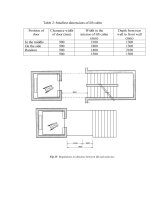
1 ) If the distance b etween outside roof bars is more than 900 mm, the test box length
shall be equal to this distance plus 1 00 mm.
Figure 3 — Test box
6
© BSI 09- 1 999
Li cen sed Copy: Lon d on Sou th Ban k U n i versi ty, Lon d on Sou th Ban k U n i versi ty, Sat Dec 09 02: 08: 52 G M T+00: 00 2006, U n con trol l ed Copy, (c) BSI
BS AU 266-1 :1 996
1 ) In accordance with mounting instructions or 700 mm b y default.
Figure 4 — Test box location and strapping
© BSI 09- 1 999
7
Li cen sed Copy: Lon d on Sou th Ban k U n i versi ty, Lon d on Sou th Ban k U n i versi ty, Sat Dec 09 02: 08: 52 G M T+00: 00 2006, U n con trol l ed Copy, (c) BSI
BS AU 266-1 :1 996
Figure 5 — Deflection measuring point
8
© BSI 09- 1 999
Li cen sed Copy: Lon d on Sou th Ban k U n i versi ty, Lon d on Sou th Ban k U n i versi ty, Sat Dec 09 02: 08: 52 G M T+00: 00 2006, U n con trol l ed Copy, (c) BSI
BS AU 266-1 :1 996
NO TE
The force is ap p lied in the direction of vehicle movem ent, at the centre of the tes t b ox front face.
Figure 6 —
Figure 7 —
© BS I 0 9- 1 99 9
F
l
F
lq
application point
application point
9
Li cen sed Copy: Lon d on Sou th Ban k U n i versi ty, Lon d on Sou th Ban k U n i versi ty, Sat Dec 09 02: 08: 52 G M T+00: 00 2006, U n con trol l ed Copy, (c) BSI
BS AU 266-1 :1 996
Figure 8 —
10
F
a
and
0, 5
F
a
application points
© BS I 0 9 - 1 99 9
Li cen sed Copy: Lon d on Sou th Ban k U n i versi ty, Lon d on Sou th Ban k U n i versi ty, Sat Dec 09 02: 08: 52 G M T+00: 00 2006, U n con trol l ed Copy, (c) BSI
BS AU 266-1 :1 996
Annex A (normative)
Approval/rej ection procedure
© BSI 09- 1 999
11
Li cen sed Copy: Lon d on Sou th Ban k U n i versi ty, Lon d on Sou th Ban k U n i versi ty, Sat Dec 09 02: 08: 52 G M T+00: 00 2006, U n con trol l ed Copy, (c) BSI
BS AU 266-1 :1 996
Annex B (normative)
Tightening torques for fixing roof bars
Torque
Type of fixing
N·m
Hand nut/screw diameter less than 35 mm
2
Hand nut/screw diameter 35 mm to less than 45 mm
3
Hand nut/screw diameter 45 mm to less than 55 mm
4
Hand nut/screw diameter 55 mm to less than 65 mm
5
Slotted head screw M6
3
Slotted head screw M8
4
a
CHC, VH, TORX M6 screw
5
CHC, VH, TORXa M8 screw
6
Hexagon nut M6
5
Hexagon nut M8
6
Butterfly nut M6
2
Butterfly nut M8
3
a
TORX is a trade- name. This information is given for the convenience of users of this International Standard and does not
constitute an endorsement by ISO of the product named. Equivalent products may be used if they can be shown to lead to the
same results.
Annex C (informative)
Determination of allowable additional mass
The maximum load to be carried on roof bars shall be limited such that
— the maximum allowable mass on the vehicle roof,
— the maximum allowable mass on the set of roof bars, and
— the maximum total mass of the vehicle,
are not exceeded.
Calculation examples are given below.
Values in kilograms
Ref.
a
Items to be considered
Maximum allowable mass on the vehicle roof defined
Example No. 1
Example No. 2
Example No. 3
60
75
1 00
350
500
650
75
50
1 00
300
380
450
10
5
20
0
50
75
a – e
50
70
80
c
75
50
1 00
b – (d + e + f)
40
65
1 05
40
50
80
by the vehicle manufacturer
b
Payload (as defined by vehicle manufacturer)
c
Maximum load which carrier system can accept
d
Assumed interior load (75 kg/passenger + luggage)
e
Mass of carrier system
f
Maximum allowable load on towing hook
g
Maximum allowable load on roof carrier system —
the lowest of the following calculated values:
that is
12
© BSI 09- 1 999
Li cen sed Copy: Lon d on Sou th Ban k U n i versi ty, Lon d on Sou th Ban k U n i versi ty, Sat Dec 09 02: 08: 52 G M T+00: 00 2006, U n con trol l ed Copy, (c) BSI
BS AU 266-1 :1 996
List of references
See national foreword.
© BSI 09- 1 999
Li cen sed Copy: Lon d on Sou th Ban k U n i versi ty, Lon d on Sou th Ban k U n i versi ty, Sat Dec 09 02: 08: 52 G M T+00: 00 2006, U n con trol l ed Copy, (c) BSI
BS AU 266-1 :
1 996
ISO 1 1 1 5 4-1 :
BSI — British Standards Institution
1 995
BS I is the indep endent national b ody res p ons ib le for p rep aring
Britis h S tandards . It p res ents the UK view on s tandards in E urop e and at the
international level. It is incorp orated b y Royal C harter.
Revisions
Britis h S tandards are up dated b y amendment or revis ion. Us ers of
Britis h S tandards should make s ure that they p oss es s the latest amendments or
editions .
It is the constant aim of BS I to imp rove the quality of our p roducts and services .
We would b e grateful if anyone finding an inaccuracy or amb iguity while us ing
this Britis h S tandard would inform the S ecretary of the technical committee
res p ons ib le, the identity of which can b e found on the inside front cover.
Tel: 02 0 89 96 90 00. Fax: 02 0 89 96 7 40 0 .
BS I offers memb ers an individual up dating s ervice called PLUS which ens ures
that s ub s crib ers automatically receive the lates t editions of s tandards .
Buying standards
O rders for all BS I, international and foreign s tandards p ub lications s hould b e
addres s ed to C us tomer S ervices. Tel: 0 2 0 899 6 9 00 1 . Fax: 0 2 0 899 6 7001 .
In res p ons e to orders for international standards , it is BS I p olicy to sup p ly the
BS I imp lementation of thos e that have b een p ub lis hed as Britis h S tandards,
unless otherwis e requested.
Information on standards
BS I p rovides a wide range of information on national, E urop ean and
international standards through its Lib rary and its Technical H elp to E xp orters
S ervice. Various BS I electronic information s ervices are also availab le which give
details on all its p roducts and s ervices . C ontact the Information C entre.
Tel: 02 0 89 96 71 1 1 . Fax: 02 0 89 96 7 048.
S ub s crib ing memb ers of BS I are kep t up to date with s tandards develop ments
and receive sub s tantial discounts on the p urchase p rice of s tandards. For details
of thes e and other b enefits contact Memb ership Adminis tration.
Tel: 02 0 89 96 70 02 . Fax: 02 0 89 96 7 00 1 .
Copyright
C op yright s ub s is ts in all BS I p ub lications . BS I als o holds the cop yright, in the
UK, of the p ub lications of the internationalstandardization b odies . E xcep t as
p ermitted under the C op yright, D es igns and Patents Act 1 988 no extract may b e
rep roduced, s tored in a retrieval s ystem or transmitted in any form or b y any
means – electronic, p hotocop ying, recording or otherwis e – without p rior written
p ermis s ion from BS I.
This does not p reclude the free us e, in the cours e of imp lementing the standard,
of necess ary details such as s ymb ols, and size, typ e or grade designations. If thes e
details are to b e used for any other p urp os e than imp lementation then the p rior
written p ermiss ion of BS I must b e ob tained.
If p ermis sion is granted, the terms may include royalty p ayments or a licensing
agreement. D etails and advice can b e ob tained from the C op yright Manager.
BS I
3 89 C his wick H igh Road
London
W4 4AL
Tel: 02 0 89 96 70 7 0.