Ultraviolet amplified spontaneous emission from self organized network of zinc oxide nanofibers
Bạn đang xem bản rút gọn của tài liệu. Xem và tải ngay bản đầy đủ của tài liệu tại đây (184.48 KB, 4 trang )
This document is downloaded from DR-NTU, Nanyang Technological
University Library, Singapore.
Title
Ultraviolet amplified spontaneous emission from self-
organized network of zinc oxide nanofibers.
Author(s)
Xu, Chunxiang.; Sun, Xiaowei.; Yuen, Clement.; Chen, B.
J.; Yu, S. F.; Dong, Zhili.
Citation
Xu, C., Sun, X., Yuen, C., Chen, B. J., Yu, S. F. & Dong,
Z. L. (2005). Ultraviolet amplified spontaneous emission
from self-organized network of zinc oxide nanofibers.
Applied Physics Letters, 86.
Date 2005
URL />Rights
© 2005 American Institute of Physics. This paper was
published in Applied Physics Letters and is made
available as an electronic reprint (preprint) with
permission of American Institute of Physics. The paper
can be found at: [DOI:
One print or
electronic copy may be made for personal use only.
Systematic or multiple reproduction, distribution to
multiple locations via electronic or other means,
duplication of any material in this paper for a fee or for
commercial purposes, or modification of the content of
the paper is prohibited and is subject to penalties under
law.
Ultraviolet amplified spontaneous emission from self-organized network
of zinc oxide nanofibers
C. X. Xu,
a)
X. W. Sun,
b)
Clement Yuen, B. J. Chen, and S. F. Yu
School of Electric and Electronic Engineering, Nanyang Technological University, Nanyang Avenue,
Singapore 639798, Singapore
Z. L. Dong
School of Materials Engineering, Nanyang Technological University, Nanyang Avenue, Singapore 639798,
Singapore
(Received 20 August 2004; accepted 5 November 2004; published online 27 December 2004)
Self-organized zinc oxide (ZnO) nanofiber network with six-fold symmetry was fabricated on
ZnO-buffered (0001) sapphire substrate with patterned gold catalyst by vapor-phase transport
method. From the ZnO buffer layer, hexagonal ZnO nanorods with identical in-plane structure grew
epitaxially along [0001] orientation to form vertical stems. The nanofiber branches grew
horizontally from six side-surfaces of the vertical stem along ͓01
10͔ and other equivalent directions.
The aligned network structure constructed a waveguide array with optical gain. Ultraviolet amplified
spontaneous emission was observed along the side-branching nanofibers when the aligned ZnO
network was excited by a frequency-tripled Nd:YAG laser. © 2005 American Institute of Physics.
[DOI: 10.1063/1.1847716]
One-dimensional nanostructural materials have attracted
great interest because of their unique properties and promis-
ing applications in electronics, photonics, and biochemistry.
How to organize the nanostructural materials into functional
nanodevices is the most critical issue faced by researchers.
Lieber’s group
1
has developed a fluidic alignment technol-
ogy to assemble one-dimensional nanostructures. Electron
beam lithography
2
and scanning probe microscopy
3
have
also been utilized to prepare the nanowebs through the so-
called top-down approach. Though various desired structures
could be fabricated in principle through these advanced
tools, the fabrication process is relatively slow and inconve-
nient. Self-assembly is an economic and convenient ap-
proach to fabricated nanostructural networks. So far, the al-
ternative self-assembling approaches include diffusion-
controlled aggregation,
4
nanocluster
5
and template-assisted
growth,
6
atomic adsorption along stress lines on flat surface,
7
dealloying a chemical etched Al–Si thin film,
8
surfactant-
induced mesoscopic organization,
9
and hydrogen/oxygen
plasma exposure.
10
Although various nanomaterials have
been employed in the above-mentioned reports, all reported
nanostructural networks were random.
In recent years, various nanostructural ZnO such as
nanowires,
11
nanotubes,
12
nanoribbons,
13
nanopins,
14
and hi-
erarchical nanorods
15,16
have been fabricated. The aesthetic
morphologies and its wide band gap and strong excitonic
binding energy have trigged great interest in the nanoscience
and nanotechnology based on ZnO. In this letter, we report a
six-fold symmetric self-organized network of ZnO nanofiber
fabricated on sapphire substrate through vapor-phase trans-
port assisted by [0001]-oriented ZnO buffer layer and Au-
patterned catalyst.
One promising application of ZnO is to be used as ultra-
violet light source, such as UV light emitting diodes and
laser diodes. In recent years, the UV laser of ZnO has been
observed in powder, thin film and nanowire samples based
on the positive feedback in random and Fabry–Perot
cavities.
17–19
The amplified spontaneous emission (ASE) has
also been investigated in ZnO powders and patterned films
with incoherent and coherent feedback in the gain media.
20,21
In this letter, we shall also report observation of ASE from
the aligned ZnO network.
Before preparation of ZnO network, a ZnO buffer layer
was fabricated on (0001) sapphire by filtered cathodic
vacuum arc technology.
22,23
Using a copper grid with 400
mesh as the mask, a patterned array of thin gold film was
prepared on the ZnO buffer layer by thermal evaporation.
ZnO nanofiber network was fabricated on the patterned sub-
strate by vapor-phase transport method.
11,14
The growth was
carried out in a quartz tube using a mixture of ZnO and
graphite powders as source materials. The source tempera-
ture was 1100 °C and the growth temperature was about
700 °C. A white layer of product was observed on the col-
lector after sintering for 30 mins.
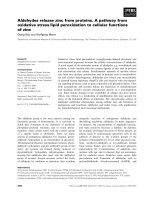
Figure 1 shows the XRD patterns of the ZnO buffer
layer and the nanofiber network. Only (0002) peak was ob-
served from the ZnO thin film, which demonstrates that the
ZnO buffer layer grows along [0001] direction with good
crystal quality. The XRD spectrum illustrates multipeaks af-
ter the ZnO nanostructure was fabricated on the buffer layer.
As indexed in Fig. 1, all diffraction peaks match the wurtzite
ZnO structure with the lattice constants of a=3.250 Å and
c=5.207 Å.
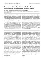
Figure 2(a) shows the scanning electron microscopy
(SEM) image of the product. Due to the catalyst dominated
position-selected growth, the surface was covered with pat-
terned arrays of ZnO nanostructures corresponding to the
inserted gold pattern [insert of Fig. 2(a)]. It is clearly seen
that the nanofibers grow along six specific directions parallel
to the substrate surface. The size of the nanofibers is about
a)
Also with: Department of Electronic Engineering, Southeast University,
Nanjing 210096, P. R. China.
b)
Author to whom correspondence should be addressed; electronic mail:
APPLIED PHYSICS LETTERS 86, 011118 (2005)
0003-6951/2005/86(1)/011118/3/$22.50 © 2005 American Institute of Physics86, 011118-1
Downloaded 24 Feb 2011 to 155.69.4.4. Redistribution subject to AIP license or copyright; see />500–800 nm in diameter and several tens of microns in
length. Each cell is composed of six-fold symmetric
branches that interconnect adjacent cells to form a network
with regular structure. Figure 2(b) shows the enlarged SEM
image of the nanowhisker morphology corresponding to the
center of a cell as circled in Fig. 2(a). Each whisker is com-
posed of a stem with hexagonal cross section and several
branches grown radially around the sides of the stem. It is
noted that the stems are perpendicular to the substrate, and
the branches from either the same or different stems are par-
allel to the substrate along the pre-defined six-fold symmet-
ric directions as indicated by the arrows in Fig. 2(b).
Figures 2(c) and 2(d) show the high resolution transmis-
sion electron microscopy (HRTEM) images taken from dif-
ferent parts of a nanowhisker as inserted between Figs. 2(c)
and 2(d). The lattice fringes of the stem with the d spacing of
0.26 nm match the interspacing of (0002) planes of the
wurtzite ZnO, while the lattice fringes of the branch nanofi-
ber with the d spacing of 0.28 nm coincide with the spacing
of ͑01
10͒ planes. These results demonstrate that the hexago-
nal nanorods grew epitaxially along [0001] direction from
the ZnO buffer layer to form vertically aligned stems with
hexagonal structure, and the branch nanofibers grew around
the side surfaces along ͗01
10͘ orientations to form a six-fold
symmetric structure. The growth mechanism will be ana-
lyzed separately in another paper.
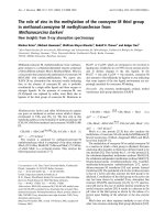
Figure 3 shows the PL spectrum of the ZnO network
excited by 355 nm UV light selected from a Xe lamp. The
PL spectrum contains a strong narrow UV band peaking at
386 nm and a very weak broad green band centered at about
520 nm. The UV emission is originated from excitonic re-
combination corresponding to the band-edge emission of
ZnO and the green one is related to the defects in ZnO such
as oxygen vacancies. Consistent with the results of XRD and
HRTEM, the strong UV and weak green bands imply good
crystal quality and low concentration of defects in the ZnO
network. It is noted that the width of the UV emission band
is narrowed dramatically when the sample was excited by a
strong pulsed Nd:YAG laser (355 nm, 6 ns, and 10 Hz),as
shown in the insert in Fig. 3, which was obtained in a con-
figuration that the direction of the incident laser was along
the stem fibers of the hierarchical structures (perpendicular to
the substrate surface) and the PL signal was measured in the
perpendicular directions around the stems (parallel to the
side branches and substrate). It can be seen from Fig. 3 that
the full width at the half maximum (FWHM) of the sponta-
neous UV emission band excited by the Xe lamp was about
17 nm. However, excited by a frequency-tripled Nd:YAG
laser with a power of 312 kW/cm
2
, an ASE process was
obviously observed, which showed a narrowed UV spectrum
with the FWHM of 3 nm.
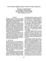
In order to understand the ASE process in the network
structures, we explored the relationship of the output inten-
sity and the spectral FWHM on the excitation intensity (Fig.
4). It can be seen that the output intensity is low and in-
creases slowly with the increase of the pumping power under
300 kW/cm
2
. In this region of pumping power, the UV emis-
sion shows a broad band, for example, the FWHM is about
11 nm at 35 kW/cm
2
. When the excitation intensity was
above 300 kW/cm
2
, the FWHM of the UV spectra quickly
narrowed to 3 nm (insert of Fig. 4) and the output intensity
increases rapidly with the increase of the pumping power. It
is estimated that the threshold of the ASE is about
300 kW/cm
2
. It is worth mentioning that the ASE signal
could hardly be detected if the detector is positioned at an
oblique angle to the substrate, which indicates that the
aligned nanofibers act as waveguides and the positive feed-
back happened in the branching fibers of the ZnO network.
FIG. 1. XRD patterns of ZnO buffer layer and as-grown ZnO nanofiber
network.
FIG. 2. SEM and HRTEM images of the ZnO network. (a) Six-fold sym-
metrically aligned ZnO array corresponding to the inserted gold pattern on
ZnO buffer layer. (b) The enlarged SEM image of the center area of a cell
circled in (a). The arrows drawn in (b) indicate the growth directions of the
branches parallel to the substrate. (c) and (d) The HRTEM images taken
from the inserted stem (left) and the branch (right), respectively.
FIG. 3. PL spectra of the ZnO nanofiber network excited by 355 nm light
from Xe lamp inserted with the normalized UV emission bands excited by
355 nm light from Xe lamp and 312 kW/cm
2
frequency-tripled Nd:YAG
laser as light sources, respectively.
011118-2 Xu
et al.
Appl. Phys. Lett. 86, 011118 (2005)
Downloaded 24 Feb 2011 to 155.69.4.4. Redistribution subject to AIP license or copyright; see />ASE is a light emission process in which spontaneously
emitted photons are amplified by stimulated emission as they
travel through a gain medium.
24
A typical method to obtain
ASE is by fabricating a waveguide array of the gain medium.
For example, Yang et al.
24
fabricated a mesostructural silica
stripe array doped with rhodamine 6G by soft lithography
and obtained ASE with FWHM of 7 nm. Recently, Yu et al.
21
observed ASE with FWHM of 9 nm and threshold of
1.9 MW/cm
2
from ZnO ridge waveguide. In those reports,
an etching process has to be employed to pattern the wave-
guide structure and the width and height of each ridge are
usually about several microns. In the present case, the
aligned array of ZnO is self-organized in six symmetrical
directions and the diameter of the fibers is about several hun-
dreds of nanometers, and the ASE present a FWHM of 3 nm
with a threshold of about 300 kW/cm
2
. The regular struc-
tural ZnO network constructs the aligned waveguide arrays
along the six symmetrical directions (ZnO side branches)
because the refractive index of ZnO (2.1–2.45)
21,25
is higher
than that of air and even sapphire substrate (1.76), therefore,
it is reasonable that the ASE is confined in the branch nanofi-
bers and emits from the ends of them. When the excitation
power excesses the threshold, every photon generated a sec-
ond photon by stimulated emission before leaving the gain
medium. Further increasing the pumping power will trigger a
“chain reaction,” i.e., one photon generates two phontons,
and two photons generate four phontons, etc.
20
The drastic
increase of photon density at the frequency of gain maximum
results in PL intensity enhanced superlinearly and spectral
width narrowed dramatically.
In summary, employing an epitaxial ZnO buffer layer on
sapphire, a regular network of ZnO nanofibers was fabricated
by vapor-phase transport method using the mixture of ZnO
and graphite powders as source materials and patterned-Au
as catalyst. From the buffer layer, the ZnO nanorod grew
epitaxially along [0001] orientation to form a stem with hex-
agonal cross section, while the branch nanofibers grew
around the stem from its six side surfaces to form a hierar-
chical structure with six-fold symmetry. Due to the good
crystal quality, the nanostructural network presented strong
excitonic recombination and weak defect-related recombina-
tion when it was excited by the Xe lamp. The ASE was
observed in the self-organized waveguide array formed by
the aligned branching nanofibers when intense laser light
was vertically pumped into the nanowork. The self-organized
ZnO network with regular structure may be used for elec-
tronic or photonic interconnect and other advanced applica-
tions.
The sponsorships from Research Grant Manpower Fund
(RG51/01) of Nanyang Technological University and Sci-
ence and Engineering Research Council Grant
(#0421010010) from Agency for Science, Technology and
Research (A*STAR), Singapore are gratefully acknowl-
edged.
1
Y. Huang, X. Duan, Q. Wei, and C. M. Leiber, Science 291, 639 (2001).
2
D. R. Cumming, S. Tho, S. P. Beaumont, and J. M. Weaber, Appl. Phys.
Lett. 68,322(1996).
3
P. J. de Pablo, C. G. Navarro, A. Gil, J. Colchero, M. T. Martinez, A. M.
benito, W. K. Maser, J. G. Herrero, and A. M. Baro, Appl. Phys. Lett. 79,
2797 (2001).
4
H. Roder, E. Hahn, H. Brune, J. P. Bucher, and K. Kern, Nature (London)
366, 141 (1993).
5
K. Bromann, C. Felix, H. Brune, W. Harbivh, J. Buttet, and K. Kern,
Science 274, 956 (1996).
6
E. Braun, Y. Eichen, U. Sivan, and G. Yoseph, Nature (London) 391,775
(1998).
7
A. L. Kipp, J. Brandt, L. Tarcak, M. Traving, C. Kreis, and M. Skibowski,
Appl. Phys. Lett. 74, 3053 (1999).
8
M. Paulose, C. A. Grimes, O. K. Varghese, and E. C. Dickey, Appl. Phys.
Lett. 81,153(2002).
9
B. Messer, J. H. Song, M. Huang, Y. Y. Wu, F. Kim, and P. D. Yang, Adv.
Mater. (Weinheim, Ger.) 12, 1526 (2000).
10
U. M. Graham, S. Sharma, M. K. Sunkara, and B. H. Davis, Adv. Funct.
Mater. 13, 567 (2003).
11
C. X. Xu, X. W. Sun, B. J. Chen, P. Shum, S. Li, and X. Hu, J. Appl. Phys.
95, 661 (2004).
12
J. J. Wu, S. C. Liu, C. T. Wu, K. H. Chen, and L. C. Chen, Appl. Phys.
Lett. 81,1312(2002).
13
M. S. Arnld, P. Avouris, Z. W. Pan, and Z. L. Wang, J. Phys. Chem. B
107, 659 (2003).
14
C. X. Xu and X. W. Sun, Appl. Phys. Lett. 83, 3806 (2003).
15
J. Y Lao, J. G. Wen, and Z. F. Ren, Nano Lett. 2, 1287 (2002).
16
P. X. Gao and Z. L. Wang, Appl. Phys. Lett. 84, 2884 (2004).
17
H. Cao, Y. Zhao, S. T. Ho, E. W. Seelig, Q. H. Wang, and R. P. H. Chang,
Phys. Rev. Lett. 82, 2278 (1999).
18
Z. K. Tang, K. L. Wong, P. Yu, M. Kawasaki, A. Ohtomo, H. Koinuma,
and Y. Seqawa, Appl. Phys. Lett. 72,3270(1998).
19
M. H. Huang, S. Mao, H. Feick, H. Yan, Y. Wu, H. Kind, E. Weber, R.
Russo, and P. Yang, Science 292, 1897 (2001).
20
H. Cao, J. Yu, Y. Xu, Y. Ling, A. L. Burin, E. W. Seeling, X. Liu, and R.
P. H. Chang, IEEE J. Quantum Electron. 9, 111 (2003).
21
S. F. Yu, C. Yuen, S. P. Lau, Y. G. Wang, H. W. Lee, and B. K. Tay, Appl.
Phys. Lett. 83, 4288 (2003).
22
B. J. Chen, X. W. Sun, and B. K. Tay, Mater. Sci. Eng., B 106,300
(2004).
23
X. L. Xu, S. P. Lau, and B. T. Tay, Thin Solid Films 398-399,244(2001).
24
P. Yang, G. Wirnsberger, H. C. Huang, S. R. Cordero, M. D. McGehee, B.
Scott. T. Deng, G. M. Whitesides, B. F. Chmelka, S. K. Buratto, and G. D.
Studky, Science 287, 465 (2000).
25
X. W. Sun and H. S. Kwok, J. Appl. Phys. 86,408(1999).
FIG. 4. Dependence of the PL intensity and the narrowing spectra (insert)
on the excitation power of the pumping laser (355 nm frequency-tripled
Nd:YAG).
011118-3 Xu
et al.
Appl. Phys. Lett. 86, 011118 (2005)
Downloaded 24 Feb 2011 to 155.69.4.4. Redistribution subject to AIP license or copyright; see />