Toyota camry 2006 2011 parking brake hệ thống thắng đỗ xe trên toyota camry đời 2006 2011
Bạn đang xem bản rút gọn của tài liệu. Xem và tải ngay bản đầy đủ của tài liệu tại đây (4.56 MB, 66 trang )
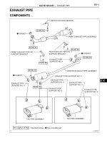
PARKING BRAKE – PARKING BRAKE SYSTEM
PB–1
PB
PARKING BRAKE SYSTEM
PROBLEM SYMPTOMS TABLE
Use the table below to help determine the cause of the
problem. The numbers indicate the priority of the likely cause
of the problem. Check each part in order. If necessary,
replace these parts.
Symptom Suspected area See page
Brake drag
1. Parking brake lever travel (Out of adjustment) PB-1
2. Parking brake pedal travel (Out of adjustment) PB-1
3. Parking brake wire (Sticking) [No. 1 cable] PB-48
4. Parking brake wire (Sticking) [No. 2/No. 3 cable] PB-48
5. Parking brake shoe clearance (Out of adjustment) PB-1
6. Parking brake shoe lining (Cracked or distorted) PB-60
7. Tension or return spring (Damaged) PB-58
PB–2
PARKING BRAKE – PARKING BRAKE SYSTEM
PB
ADJUSTMENT
1. REMOVE REAR WHEEL
2. ADJUST PARKING BRAKE SHOE CLEARANCE
(a) Temporarily install the hub nuts.
(b) Remove the shoe adjusting hole plug.
(c) Turn the shoe adjuster and expand the shoe until
the disc locks.
(d) Turn and contract the shoe adjuster until the disc
can rotate smoothly.
Standard:
Return 8 notches
(e) Check that there is no brake drag against the shoe.
(f) Install the shoe adjusting hole plug.
(g) Remove the hub nuts.
3. INSTALL REAR WHEEL
Torque: 103 N*m (1,050 kgf*cm, 76 ft.*lbf)
4. INSPECT PARKING BRAKE PEDAL TRAVEL (for
Automatic Transaxle)
(a) Fully depress the parking brake pedal and release it
to engage the parking brake.
(b) Depress the pedal to the floor again, and release it
to disengage the parking brake.
(c) Slowly depress the parking brake pedal to the floor,
and count the number of clicks.
Parking brake pedal travel:
7 to 10 notches at 300 N (31 kgf, 67 lbf)
5. ADJUST PARKING BRAKE PEDAL TRAVEL (for
Automatic Transaxle)
(a) Depress the parking brake pedal. Hold the No. 1
wire adjusting nut using a wrench and loosen the
lock nut.
(b) Release the parking brake pedal.
(c) Turn the No. 1 wire adjusting nut until the parking
brake pedal travel meets the above specification.
(d) Hold the No. 1 wire adjusting nut using a wrench or
an equivalent tool and tighten the lock nut.
Torque: 5.4 N*m (55 kgf*cm, 48 in.*lbf)
(e) Count the number of clicks after depressing and
releasing the parking brake pedal 3 or 4 times.
(f) Check whether the parking brake drags.
(g) When operating the parking brake pedal, check that
the parking brake indicator light comes on.
6. INSPECT PARKING BRAKE LEVER TRAVEL (for
Manual Transaxle)
(a) Pull the parking brake lever firmly.
(b) Release the parking brake lock, and return the
parking brake lever to its off position.
Expand
Contract
C131914E01
C107204
No. 1 Wire Adjusting Nut
Lock Nut
C133443E01
PARKING BRAKE – PARKING BRAKE SYSTEM
PB–3
PB
(c) Slowly pull the parking brake lever all the way up,
and count the number of clicks.
Parking brake lever travel:
7 to 9 notches at 200 N (20 kgf, 45 lbf)
7. ADJUST PARKING BRAKE LEVER TRAVEL (for
Manual Transaxle)
(a) Pull up the parking brake lever. Hold the No. 1 wire
adjusting nut using a wrench and loosen the lock
nut.
(b) Release the parking brake lever.
(c) Turn the No. 1 wire adjusting nut until the parking
brake lever travel meets the above specification.
(d) Hold the No. 1 wire adjusting nut using a wrench or
an equivalent tool and tighten the lock nut.
Torque: 5.0 N*m (51 kgf*cm, 44 in.*lbf)
(e) Count the number of clicks after depressing and
releasing the parking brake lever 3 or 4 times.
(f) Check whether the parking brake drags.
(g) When operating the parking brake lever, check that
the parking brake indicator light comes on.
C131910
Lock Nut
Wire Adjusting
No. 1 Nut
C131913E01
PARKING BRAKE – PARKING BRAKE LEVER
PB–3
PB
BRAKEPARKING BRAKE
PARKING BRAKE LEVER
COMPONENTS
FRONT SEAT HEADREST ASSEMBLY
FRONT SEAT HEADREST ASSEMBLY
N*m (kgf*cm, ft.*lbf)
: Specified torque
37 (377, 27)
37 (377, 27)
37 (377, 27)
37 (377, 27)
for Manual Seat:
FRONT SEAT ASSEMBLY LH
FRONT SEAT ASSEMBLY RH
INNER SEAT TRACK
BRACKET COVER LH
INNER SEAT TRACK
BRACKET COVER RH
SEAT TRACK
COVER LH
SEAT TRACK
COVER RH
B132048E01
PB–4
PARKING BRAKE – PARKING BRAKE LEVER
PB
N*m (kgf*cm, ft.*lbf)
: Specified torque
37 (377, 27)
for Power Seat:
FRONT SEAT HEADREST ASSEMBLY
FRONT SEAT HEADREST ASSEMBLY
37 (377, 27)
37 (377, 27)
37 (377, 27)
FRONT SEAT ASSEMBLY LH
FRONT SEAT ASSEMBLY RH
INNER SEAT TRACK
BRACKET COVER LH
INNER SEAT TRACK
BRACKET COVER RH
SEAT TRACK
COVER LH
SEAT TRACK COVER RH
B132047E01
PARKING BRAKE – PARKING BRAKE LEVER
PB–5
PB
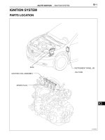
DRIVER SIDE KNEE AIRBAG ASSEMBLY
INSTRUMENT PANEL NO. 2 UNDER
COVER SUB-ASSEMBLY
LOWER INSTRUMENT
PANEL FINISH PANEL LH
LOWER INSTRUMENT
PANEL SUB-ASSEMBLY
UPPER CONSOLE
PANEL SUB-ASSEMBLY
for TMC made:
<A>
<A>
<B>
<B>
<B>
<F>
<F>
<B>
<B> or <C>
N*m (kgf*cm, ft.*lbf)
: Specified torque
10 (102, 7)
C133459E01
PB–6
PARKING BRAKE – PARKING BRAKE LEVER
PB
DRIVER SIDE KNEE AIRBAG ASSEMBLY
INSTRUMENT PANEL NO. 2 UNDER
COVER SUB-ASSEMBLY
LOWER INSTRUMENT
PANEL FINISH PANEL LH
LOWER INSTRUMENT
PANEL SUB-ASSEMBLY
UPPER CONSOLE
PANEL SUB-ASSEMBLY
for TMMK made:
<N>
<N>
<O>
<O>
<O>
<O> or <P>
<O> or <P>
<O>
<O>
N*m (kgf*cm, ft.*lbf)
: Specified torque
10 (102, 7)
C133459E02
PARKING BRAKE – PARKING BRAKE LEVER
PB–7
PB
NO. 1 INSTRUMENT CLUSTER FINISH PANEL GARNISH
NO. 2 INSTRUMENT CLUSTER FINISH PANEL GARNISH
SHIFT LEVER KNOB SUB-ASSEMBLY
UPPER CONSOLE PANEL
UPPER CONSOLE REAR PANEL SUB-ASSEMBLY
FLOOR CARPET BRACKET LH
FLOOR CARPET BRACKET RH
C133456E01
PB–8
PARKING BRAKE – PARKING BRAKE LEVER
PB
CONSOLE BOX
ASSEMBLY
CONSOLE BOX
ASSEMBLY
CONSOLE BOX CARPET
CONSOLE BOX POCKET
NO. 1 CONSOLE BOX INSERT FRONT
NO. 2 CONSOLE BOX INSERT FRONT
for Manual Air
Conditioning System:
for Automatic Air
Conditioning System:
for TMC made:
<F>
<F>
<F>
<F>
<F>
<F>
<F>
<F>
<F>
<F>
<G>
<G>
<G>
<G>
C141955E01
PARKING BRAKE – PARKING BRAKE LEVER
PB–9
PB
CONSOLE BOX
ASSEMBLY
CONSOLE BOX
ASSEMBLY
CONSOLE BOX CARPET
CONSOLE BOX POCKET
NO. 1 CONSOLE BOX INSERT FRONT
NO. 2 CONSOLE BOX INSERT FRONT
for Manual Air
Conditioning System:
for Automatic Air
Conditioning System:
for TMMK made:
<O>
<O>
<O>
<O>
<O>
<O>
<O>
<O>
<S> or <T>
<S> or <T>
<S> or <T>
<S> or <T>
<O>
<O>
C141955E02
PB–10
PARKING BRAKE – PARKING BRAKE LEVER
PB
COWL SIDE TRIM
SUB-ASSEMBLY LH
COWL SIDE TRIM SUB-ASSEMBLY RH
FRONT DOOR OPENING
TRIM WEATHERSTRIP LH
FRONT DOOR OPENING
TRIM WEATHERSTRIP RH
FRONT DOOR SCUFF PLATE LH
FRONT DOOR SCUFF PLATE RH
REAR DOOR OPENING
TRIM WEATHERSTRIP LH
REAR DOOR OPENING
TRIM WEATHERSTRIP RH
REAR DOOR SCUFF PLATE LH
REAR DOOR SCUFF PLATE RH
FRONT FLOOR CARPET ASSEMBLY
LUGGAGE DOOR
LOCK OPEN LEVER
SUB-ASSEMBLY
CROSS MEMBER FLOOR NO. 4
REINFORCEMENT SUB-ASSEMBLY
LOWER CENTER PILLAR GARNISH LH
LOWER CENTER PILLAR GARNISH RH
C132673E01
PARKING BRAKE – PARKING BRAKE LEVER
PB–11
PB
PARKING BRAKE LEVER
SUB-ASSEMBLY
PARKING BRAKE
SWITCH ASSEMBLY
N*m (kgf*cm, ft.*lbf)
: Specified torque * For TMC made ** For TMMK made
1.0 (10, 9.0 in.*lbf)
5.0 (51, 44 in.*lbf)
21 (214, 15)*
22 (224, 16)**
21 (214, 15)*
22 (224, 16)**
NO. 1 WIRE ADJUSTING NUT
PARKING BRAKE EQUALIZER
NO. 1 PARKING BRAKE
CABLE ASSEMBLY
NO. 2 PARKING BRAKE
CABLE ASSEMBLY
NO. 3 PARKING
BRAKE CABLE
ASSEMBLY
C132672E01
PB–12
PARKING BRAKE – PARKING BRAKE LEVER
PB
REMOVAL
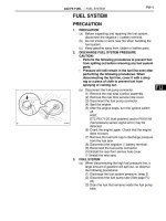
1. PRECAUTION
(See page IP-1)
2. DISCONNECT CABLE FROM NEGATIVE BATTERY
TERMINAL (for Manual Seat)
CAUTION:
Wait for 90 seconds after disconnecting the cable to
prevent the airbag working. (See page RS-1)
3. REMOVE FRONT SEAT ASSEMBLY LH (for Manual
Seat)
HINT:
Refer to the procedures up to "REMOVE FRONT SEAT
ASSEMBLY (for Manual Seat)". (See page SE-16)
4. REMOVE FRONT SEAT ASSEMBLY RH (for Manual
Seat)
HINT:
Use the same procedures for the RH side and the LH
side.
5. REMOVE FRONT SEAT ASSEMBLY LH (for Power
Seat)
HINT:
Refer to the procedures up to "REMOVE FRONT SEAT
ASSEMBLY (for Power Seat)". (See page SE-30)
6. REMOVE FRONT SEAT ASSEMBLY RH (for Power
Seat)
HINT:
Use the same procedures for the RH side and the LH
side.
7. REMOVE COWL SIDE TRIM SUB-ASSEMBLY LH (See
page IR-25)
8. REMOVE COWL SIDE TRIM SUB-ASSEMBLY RH
(See page IR-26)
9. REMOVE INSTRUMENT PANEL NO. 2 UNDER
COVER SUB-ASSEMBLY (See page IP-23)
10. REMOVE LOWER INSTRUMENT PANEL FINISH
PANEL LH (for TMC Made) (See page IP-20)
11. REMOVE LOWER INSTRUMENT PANEL FINISH
PANEL LH (for TMMK Made) (See page IP-21)
12. REMOVE DRIVER SIDE KNEE AIRBAG ASSEMBLY
(See page RS-370)
13. REMOVE LOWER INSTRUMENT PANEL SUB-
ASSEMBLY (for TMC Made) (See page IP-23)
14. REMOVE LOWER INSTRUMENT PANEL SUB-
ASSEMBLY (for TMMK Made) (See page IP-24)
15. REMOVE SHIFT LEVER KNOB SUB-ASSEMBLY (See
page IP-24)
PARKING BRAKE – PARKING BRAKE LEVER
PB–13
PB
16. REMOVE NO. 1 INSTRUMENT CLUSTER FINISH
PANEL GARNISH (See page IP-24)
17. REMOVE NO. 2 INSTRUMENT CLUSTER FINISH
PANEL GARNISH (See page IP-25)
18. REMOVE UPPER CONSOLE PANEL (See page IP-25)
19. REMOVE UPPER CONSOLE REAR PANEL SUB-
ASSEMBLY (See page IP-26)
20. REMOVE UPPER CONSOLE PANEL SUB-ASSEMBLY
(for TMC Made) (See page IP-27)
21. REMOVE UPPER CONSOLE PANEL SUB-ASSEMBLY
(for TMMK Made) (See page IP-27)
22. REMOVE CONSOLE BOX POCKET (See page IP-28)
23. REMOVE CONSOLE BOX CARPET (See page IP-28)
24. REMOVE CONSOLE BOX ASSEMBLY (for TMC
Made) (See page IP-28)
25. REMOVE CONSOLE BOX ASSEMBLY (for TMMK
Made) (See page IP-29)
26. REMOVE NO. 2 CONSOLE BOX INSERT FRONT (for
TMC Made) (See page IP-29)
27. REMOVE NO. 2 CONSOLE BOX INSERT FRONT (for
TMMK Made) (See page IP-30)
28. REMOVE NO. 1 CONSOLE BOX INSERT FRONT (for
TMC Made) (See page IP-30)
29. REMOVE NO. 1 CONSOLE BOX INSERT FRONT (for
TMMK Made) (See page IP-30)
30. REMOVE FLOOR CARPET BRACKET LH (See page
AC-155)
31. REMOVE FLOOR CARPET BRACKET RH (See page
AC-155)
32. REMOVE FRONT DOOR SCUFF PLATE LH (See page
IR-24)
33. REMOVE FRONT DOOR OPENING TRIM
WEATHERSTRIP LH
34. REMOVE REAR DOOR SCUFF PLATE LH (See page
IR-24)
35. REMOVE REAR DOOR OPENING TRIM
WEATHERSTRIP LH
36. REMOVE LOWER CENTER PILLAR GARNISH LH
(See page IR-25)
37. REMOVE FRONT DOOR SCUFF PLATE RH (See page
IR-26)
38. REMOVE FRONT DOOR OPENING TRIM
WEATHERSTRIP RH
PB–14
PARKING BRAKE – PARKING BRAKE LEVER
PB
39. REMOVE REAR DOOR SCUFF PLATE RH (See page
IR-24)
40. REMOVE REAR DOOR OPENING TRIM
WEATHERSTRIP RH
41. REMOVE LOWER CENTER PILLAR GARNISH RH
(See page IR-26)
42. REMOVE LUGGAGE DOOR LOCK OPEN LEVER
SUB-ASSEMBLY
(a) Remove the screw.
(b) Disengage the claw and remove the luggage door
open lever sub-assembly.
43. REMOVE FRONT FLOOR CARPET ASSEMBLY
(a) Disengage the 6 clamps and the 2 claws.
(b) Turn back the front floor carpet assembly until the
bolts of the cross member floor No. 4 reinforcement
sub-assembly can be seen.
44. REMOVE CROSS MEMBER FLOOR NO. 4
REINFORCEMENT SUB-ASSEMBLY
(a) Remove the 8 bolts and the cross member floor No.
4 reinforcement sub-assembly.
C132659
Clamp
Clamp
C132661E01
C132658
PARKING BRAKE – PARKING BRAKE LEVER
PB–15
PB
45. SEPARATE NO. 3 PARKING BRAKE CABLE
ASSEMBLY
(a) Separate the No. 3 parking brake cable assembly
from the parking brake equalizer.
46. SEPARATE NO. 2 PARKING BRAKE CABLE
ASSEMBLY
Separate the No. 2 parking brake cable assembly from
the parking brake equalizer.
47. REMOVE PARKING BRAKE EQUALIZER
(a) Slide the rubber boot as shown in the illustration.
(b) Remove the parking brake equalizer from the No. 1
parking brake cable assembly.
48. REMOVE PARKING BRAKE LEVER SUB-ASSEMBLY
(a) Disconnect the parking brake switch connector.
(b) Remove the 2 bolts, the clip, and the parking brake
lever.
C138184
C138185
C138196
C132657
C131911
PB–16
PARKING BRAKE – PARKING BRAKE LEVER
PB
DISASSEMBLY
1. REMOVE NO. 1 PARKING BRAKE CABLE
ASSEMBLY
(a) Using a screwdriver, pull up the parking brake lever
claw.
(b) Remove the lock nut, the No. 1 wire adjusting nut,
and the No. 1 parking brake cable assembly from
the parking brake lever sub-assembly.
2. REMOVE PARKING BRAKE SWITCH ASSEMBLY
(a) Remove the screw and the parking brake switch
assembly.
REASSEMBLY
1. INSTALL PARKING BRAKE SWITCH ASSEMBLY
(a) Install the parking brake switch assembly with the
screw.
Torque: 1.0 N*m (10 kgf*cm, 9.0 in.*lbf)
2. INSTALL NO. 1 PARKING BRAKE CABLE ASSEMBLY
(a) Pass the No. 1 parking brake cable assembly
through the parking brake lever sub-assembly.
(b) Temporarily tighten the lock nut and the No. 1 wire
adjusting nut.
NOTICE:
Fully tighten the lock nut when adjusting the
parking brake lever travel.
Torque: 5.0 N*m (51 kgf*cm, 44 in.*lbf)
C131912
No. 1 Wire
Adjusting Nut
Lock Nut
C132670E01
C132654
C132654
No. 1 Wire
Adjusting Nut
Lock Nut
C132670E01
PARKING BRAKE – PARKING BRAKE LEVER
PB–17
PB
(c) Bend the parking brake lever claw.
INSTALLATION
1. INSTALL PARKING BRAKE LEVER SUB-ASSEMBLY
(a) Install the parking brake lever sub-assembly with
the 2 bolts and the clip.
Torque: for TMC made
21 N*m (214 kgf*cm, 15 ft.*lbf)
for TMMK made
22 N*m (224 kgf*cm, 16 ft.*lbf)
(b) Connect the parking brake switch connector.
2. INSTALL PARKING BRAKE EQUALIZER
(a) Install the parking brake equalizer to the No. 1
parking brake cable assembly.
(b) Slide the rubber boot back as shown in the
illustration.
3. INSTALL NO. 2 PARKING BRAKE CABLE ASSEMBLY
(a) Connect the No. 2 parking brake cable assembly to
the parking brake equalizer.
C132671
C131911
C132657
C132656
C138185
PB–18
PARKING BRAKE – PARKING BRAKE LEVER
PB
4. INSTALL NO. 3 PARKING BRAKE CABLE ASSEMBLY
(a) Connect the No. 3 parking brake cable assembly to
the parking brake equalizer.
5. INSTALL CROSS MEMBER FLOOR NO. 4
REINFORCEMENT SUB-ASSEMBLY
(a) Install the cross member floor No. 4 reinforcement
sub-assembly with the 8 bolts.
6. INSTALL FRONT FLOOR CARPET ASSEMBLY
(a) Engage the 6 clamps and the 2 claws and install the
front floor carpet assembly.
7. INSTALL LUGGAGE DOOR LOCK OPEN LEVER
SUB-ASSEMBLY
(a) Engage the claw and install the luggage door open
lever sub-assembly with the screw.
8. INSTALL LOWER CENTER PILLAR GARNISH LH
(See page IR-53)
9. INSTALL REAR DOOR OPENING TRIM
WEATHERSTRIP LH (See page IR-55)
10. INSTALL REAR DOOR SCUFF PLATE LH (See page
IR-56)
C138184
C132658
Clamp
Clamp
C132661E01
C132659
PARKING BRAKE – PARKING BRAKE LEVER
PB–19
PB
11. INSTALL FRONT DOOR OPENING TRIM
WEATHERSTRIP LH (See page IR-54)
12. INSTALL FRONT DOOR SCUFF PLATE LH (See page
IR-54)
13. INSTALL LOWER CENTER PILLAR GARNISH RH
(See page IR-54)
14. INSTALL REAR DOOR OPENING TRIM
WEATHERSTRIP RH (See page IR-56)
15. INSTALL REAR DOOR SCUFF PLATE RH (See page
IR-56)
16. INSTALL FRONT DOOR OPENING TRIM
WEATHERSTRIP RH (See page IR-55)
17. INSTALL FRONT DOOR SCUFF PLATE RH (See page
IR-55)
18. INSTALL FLOOR CARPET BRACKET LH
19. INSTALL FLOOR CARPET BRACKET RH
20. INSTALL NO. 2 CONSOLE BOX INSERT FRONT (for
TMC Made) (See page IP-50)
21. INSTALL NO. 2 CONSOLE BOX INSERT FRONT (for
TMMK Made) (See page IP-50)
22. INSTALL NO. 1 CONSOLE BOX INSERT FRONT (for
TMC Made) (See page IP-49)
23. INSTALL NO. 1 CONSOLE BOX INSERT FRONT (for
TMMK Made) (See page IP-50)
24. INSTALL CONSOLE BOX ASSEMBLY (for TMC Made)
(See page IP-51)
25. INSTALL CONSOLE BOX ASSEMBLY (for TMMK
Made) (See page IP-51)
26. INSTALL CONSOLE BOX CARPET (See page IP-51)
27. INSTALL CONSOLE BOX POCKET (See page IP-51)
28. INSTALL UPPER CONSOLE PANEL SUB-ASSEMBLY
(for TMC Made) (See page IP-52)
29. INSTALL UPPER CONSOLE PANEL SUB-ASSEMBLY
(for TMMK Made) (See page IP-52)
30. INSTALL UPPER CONSOLE REAR PANEL SUB-
ASSEMBLY (See page IP-53)
31. INSTALL UPPER CONSOLE PANEL (See page IP-54)
32. INSTALL NO. 1 INSTRUMENT CLUSTER FINISH
PANEL GARNISH (See page IP-55)
33. INSTALL NO. 2 INSTRUMENT CLUSTER FINISH
PANEL GARNISH (See page IP-54)
34. INSTALL SHIFT LEVER KNOB SUB-ASSEMBLY (See
page IP-55)
PB–20
PARKING BRAKE – PARKING BRAKE LEVER
PB
35. INSTALL LOWER INSTRUMENT PANEL SUB-
ASSEMBLY (for TMC Made) (See page IP-55)
36. INSTALL LOWER INSTRUMENT PANEL SUB-
ASSEMBLY (for TMMK Made) (See page IP-56)
37. INSTALL INSTRUMENT PANEL NO. 2 UNDER COVER
SUB-ASSEMBLY (See page IP-56)
38. INSTALL DRIVER SIDE KNEE AIRBAG ASSEMBLY
(See page RS-370)
39. INSTALL LOWER INSTRUMENT PANEL FINISH
PANEL LH (for TMC Made) (See page IP-58)
40. INSTALL LOWER INSTRUMENT PANEL FINISH
PANEL LH (for TMMK Made) (See page IP-59)
41. INSTALL COWL SIDE TRIM SUB-ASSEMBLY LH (See
page IR-54)
42. INSTALL COWL SIDE TRIM SUB-ASSEMBLY RH (See
page IR-55)
43. INSTALL FRONT SEAT ASSEMBLY LH (for Manual
Seat)
HINT:
Refer to the procedures up to "INSTALL FRONT SEAT
ASSEMBLY (for Manual Seat)". (See page SE-24)
44. INSTALL FRONT SEAT ASSEMBLY RH (for Manual
Seat)
HINT:
Use the same procedures for the RH side and the LH
side.
45. INSTALL FRONT SEAT ASSEMBLY LH (for Power
Seat)
HINT:
Refer to the procedures up to "INSTALL FRONT SEAT
ASSEMBLY (for Power Seat)". (See page SE-41)
46. INSTALL FRONT SEAT ASSEMBLY RH (for Power
Seat)
HINT:
Use the same procedures for the RH side and the LH
side.
47. INSPECT PARKING BRAKE LEVER TRAVEL (See
page PB-2)
48. ADJUST PARKING BRAKE LEVER TRAVEL (See
page PB-2)
49. CONNECT CABLE TO NEGATIVE BATTERY
TERMINAL (for Manual Seat)
50. PERFORM ZERO POINT CALIBRATION AND
SENSITIVITY CHECK
(See page RS-242)
51. INSPECT SRS WARNING LIGHT
52. INSPECT SLIDE ADJUSTER LOCK (for Manual Seat)
PARKING BRAKE – PARKING BRAKE LEVER
PB–21
PB
53. INSPECT FRONT SEAT ASSEMBLY (for Power Seat)
(See page SE-42)
PARKING BRAKE – PARKING BRAKE PEDAL
PB–21
PB
BRAKEPARKING BRAKE
PARKING BRAKE PEDAL
COMPONENTS
COWL SIDE TRIM SUB-ASSEMBLY LH
COWL SIDE TRIM SUB-ASSEMBLY RH
DRIVER SIDE KNEE AIRBAG ASSEMBLY
FRONT DOOR
SCUFF PLATE LH
FRONT DOOR
SCUFF PLATE RH
LOWER INSTRUMENT
PANEL SUB-ASSEMBLY
LOWER INSTRUMENT
PANEL FINISH PANEL LH
INSTRUMENT PANEL
NO. 2 UNDER COVER
SUB-ASSEMBLY
UPPER CONSOLE PANEL
SUB-ASSEMBLY
for TMC made:
<A>
<A>
<B>
<B> or <C>
<B>
<B>
<B>
<F>
<F>
N*m (kgf*cm, ft.*lbf)
: Specified torque
10 (102, 7)
C133466E01
PB–22
PARKING BRAKE – PARKING BRAKE PEDAL
PB
COWL SIDE TRIM SUB-ASSEMBLY LH
COWL SIDE TRIM SUB-ASSEMBLY RH
DRIVER SIDE KNEE AIRBAG ASSEMBLY
FRONT DOOR
SCUFF PLATE LH
FRONT DOOR
SCUFF PLATE RH
LOWER INSTRUMENT
PANEL SUB-ASSEMBLY
LOWER INSTRUMENT
PANEL FINISH PANEL LH
INSTRUMENT PANEL
NO. 2 UNDER COVER
SUB-ASSEMBLY
UPPER CONSOLE PANEL
SUB-ASSEMBLY
for TMMK made:
<N>
<N>
<O> or <P>
<O> or <P>
<O>
<O>
<O>
<O>
<O>
N*m (kgf*cm, ft.*lbf)
: Specified torque
10 (102, 7)
C133466E02
PARKING BRAKE – PARKING BRAKE PEDAL
PB–23
PB
CENTER AIRBAG SENSOR ASSEMBLY
CONSOLE BOX
ASSEMBLY
CONSOLE BOX CARPET
CONSOLE BOX POCKET
NO. 1 CONSOLE BOX INSERT FRONT
NO. 2 CONSOLE
BOX INSERT FRONT
for TMC made:
for Manual Air
Conditioning System:
for Automatic Air
Conditioning System:
N*m (kgf*cm, ft.*lbf)
: Specified torque
13 (133, 10)
18 (184, 13)
with VSC:
CONSOLE BOX
ASSEMBLY
<F>
<F>
<F>
<F>
<F>
<F>
<F>
<F>
<G>
<G>
<F>
<F>
<G>
<G>
YAW RATE AND
ACCELERATION
SENSOR
C141956E01