toyota rav4 1994-2000 steering system - hệ thống lái trên xe toyota rav4 đời 1994-2000
Bạn đang xem bản rút gọn của tài liệu. Xem và tải ngay bản đầy đủ của tài liệu tại đây (1.29 MB, 61 trang )
SR0FC−01
−STEERING STEERING SYSTEM
SR−1
1996 RAV4 (RM447U)
STEERING SYSTEM
PRECAUTION
S Care must be taken to replace parts properly because they could affect the performance of the
steering system and result in a driving hazard.
S The TOYOTA RAV4 is equipped with SRS (Supplemental Restraint System) such as the driver
airbag and front passenger airbag. Failure to carry out service operation in the correct se-
quence could cause the SRS to unexpectedly deployed during servicing, possibly leading to
a serious accident. Before servicing (including removal or installation of parts, inspection or
replacement), be sure to read the precautionary notices in the RS section.
SR0FD−01
SR−2
−STEERING TROUBLESHOOTING
1996 RAV4 (RM447U)
TROUBLESHOOTING
PROBLEM SYMPTOMS TABLE
Use the table below to help you find the cause of the problem. The numbers indicate the priority of the likely
cause of the problem. Check each part in the order shown. If necessary, repair or replace these parts.
Symptom Suspect Area See page
Hard steering
1. Tires (Improperly inflated)
2. Power steering fluid level (Low)
3. Drive belt (Loose)
4. Front wheel alignment (Incorrect)
5. Steering system joints (Worn)
6. Suspension arm ball joints (Worn)
7. Steering column (Binding)
8. Power steering vane pump
9. Power steering gear
SA−2
SR−5
SR−3
SA−4
−
SA−45
−
SR−31
SR−44
Poor return
1. Tires (Improperly inflated)
2. Front wheel alignment (Incorrect)
3. Steering column (Binding)
4. Power steering gear
SA−2
SA−4
−
SR−44
Excessive play
1. Steering system joints (Worn)
2. Suspension arm ball joints (Worn)
3. Intermediate shaft, Sliding yoke (Worn)
4. Front wheel bearing (Worn)
5. Power steering gear
−
SA−45
−
SA−4
SR−44
Abnormal noise
1. Power steering fluid level (Low)
2. Steering system joints (Worn)
3. Power steering vane pump
4. Power steering gear
SR−5
−
SR−31
SR−44
P06717
SR0FH−01
Z00038
DENSO Borroughs
P06723
CORRECT WRONG WRONG
−STEERING DRIVE BELT
SR−3
1996 RAV4 (RM447U)
DRIVE BELT
INSPECTION
INSPECT DRIVE BELT
(a) Visually check the belt for excessive wear, frayed cords
etc.
If any defect has been found, replace the drive belt.
HINT:
Cracks on the rib side of a belt are considered acceptable. If the
belt has chunks missing from the ribs, it should be replaced.
(b) Using a belt tension gauge, measure the belt tension.
Belt tension gauge:
DENSO BTG−20 (95506−00020)
Borroughs No. BT−33−73F
Drive belt tension:
New belt: 95 − 145 lbf
Used belt: 60 − 100 lbf
If the belt tension is not as specified, adjust it.
HINT:
S ”New belt” refers to a belt which has been used less than
5 minutes on a running engine.
S ”Used belt” refers to a belt which has been used on a run-
ning engine for 5 minutes or more.
S After installing a belt, check that it fits properly in the
ribbed grooves.
S Check with your hand to confirm that the belt has not
slipped out of the groove on the bottom of the pulley.
S After installing a new belt, run the engine for about 5 min-
utes and recheck the belt tension.
SR0FF−01
R11229
Normal Abnormal
SR−4
−STEERING POWER STEERING FLUID
1996 RAV4 (RM447U)
POWER STEERING FLUID
BLEEDING
1. CHECK FLUID LEVEL (See page SR−5)
2. JACK UP FRONT OF VEHICLE AND SUPPORT IT
WITH STANDS
3. TURN STEERING WHEEL
With the engine stopped, turn the wheel slowly from lock to lock
several times.
4. LOWER VEHICLE
5. START ENGINE
Run the engine at idle for a few minutes.
6. TURN STEERING WHEEL
(a) With the engine idling, turn the wheel to left or right full
lock and keep it there for 2−3 seconds, then turn the
wheel to the opposite full lock and keep it there for 2−3 se-
conds.
(b) Repeat (a) several times.
7. STOP ENGINE
8. CHECK FOR FOAMING OR EMULSIFICATION
If the system has to be bled twice specifically because of foam-
ing or emulsification, check for fluid leaks in the system.
9. CHECK FLUID LEVEL (See page SR−5)
SR0FG−01
R00427
R11229
Normal
Abnormal
R11562
Engine Idling
Engine Stopped
5 mm (0.2 in.)
or less
−STEERING POWER STEERING FLUID
SR−5
1996 RAV4 (RM447U)
INSPECTION
1. CHECK FLUID LEVEL
(a) Keep the vehicle level.
(b) With the engine stopped, check the fluid level in the oil
reservoir.
If necessary, add fluid.
Fluid: ATF DEXRON® II or III
HINT:
Check that the fluid level is within the HOT LEVEL range on the
reservoir. If the fluid is cold, check that it is within the COLD
LEVEL range.
(c) Start the engine and run it at idle.
(d) Turn the steering wheel from lock to lock several times to
boost fluid temperature.
Fluid temperature: 80°C (176°F)
(e) Check for foaming or emulsification.
If there is foaming or emulsification, bleed power steering
system (See page SR−4).
(f) With the engine idling, measure the fluid level in the oil
reservoir.
(g) Stop the engine.
(h) Wait a few minutes and remeasure the fluid level in the oil
reservoir.
Maximum fluid level rise: 5 mm (0.20 in.)
If a problem is found, bleed power steering system
(See page SR−4)
(i) Check the fluid level.
W01159
Attachment SST
In
Out
Pressure Feed Tube
SR−6
−STEERING POWER STEERING FLUID
1996 RAV4 (RM447U)
2. CHECK STEERING FLUID PRESSURE
(a) Disconnect the pressure feed tube (See page SR−33)
(b) Connect SST, as shown below.
SST 09640−10010 (09641−01010, 09641−01030,
09641−01060)
NOTICE:
Check that the valve of the SST is in the open position.
(c) Bleed the power steering system (See page SR−4).
(d) Start the engine and run it at idle.
(e) Turn the steering wheel from lock to lock several times to
boost fluid temperature.
Fluid temperature: 80°C (176°F)
Z15498
Oil
Reservoir
PS Vane
Pump
PS Gear
SST
Closed
Z15499
Oil
Reservoir
PS Vane
Pump
PS Gear
SST
Open
Z15500
Oil
Reservoir
PS Vane
Pump
PS Gear
SST
Open
Lock Position
−STEERING POWER STEERING FLUID
SR−7
1996 RAV4 (RM447U)
(f) With the engine idling, close the valve of the SST and ob-
serve the reading on the SST.
Minimum fluid pressure:
7,355 kPa (75 kgf/cm
2
, 1067 psi)
NOTICE:
S Do not keep the valve closed for more than 10 se-
conds.
S Do not let the fluid temperature become too high.
(g) With the engine idling, open the valve fully.
(h) Measure the fluid pressure at engine speeds of 1,000 rpm
and 3,000 rpm.
Difference fluid pressure:
490 kPa (5 kgf/cm
2
, 71 psi) or less
NOTICE:
Do not turn the steering wheel.
(i) With the engine idling and valve fully opened, turn the
steering wheel to full lock.
Minimum fluid pressure:
7,355 kPa (75 kgf/cm
2
, 1067 psi)
NOTICE:
S Do not maintain lock position for more than 10 se-
conds.
S Do not let the fluid temperature become too high.
(j) Disconnect the SST.
(k) Connect the pressure feed tube (See page SR−42).
(l) Bleed the power steering system (See page SR−4).
R10958
SR0FE−01
SR−8
−STEERING AIR CONTROL VALVE
1996 RAV4 (RM447U)
AIR CONTROL VALVE
INSPECTION
INSPECT AIR CONTROL VALVE
(a) Turn the air conditioner switch OFF.
(b) Start the engine and run it at idle.
(c) Full turn the steering wheel.
(d) Check that the engine rpm decreases when the vacuum
hose of the air control valve is pinched.
(e) Check that the engine rpm increases when the hose is re-
leased.
R06184
SR0FI−02
R09732
−STEERING STEERING WHEEL
SR−9
1996 RAV4 (RM447U)
STEERING WHEEL
INSPECTION
1. CHECK STEERING WHEEL FREEPLAY
With the vehicle stopped and tires facing straight ahead, rock
the steering wheel gently back and forth with light finger pres-
sure.
Freeplay should not exceed the maximum.
Maximum freeplay: 30 mm (1.18 in.)
2. CHECK STEERING EFFORT
(a) Center the steering wheel.
(b) Remove the steering wheel pad (See page SR−12).
(c) Start the engine and run it at idle.
(d) Measure the steering effort in both directions.
Reference: 5.9 N·m (60 kgf·cm, 52 in.·lbf)
HINT:
Be sure to consider the tire type, pressure and contact surface
before making your diagnosis.
(e) Torque the steering wheel set nut.
Torque: 34 N·m (350 kgf·cm, 25 ft·lbf)
(f) Install the steering wheel pad (See page SR−19).
SR0F0−03
SR−10
−STEERING NON−TILT STEERING COLUMN
1996 RAV4 (RM447U)
NON−TILT STEERING COLUMN
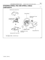
COMPONENTS
−STEERING NON−TILT STEERING COLUMN
SR−11
1996 RAV4 (RM447U)
SR0F1−04
SR−12
−STEERING NON−TILT STEERING COLUMN
1996 RAV4 (RM447U)
REMOVAL
1. REMOVE STEERING WHEEL PAD
NOTICE:
S If the airbag connector is disconnected with the igni-
tion switch at ON or ACC, DTCs will be recorded.
S Never use airbag parts from another vehicle. When
replacing parts, replace with new ones.
(a) Place the front wheels facing straight ahead.
(b) Remove the steering wheel lower No.2 and No.3 covers.
(c) Using a torx socket wrench, loosen the 2 torx screws until
the groove along the screw circumference catches on the
screw case.
(d) Pull the wheel pad out from the steering wheel and dis-
connect the airbag connector.
CAUTION:
S When storing the wheel pad, keep the upper surface
of the pad facing upward.
S Never disassemble the wheel pad.
NOTICE:
When removing the wheel pad, take care not to pull the air-
bag wire harness.
2. REMOVE STEERING WHEEL
(a) Disconnect the connector.
(b) Remove the steering wheel set nut.
(c) Place matchmarks on the steering wheel and main shaft
assembly.
(d) Using SST, remove the wheel.
SST 09950−50010, (09951−05010, 09952−05010,
09953−05020, 09954−05020)
−STEERING NON−TILT STEERING COLUMN
SR−13
1996 RAV4 (RM447U)
3. REMOVE LOWER FINISH PANEL
(a) Remove the 2 screws and disconnect the hood lock con-
trol lever from the panel.
(b) Remove the 2 panel set screws.
4. REMOVE INSTRUMENT PANEL LOWER INSERT
Remove the 3 screws.
5. Non−tilt Steering Column:
REMOVE UPPER AND LOWER COLUMN COVERS
(a) Loosen the 2 column assembly set bolts and 2 nuts.
(b) Remove the 3 screws.
(c) Remove the 3 screws and protector from lower cover.
6. Tilt Steering Column:
REMOVE UPPER AND LOWER COLUMN COVERS
Remove the 3 screws.
7. REMOVE NO.2 HEATER TO REGISTER DUCT
Remove the clip.
8. REMOVE COMBINATION SWITCH WITH SPIRAL
CABLE
(a) Disconnect the connectors.
(b) Disconnect the airbag connector.
(c) Remove the 3 switch set screws.
9. REMOVE SPIRAL CABLE (See page BE−14)
NOTICE:
Do not disassemble the cable or apply oil to it.
W02017
Non−Tilt Steering Column :
A
B
Tilt Steering Column :
Matchmarks
W02018
Matchmarks
SR−14
−STEERING NON−TILT STEERING COLUMN
1996 RAV4 (RM447U)
10. DISCONNECT NO.2 INTERMEDIATE SHAFT
(a) Loosen the bolt A.
(b) Remove the bolt B.
(c) Shift the No.2 intermediate shaft and place matchmarks
on the control valve shaft and No.2 intermediate shaft.
11. REMOVE NO.2 INTERMEDIATE SHAFT
12. REMOVE STEERING COLUMN PROTECTOR
Remove the bolt.
13. REMOVE STEERING COLUMN ASSEMBLY
(a) Disconnect the connectors.
(b) Remove the 2 column assembly set bolts and 2 nuts.
14. Tilt Steering Column:
REMOVE SLIDING YOKE
(a) Remove the bolt.
(b) Shift the sliding yoke and place matchmarks on the main
shaft and sliding yoke.
R10987
Screw Extractor
SR0F2−01
−STEERING NON−TILT STEERING COLUMN
SR−15
1996 RAV4 (RM447U)
DISASSEMBLY
NOTICE:
When using a vise, do not overtighten it.
1. REMOVE STEERING COLUMN UPPER BRACKET
AND STEERING COLUMN UPPER CLAMP
(a) Using a centering punch, mark the center of the 2 ta-
pered−head bolts.
(b) Using a 3−4 mm (0.12−0.16 in.) drill, drill into the 2 bolts.
(c) Using a screw extractor, remove the 2 bolts.
2. REMOVE STEERING MAIN SHAFT ASSEMBLY
(a) Using snap ring expander, remove the snap ring from the
shaft assembly.
(b) Tap out the shaft assembly from the steering column tube.
(c) Using snap ring expander, remove the snap ring from the
shaft assembly.
W01114
SR0F3−03
W01115
ACC
W04213
W04212
SR−16
−STEERING NON−TILT STEERING COLUMN
1996 RAV4 (RM447U)
INSPECTION
1. INSPECT STEERING LOCK OPERATION
Check that the steering lock mechanism operates properly.
2. IF NECESSARY, REPLACE IGNITION KEY CYLINDER
(a) Place the ignition key at the ACC position.
(b) Using a screwdriver, push down the stop pin of the cylin-
der, and pull it out.
(c) Install a new key cylinder.
HINT:
Make sure that the ignition key is at the ACC position.
3. INSPECT IGNITION SWITCH (See page BE−11)
4. IF NECESSARY, REPLACE IGNITION SWITCH
(a) Remove the 2 screws.
(b) Install a new switch with the 2 screws.
5. INSPECT KEY UNLOCK WARNING SWITCH
(See page BE−11)
6. IF NECESSARY, REPLACE KEY UNLOCK WARNING
SWITCH
(a) Remove the 2 screws.
(b) Install a new switch with the 2 screws.
7. IF NECESSARY, REPLACE STEERING MAIN SHAFT
BUSHING
(a) Using a screwdriver, loosen the 3 projections of the bush-
ing, and remove the bushing from the steering column
tube.
(b) Coat the inside of a new bushing with molybdenum disul-
fide lithium base grease.
(c) Align the projections on the bushing with the holes in the
column tube, then install the bushing until the projections
are firmly engaged in the holes.
W01135
Non−tilt Steering Column :
Bearing
Tilt Steering Column :
Bearing
W00088
−STEERING NON−TILT STEERING COLUMN
SR−17
1996 RAV4 (RM447U)
8. INSPECT BEARING
(a) Check the bearing rotation condition and check for abnor-
mal noise.
If the bearing is worn or damaged, replace the steering column
tube.
(b) Coat the bearing with molybdenum disulfide lithium base
grease.
9. Tilt Steering Column:
INSPECT BEARING
Check the bearing of the steering main shaft rotation condition
and check for abnormal noise.
10. Tilt Steering Column:
IF NECESSARY, REPLACE BEARING
(a) Remove the bearing from the steering main shaft.
(b) Coat a new bearing with molybdenum disulfide lithium
base grease.
(c) Install the bearing.
SR0F4−01
W01201
SR−18
−STEERING NON−TILT STEERING COLUMN
1996 RAV4 (RM447U)
REASSEMBLY
NOTICE:
When using a vise, do not overtighten it.
1. INSTALL STEERING MAIN SHAFT ASSEMBLY
(a) Using snap ring expander, install a new snap ring to the
shaft assembly.
(b) Install the shaft assembly into the steering column tube.
(c) Using snap ring expander, install a new snap ring to the
shaft assembly.
2. INSTALL STEERING COLUMN UPPER BRACKET
AND COLUMN UPPER CLAMP
(a) Install the bracket with 2 new tapered−head bolts.
HINT:
Insert the bracket pin into the column tube hole.
(b) Tighten the tapered−head bolts until the bolt heads
breaks off.
SR0F5−03
W02018
−STEERING NON−TILT STEERING COLUMN
SR−19
1996 RAV4 (RM447U)
INSTALLATION
1. Tilt Steering Column:
CONNECT SLIDING YOKE
(a) Align the matchmarks on the main shaft and sliding yoke,
and connect them.
(b) Torque the bolt.
Torque: 35 N·m (360 kgf·cm, 26 ft·lbf)
2. Non−Tilt Steering Column:
INSTALL STEERING COLUMN ASSEMBLY
(a) Temporarily tighten the 2 column assembly set bolts and
2 nuts.
(b) Connect the connectors.
3. Tilt Steering Column:
INSTALL STEERING COLUMN ASSEMBLY
(a) Torque the 2 column assembly set bolts and 2 nuts.
Torque: 25 N·m (260 kgf·cm, 19 ft·lbf)
(b) Connect the connectors.
4. INSTALL STEERING COLUMN PROTECTOR
Torque the bolt.
Torque: 5.0 N·m (50 kgf·cm, 44 in.·lbf)
W02017
Non−tilt Steering Column :
Tilt−Steering Column :
Matchmarks
B
A
SR−20
−STEERING NON−TILT STEERING COLUMN
1996 RAV4 (RM447U)
5. Non−Tilt Steering Column:
INSTALL NO.2 INTERMEDIATE SHAFT
(a) Connect the No.2 intermediate shaft to the main shaft.
(b) Temporarily tighten the bolt A.
6. Tilt Steering Column:
INSTALL No.2 INTERMEDIATE SHAFT
(a) Connect the No.2 intermediate shaft to the sliding yoke.
(b) Temporarily tighten the bolt A.
7. CONNECT NO.2 INTERMEDIATE SHAFT
(a) Align the matchmarks on the No.2 intermediate shaft and
control valve shaft, and connect them.
(b) Torque the bolt B.
Torque: 35 N·m (360 kgf·cm, 26 ft·lbf)
(c) Torque the bolt A.
Torque: 35 N·m (360 kgf·cm, 26 ft·lbf)
8. INSTALL SPIRAL CABLE (See page BE−14)
9. INSTALL COMBINATION SWITCH WITH SPIRAL
CABLE
(a) Tighten the 3 screws.
(b) Connect the connectors.
(c) Connect the airbag connector.
10. INSTALL NO.2 HEATER TO REGISTER DUCT
11. Non−Tilt Steering Column:
INSTALL UPPER AND LOWER COLUMN COVERS
(a) Install the protector to the lower cover and tighten the 3
screws.
(b) Tighten the 3 screws.
(c) Torque the 2 column assembly set bolts and 2 nuts.
Torque: 25 N·m (260 kgf·cm, 19 ft·lbf)
12. Tilt Steering Column:
INSTALL UPPER AND LOWER COLUMN COVERS
(a) Install the protector to the lower cover and tighten the 3
screws.
(b) Tighten the 3 screws.
13. INSTALL INSTRUMENT PANEL LOWER INSERT
Tighten the 3 screws.
14. INSTALL LOWER FINISH PANEL
(a) Tighten the 2 panel set bolts.
(b) Connect the hood lock control lever with the 2 screws.
15. CENTER SPIRAL CABLE
(a) Check that the front wheels are facing straight ahead.
(b) Turn the cable counterclockwise until it locks.
(c) Then rotate the cable clockwise about 2.5 turns to left of
the center.
HINT:
The spiral cable rotates approx. 5 turns maximum.
−STEERING NON−TILT STEERING COLUMN
SR−21
1996 RAV4 (RM447U)
16. INSTALL STEERING WHEEL
(a) Align the matchmarks on the wheel and steering main
shaft assembly.
(b) Torque the wheel set nut.
Torque: 34 N·m (350 kgf·cm, 25 ft·lbf)
(c) Connect the airbag connector.
17. INSTALL STEERING WHEEL PAD
NOTICE:
S Make sure that the pad is installed to the specified
torque.
S If the pad has been dropped, or there are cracks,
dents or other defects in the case or connector, re-
place the wheel pad with a new one.
S When installing the pad, take care that the wiring
does not interfere with other parts and is not pinched
between other parts.
(a) Connect the airbag connector.
(b) Install the pad after confirming that the circumference
groove of the torx screws are caught on the screw case.
(c) Using a torx socket wrench, torque the 2 screws.
Torque: 8.8 N·m (90 kgf·cm, 78 in.·lbf)
(d) Install the steering wheel lower No.2 and No.3 covers.
18. CHECK STEERING WHEEL CENTER POINT
SR0F6−03
SR−22
−STEERING TILT STEERING COLUMN
1996 RAV4 (RM447U)
TILT STEERING COLUMN
COMPONENTS
−STEERING TILT STEERING COLUMN
SR−23
1996 RAV4 (RM447U)
SR0F7−02
SR−24
−STEERING TILT STEERING COLUMN
1996 RAV4 (RM447U)
REMOVAL
(See page SR−12)
SR0F8−04
W01117
W01123
Vinyl Tape
W01124
SST
−STEERING TILT STEERING COLUMN
SR−25
1996 RAV4 (RM447U)
DISASSEMBLY
NOTICE:
When using a vise, do not overtighten it.
1. REMOVE 3 TENSION SPRINGS
HINT:
Remove the springs with the tilt function at maximum tilt up.
2. REMOVE STEERING COLUMN UPPER BRACKET
AND STEERING COLUMN UPPER CLAMP
(See page SR−15)
3. REMOVE COMBINATION SWITCH BRACKET
Remove the 2 bracket set bolts.
4. REMOVE STEERING COLUMN UPPER TUBE WITH
STEERING MAIN SHAFT
(a) Using a hexagon wrench, remove the 2 tilt steering bolts.
(b) Remove the upper tube with the shaft from the steering
column tube.
5. REMOVE TILT LEVER RETAINER
Using screwdriver, remove the retainer from the steering col-
umn upper tube.
NOTICE:
Tape the screwdriver tip before use.
6. REMOVE STEERING MAIN SHAFT
(a) Using SST, compress the compression spring.
SST 09950−40010 (09958−04010)
NOTICE:
Do not bend the universal joint of the shaft more than 20°.
(b) Using a snap ring expander, remove the snap ring from
the shaft.
(c) Remove the shaft from the steering column upper tube.