Daewoo matiz 2000 2013 lighting systems hệ thống chiếu sáng trên xe matiz đời 2000 2013
Bạn đang xem bản rút gọn của tài liệu. Xem và tải ngay bản đầy đủ của tài liệu tại đây (1.02 MB, 27 trang )
DAEWOO M-150 BL2
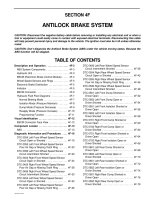
SECTION 9B
LIGHTING SYSTEMS
CAUTION: Disconnect the negative battery cable before removing or installing any electrical unit or when a
tool or equipment could easily come in contact with exposed electrical terminals. Disconnecting this cable
will help prevent personal injury and damage to the vehicle. The ignition must also be in B unless otherwise
noted.
TABLE OF CONTENTS
Description and Operation 9B-2. . . . . . . . . . . . . . . . . .
Headlamps and Parking Lamps 9B-2. . . . . . . . . . . . .
Front Turn Signal Lamps 9B-2. . . . . . . . . . . . . . . . . . .
Rear Fog Lamp 9B-2. . . . . . . . . . . . . . . . . . . . . . . . . . .
Taillamps 9B-2. . . . . . . . . . . . . . . . . . . . . . . . . . . . . . . . .
License Plate Lamp 9B-2. . . . . . . . . . . . . . . . . . . . . . . .
Interior Courtesy Lamp 9B-2. . . . . . . . . . . . . . . . . . . . .
Backup Lamp(s) 9B-2. . . . . . . . . . . . . . . . . . . . . . . . . . .
Daytime Running Lamps (DRL)
(W/Europe Only) 9B-2. . . . . . . . . . . . . . . . . . . . . . . .
Diagnostic Information and Procedures 9B-3. . . . .
Headlamps 9B-3. . . . . . . . . . . . . . . . . . . . . . . . . . . . . . .
Turn Signal Lamps and Hazard Lamps 9B-4. . . . . . .
Stoplamps and Interior Courtesy Lamp 9B-5. . . . . . .
Rear Fog Lamp 9B-6. . . . . . . . . . . . . . . . . . . . . . . . . . .
Repair Instructions 9B-7. . . . . . . . . . . . . . . . . . . . . . . . .
Headlamps 9B-7. . . . . . . . . . . . . . . . . . . . . . . . . . . . . . .
Turn Signal Lamps 9B-8. . . . . . . . . . . . . . . . . . . . . . . .
Side Turn Signal Lamps 9B-8. . . . . . . . . . . . . . . . . . . .
Taillamps Assembly 9B-9. . . . . . . . . . . . . . . . . . . . . . . .
Front Fog Lamp 9B-9. . . . . . . . . . . . . . . . . . . . . . . . . . .
Rear Fog/Backup Lamp(s) 9B-10. . . . . . . . . . . . . . . . .
Center High-Mounted Stoplamp 9B-11. . . . . . . . . . . .
CHMSL Mounting Bracket 9B-12. . . . . . . . . . . . . . . . .
License Plate Lamps 9B-12. . . . . . . . . . . . . . . . . . . . . .
Door Jamb Switch 9B-13. . . . . . . . . . . . . . . . . . . . . . . .
Interior Courtesy Lamp 9B-13. . . . . . . . . . . . . . . . . . . .
Daytime Running Lamp Module
(W/Europe Only) 9B-14. . . . . . . . . . . . . . . . . . . . . . .
Ashtray Lamp 9B-14. . . . . . . . . . . . . . . . . . . . . . . . . . . .
Luggage Room Lamp 9B-15. . . . . . . . . . . . . . . . . . . . .
Specifications 9B-16. . . . . . . . . . . . . . . . . . . . . . . . . . . .
Bulb Usage Chart 9B-16. . . . . . . . . . . . . . . . . . . . . . . .
Schematic and Routing Diagrams 9B-17. . . . . . . . . .
Backup Lamp(s) Circuit 9B-17. . . . . . . . . . . . . . . . . . .
Headlamps Circuit 9B-18. . . . . . . . . . . . . . . . . . . . . . . .
Headlamp Leveling Circuit 9B-19. . . . . . . . . . . . . . . . .
Tail and Licence Plate Lamps Circuit 9B-20. . . . . . . .
Stoplamps Circuit 9B-21. . . . . . . . . . . . . . . . . . . . . . . .
Turn and Hazard Lamps Circuit 9B-22. . . . . . . . . . . .
Interior Courtesy Lamp Circuit 9B-23. . . . . . . . . . . . . .
Front Fog Lamp Circuit 9B-24. . . . . . . . . . . . . . . . . . . .
Rear Fog Lamp Circuit 9B-25. . . . . . . . . . . . . . . . . . . .
Dimmer Control Circuit (Except W/Europe) 9B-26. .
Daytime Running Lamps Circuit
(W/Europe Only) 9B-27. . . . . . . . . . . . . . . . . . . . . . .
9B–2 LIGHTING SYSTEMS
DAEWOO M-150 BL2
DESCRIPTION AND OPERATION
HEADLAMPS AND PARKING LAMPS
The headlamps are controlled by the multifunction lever
located on the left side of the steering column. They will
come on with the ignition switch in any position. Turning
the headlamp switch to the first position turns on the
parking lamps, the license plate lamps and the instru-
ment panel illumination. Turning the switch to the sec-
ond position turns on all of the previous lamps and the
headlamps. Turning the switch to the off position turns
off all the lamps.
The parking lamps can be turned on by turning the light-
ing switch to the first position. The parking lamps can be
turned off by turning the switch to the OFF position.
Headlamp high beam and low beam are also controlled
by this lever. When the headlamps are on, pushing the
lever away from the driver until the switch clicks
changes the lamp from low beam to high beam. An indi-
cator lamp on the instrument cluster assembly will come
on when the high beam headlamps are on. To return the
headlamps to low beam, pull the lever toward the driver.
The headlamps must be aimed for proper illumination of
the road. Headlamp aim should be checked whenever a
new headlamp assembly is installed or service repairs to
the front end area may have disturbed the headlamp as-
sembly or its mountings.
FRONT TURN SIGNAL LAMPS
When the turn signals are activated, the side turn signal
lamps flash to signal a turn. The turn signal works only
when the ignition switch is on.
The turn signals are controlled by the light switch on the
left side of the steering column. Moving the lever all the
way up or down (past the detent) will turn on the turn sig-
nals. When the turn is completed, the lever will return to
horizontal and the turn signals will stop flashing.
For changing lanes or shallow turns where the steering
wheel does not turn far enough to cancel the signal,
move the signal only to the first detent and hold it there.
When the lever is released, it will return to horizontal and
the turn signal will cancel.
REAR FOG LAMP
The rear fog lamp is incorporated in the drive side tail-
lamp assembly and are controlled by the rear fog lamp
switch on the instrument panel. The rear fog lamp can
be turned on only when headlamps are on.
TAILLAMPS
The taillamps, stoplamps, backup lamp(s), rear fog lamp
(if equipped with) and turn signal lamps are one assem-
bly.
Turning on either the headlamps or the parking lamps
will also turn on the taillamps. When the brake pedal is
pushed, the taillamps will glow brighter to serve as sto-
plamps.
The center high-mounted stoplamp is located in the rear
window and will come on when the brake pedal is
pressed.
LICENSE PLATE LAMPS
The license plate lamps will come on when the head-
lamps or the parking lamps are on. The license plate
lamps are mounted on the rear bumper, above the li-
cense plate.
INTERIOR COURTESY LAMP
The courtesy lamp is located on the headliner just be-
fore the front seats. The lamp switch has three posi-
tions. If the switch is in the center position, the lamp will
go on whenever a door is opened and go off when it is
closed. In the ON position, the lamp will stay on until it is
turned off. In the OFF position, the lamp will not come
on, even when a door is opened.
BACKUP LAMP(S)
The backup lamps are located in the rear combination
lamps. They will come on when the transaxle is shifted
into REVERSE. On a vehicle with a manual transaxle,
they are activated by a reverse switch which is part of
the transaxle.
DAYTIME RUNNING LAMPS (DRL)
(W/Europe Only)
The daytime running lamps (DRL) work in conjunction
with the exterior lamps system. When the ignition switch
is turned to the ”II” position with the light switch off, park-
ing, tail, license plate and instrument panel lights illumi-
nate. And, when the engine is started, the headlamps
(low beam) also come on.
They remain on until the ignition switch is turned off or
the light switch is turned on. They revert to normal op-
eration when the light switch is on.
The daytime running lamps (DRL) is optional.
LIGHTING SYSTEMS 9B – 3
DAEWOO M-150 BL2
DIAGNOSTIC INFORMATION AND PROCEDURES
HEADLAMPS
Condition Probable Cause Correction
Low Beam Headlamps Are
Inoperative, High Beam
D Faulty headlamp combination
switch.
D Replace the headlamp
combination switch.
Headlamps Are OK.
D The open circuit or a short circuit
between the fuse Ef10/Ef11 and
the terminal 5 of the headlamp
combination switch.
D Repair or Replace the wiring
harness.
D Fuse Ef10 or Ef11 is blown. D Replace the fuse Ef10 or Ef11
D The open circuit or a short circuit
between the fuse Ef10 or Ef11 and
the terminal 2 of the headlamp
connector.
D Repair or Replace the wiring
harness.
D Headlamp bulb is blown. D Replace the headlamp bulb.
D The open grounds (G101, G102)
circuit.
D Repair or replace the open ground
circuit.
High Beam Headlamps Are
Inoperative, Low Beam
D Faulty headlamp combination
switch.
D Replace the headlamp
combination switch.
Headlamps Are OK.
D The open circuit or a short circuit
between the fuse Ef8/Ef9 and the
terminal 4 of the headlamp
combination switch.
D Repair or Replace the wiring
harness.
D Fuse Ef8 or Ef9 is blown. D Replace the fuse Ef10 or Ef11.
D The open circuit or a short circuit
between the fuse Ef8 or Ef9 and
the terminal 1 of the headlamp
connector.
D Repair or Replace the wiring
harness.
D Headlamp bulb is blown. D Replace the headlamp bulb.
D The open grounds (G101, G102)
circuit.
D Repair or Replace the open
ground circuit.
High Beam and Low Beam
Headlamps Are Inoperative On
Both Left and Right Sides.
D The open circuit or a short circuit
in the power supply circuit to the
fuse Ef18.
D Repair or Replace the wiring
harness.
D Fuse Ef18 is blown. D Replace the fuse Ef18 (20A).
D The open circuit or a short circuit
between the fuse Ef18 and the
terminal 86, 30 of the headlamp
relay.
D Repair or Replace the wiring
harness.
D Faulty headlamp relay. D Replace the headlamp relay.
D The open circuit or a short circuit
between the terminal 87 of the
headlamp relay and the terminal 6
of the headlamp combination
switch.
D Repair or Replace the wiring
harness.
D Faulty headlamp combination
switch.
D Replace the headlamp
combination switch.
D The open ground (G201) circuit. D Repair or Replace the open
ground circuit.
9B–4 LIGHTING SYSTEMS
DAEWOO M-150 BL2
TURN SIGNAL LAMPS AND HAZARD LAMPS
Condition Probable Cause Correction
Turn Signal Lamps and Hazard
Lamps Do Not Work.
D The open circuit or a short circuit
between the power supply circuit
and the fuse Ef2.
D Repair or Replace the wiring
harness.
D Fuse Ef2 is blown. D Replace the fuse Ef2.
D The open circuit or a short circuit
between the fuse Ef2 and the fuse
F12.
D Repair of Replace the wiring
harness.
D Fuse F12 is blown. D Replace the fuse F12.
D The open circuit or a short circuit
between the fuse F12 and the
terminal 8 of the hazard lamp
switch connector.
D Repair or Replace the wiring
harness.
D Faulty hazard lamp switch. D Replace the hazard lamp switch.
D The open circuit or a short circuit
between the terminal 7 of the
hazard lamp switch connector and
the terminal 49 of the turn signal
lamp relay.
D Repair or Replace the wiring
harness.
D The open circuit or a short circuit
between the terminal 49a of the
turn signal lamp relay and the
terminal 9 of the hazard lamp
switch connector.
D Repair or Replace the wiring
harness.
D Faulty turn signal lamp relay. D Replace the turn signal lamp relay.
D The open circuit or a short circuit
between the terminal 49a of the
turn signal lamp relay and the
terminal 2 of the turn signal lamp
switch connector.
D Faulty turn signal lamp switch. D Replace the turn signal lamp
switch.
D The open circuit or a short circuit
between the terminal 1,3 of the
turn signal switch connector and
the terminal 2,5 of each turn signal
lamp connectors.
D Repair or Replace the wiring
harness.
D Turn signal lamp bulb is blown. D Replace the turn signal lamp bulb.
D The open grounds (G101, G102,
G401, G402) circuits.
D Repair or Replace the open
ground circuit.
Hazard Lamps Do Not Operate,
Turn Signals Are OK.
D The open circuit or a short circuit
between the terminal 49a of the
turn signal lamp relay and the
terminal 9 of the hazard lamp
switch connector.
D Repair or Replace the open
circuit.
D The open circuit or a short circuit
between the terminals 5,6 of the
hazard lamp switch connector and
the terminals 2,5 of the turn signal
lamp connectors.
D Repair or Replace the wiring
harness.
LIGHTING SYSTEMS 9B – 5
DAEWOO M-150 BL2
STOPLAMPS AND INTERIOR COURTESY LAMP
Condition Probable Cause Correction
Stoplamps Do Not Work. D Fuse F5 is blown. D Replace the fuse F5.
D The open circuit or a short circuit
between the fuse F11 and the
terminal 2 of the stoplamps switch
connector (For vehicle equipped
with M/T).
D Repair or Replace the wiring
harness.
D Faulty stoplamp switch. D Replace the stoplamp switch.
D The open circuit or a short circuit
between the terminal 1 of the
stoplamp switch connector and
the terminal 3 of the stoplamps
connector (For vehicle equipped
with M/T).
D Repair or Replace the wiring
harness.
D Stoplamp bulb is blown. D Replace the stoplamp bulb.
D The open ground (G401, G402)
circuits.
D Repair or Replace the open
ground circuit.
Interior Courtesy Lamp Does
Not Work.
D The open circuit or a short circuit
in the power supply circuit to the
fuse Ef2.
D Repair or Replace the wring
harness.
D Fuse Ef2 is blown. D Replace the fuse Ef2.
D The open circuit or a short circuit
between the fuse Ef2 and the fuse
F11.
D Repair or Replace the wiring
harness.
D Fuse F11 is blown. D Replace the fuse F11.
D The open circuit or a short circuit
between the fuse F11 and the
terminal 1 of the interior courtesy
lamp connector.
D Repair or Replace the wiring
connector.
D Interior courtesy lamp bulb is
blown.
D Replace the bulb.
D Faulty interior courtesy lamp. D Replace the interior courtesy
lamp.
9B–6 LIGHTING SYSTEMS
DAEWOO M-150 BL2
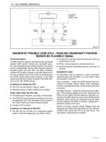
REAR FOG LAMP
Diagnostic Aids: The rear fog lamp will not operate unless the headlamps are ON. If the headlamps are not operat-
ing, repair that problem before attempting to diagnose the rear fog lamp.
Condition Probable Cause Correction
Rear Fog Lamp
Does Not Work.
D The open circuit or a short circuit
between the terminal 87 of the
headlamp relay and terminal 15,30
of the rear fog lamp relay.
D Repair or Replace the wiring
harness.
D Faulty rear fog lamp relay. D Replace the rear fog lamp relay.
D The open circuit or a short circuit
between the terminal 87 of the
rear fog lamp relay and terminal 6
of the rear fog lamp connector.
D Repair or Replace the wiring
harness.
D The open circuit or a short circuit
between the terminal E of the rear
fog lamp relay and terminal 6 of
the rear fog lamp switch.
D Repair or Replace the wiring
harness.
D Faulty rear fog lamp switch. D Replace the rear fog lamp switch.
D The open grounds (G201, G401)
circuits.
D Repair or Replace the open
ground circuit.
D Rear fog lamp bulb is blown. D Replace the rear fog lamp bulb.
LIGHTING SYSTEMS 9B – 7
DAEWOO M-150 BL2
REPAIR INSTRUCTIONS
ON–VEHICLE SERVICE
D209B109
HEADLAMPS
Removal Procedure
1. Support the hood suitably.
2. Disconnect the negative battery cable.
3. Remove the front bumper spacer.
D Remove the bolts (1).
D Remove the front bumper spacer from the bumper
fasia (2).
D19D502A
4. Remove the headlamp.
D Remove the bolts and washer (1).
D Disconnect the electrical connectors.
D Remove the headlamp (2) .
D19D503A
Installation Procedure
1. Install the headlamp with the bolts.
2. Connect the headlamp connector and parking lamp
connector.
3. Install the front bumper spacer with the bolts.
4. Connect the negative battery cable.
9B–8 LIGHTING SYSTEMS
DAEWOO M-150 BL2
D19D505A
TURN SIGNAL LAMPS
Removal Procedure
1. Disconnect the negative battery cable.
2. Remove the front bumper spacer. Refer to Section
9M, Exterior Trim.
3. Remove the turn signal lamps from the front bumper
spacer.
D Disconnect the electrical connector (1).
D Remove the screw (2).
D Remove the turn signal lamp assembly (3).
D19D506A
Installation Procedure
1. Connect the electrical connector.
2. Install the turn signal lamp assembly with the screw.
3. Install the front bumper spacer. Refer to Section 9M,
Exterior Trim.
4. Connect the negative battery cable.
D29B001
SIDE TURN SIGNAL LAMPS
Removal Procedure
1. Disconnect the negative battery cable.
2. Slide the side turn signal lamp rearward.
3. Remove the lamp.
4. Disconnect the electrical connector.
D29B002
Installation Procedure
1. Connect the electrical connector.
2. Install the side turn signal lamp.
3. Connect the negative battery cable.
LIGHTING SYSTEMS 9B – 9
DAEWOO M-150 BL2
D109D507
TAILLAMPS ASSEMBLY
Removal Procedure
1. Disconnect the negative battery cable.
2. Open the tailgate.
3. Remove the luggage compartment wheelhouse trim.
Refer to Section 9G, Interior Trim.
4. Disconnect the electrical connector.
D19D508B
5. Remove the taillamp assembly.
D Remove the screws (1).
D Remove the taillamp (2).
D19D509A
Installation Procedure
1. Install the taillamp assembly with the screws.
2. Connect the electrical connector.
3. Install the luggage compartment wheelhouse trim.
Refer to Section 9G, Interior Trim.
4. Connect the negative battery cable.
D19C501A
FRONT FOG LAMP
Removal Procedure
1. Disconnect the negative battery cable.
2. Raise and suitably support the vehicle.
3. Remove the front wheels.
4. Remove the front wheel house splash shield.
D Remove the clip and bolts.
a. Bolt and clips.
D Remove the wheel house splash shield.
b. Splash shield.
9B–10 LIGHTING SYSTEMS
DAEWOO M-150 BL2
D209B100
5. Remove the front fog lamp.
D Remove the screws (1).
D Disconnect the electrical connector (2).
D Remove the front fog lamp (3).
D209B101
Installation Procedure
1. Install the front fog lamp with the screws.
2. Connect the front fog lamp connector.
3. Install the front wheelhouse splash shields with the
clips and the bolts.
4. Install the front wheels.
5. Lower the vehicle.
6. Connect the negative battery cable.
D19D508C
REAR FOG/BACKUP LAMP(S)
Removal Procedure
1. Disconnect the negative battery cable.
2. Remove the taillamp assembly. Refer to “Taillamps
Assembly” in this section.
3. Remove the bulb(s).
D19D509A
Installation Procedure
1. Install the bulb(s).
2. Install the taillamp assembly. Refer to “Taillamps As-
sembly” in this section.
3. Connect the negative battery cable.
LIGHTING SYSTEMS 9B – 11
DAEWOO M-150 BL2
D29B003B
CENTER HIGH-MOUNTED
STOPLAMP (CHMSL)
Removal Procedure
1. Disconnect the negative battery cable.
2. Open the tailgate.
3. Pry off the tailgate trim panel. Refer to Section 9G In-
terior Trim.
4. Remove the CHMSL cover.
D Remove the screws (1).
D Remove the CHMSL cover (2).
D29B004A
5. Remove the CHMSL and bulb.
D Remove the screws (1).
D29B005B
D Remove the screw from bulb socket (2).
D Remove the CHMSL (3).
D Remove the bulb (4).
D19E554A
Installation Procedure
1. Install the CHMSL bulb.
2. Install the CHMSL with the screws.
3. Install the CHMSL cover with the screws.
4. Install the tailgate trim panel. Refer to Section 9G, In-
terior Trim.
5. Connect the negative battery cable.
9B–12 LIGHTING SYSTEMS
DAEWOO M-150 BL2
D209B102
CHMSL MOUNTING BRACKET
Removal Procedure
1. Disconnect the negative battery cable.
2. Remove the center high–mounted stoplamp
(CHMSL). Refer to “Center High–Mounted Stoplamp”
in this section.
3. Remove the rear window wiper motor assembly. Re-
fer to Section 9D, Wipers/Washer Systems.
4. Remove the CHMSL mounting bracket.
D Remove the bolts (1).
D Remove the CHMSL mounting bracket (2).
D209B103
Installation Procedure
1. Install the CHMSL mounting bracket with the bolts.
2. Install the rear window wiper motor assembly. Refer
to Section 9D, Wipers/Washer Systems.
3 .Install the CHMSL. Refer to “Center High–Mounted
Stoplamp” in this section.
4. Connect the negative battery cable.
D19D510A
LICENSE PLATE LAMPS
Removal Procedure
1. Disconnect the negative battery cable.
2. Remove the license plate lamp from the tailgate han-
dle.
D Remove the screws (1).
D Draw out the license plate lamp (2).
D Remove the license plate lamp bulb (3).
D19D511A
3. Remove the rear window wiper motor assembly. Re-
fer to Section 9D, Wipers/Washer Systems.
4. Disconnect the electrical connector in the tailgate.
5. Remove the tailgate handle. Refer to Section 9M, Ex-
terior Trim.
6. Remove the license plate lamp socket.
D Remove the socket (1).
LIGHTING SYSTEMS 9B – 13
DAEWOO M-150 BL2
D19D512A
Installation Procedure
1. Install the license plate lamp socket.
2. Install the tailgate handle. Refer to Section 9M, Exte-
rior Trim.
3. Connect the electrical connector.
4. Remove the rear window wiper motor assembly. Re-
fer to Section 9D, Wipers/Washer Systems.
5. Install the license plate lamp bulb.
6. Install the license plate lamp with the screws.
7. Connect the negative battery cable.
D109D513
DOOR JAMB SWITCH
Removal Procedure
1. Disconnect the negative battery cable.
2. Remove the door jamb switch.
D Remove the screw (1).
D Disconnect the electrical connector (2).
D Remove the door jamb switch (3).
D109D514
Installation Procedure
1. Install the door jamb switch with the screw.
2. Connect the electrical connector.
3. Connect the negative battery cable.
D19D515A
INTERIOR COURTESY LAMP
Removal Procedure
1. Disconnect the negative battery cable.
2. Remove the interior courtesy lamp.
D Pry off the interior courtesy lamp lens (1).
D Remove the screws (2).
D Disconnect the electrical connector (3).
D Remove the interior courtesy lamp (4).
9B–14 LIGHTING SYSTEMS
DAEWOO M-150 BL2
D109D516
Installation Procedure
1. Connect the electrical connector.
2. Install the interior courtesy lamp with the screws.
3. Install the interior courtesy lamp lens.
4. Connect the negative battery cable.
D29B007
DAYTIME RUNNING LAMP MODULE
(W/Europe Only)
Removal Procedure
1. Disconnect the negative battery cable.
2. Disconnect the electrical connector (1).
3. Remove the screws (2) and the daytime running lamp
module.
D29B008
Installation Procedure
1. Install the daytime running lamp module with the
bolts.
2. Connect the electrical connector.
3. Connect the negative battery cable.
LIGHTING SYSTEMS 9B – 15
DAEWOO M-150 BL2
D209B104
LUGGAGE ROOM LAMP
Removal Procedure
1. Disconnect the negative battery cable.
2. Open the tailgate.
3. Remove the luggage room lamp.
D Remove the luggage room lamp (1).
D Disconnect the electrical connector (2).
D209B105
Installation Procedure
1. Connect the electrical connector.
2. Install the luggage room lamp.
3. Connect the negative battery cable.
9B–16 LIGHTING SYSTEMS
DAEWOO M-150 BL2
SPECIFICATIONS
BULB USAGE CHART
Bulb Replacement Bulb Number
Backup Lamp(s) 21W
Center High Mounted Stoplamp 21W
Headlamps Double 60/55W
Interior Courtesy Lamp 10W
License Plate Lamp 5W
Front Turn Signal Lamps 21W
Rear Fog Lamp 21W
Rear Turn Signal Lamps 21W
Side Marker Turn Signal Lamps 5W
Tail and Stoplamp Double 5/21W, 5W
Parking Lamp 5W
LIGHTING SYSTEMS 9B – 17
DAEWOO M-150 BL2
SCHEMATIC AND ROUTING DIAGRAMS
BACKUP LAMP(S) CIRCUIT
D19D201B
9B–18 LIGHTING SYSTEMS
DAEWOO M-150 BL2
HEADLAMPS CIRCUIT
D19D202B
LIGHTING SYSTEMS 9B – 19
DAEWOO M-150 BL2
HEADLAMP LEVELING CIRCUIT
D19B723B
9B–20 LIGHTING SYSTEMS
DAEWOO M-150 BL2
TAIL AND LICENSE PLATE LAMPS CIRCUIT
D19D203B
LIGHTING SYSTEMS 9B – 21
DAEWOO M-150 BL2
STOPLAMPS CIRCUIT
D19D204B
9B–22 LIGHTING SYSTEMS
DAEWOO M-150 BL2
TURN AND HAZARD LAMPS CIRCUIT
D19D205B
LIGHTING SYSTEMS 9B – 23
DAEWOO M-150 BL2
INTERIOR COURTESY LAMP CIRCUIT
D19D206B
9B–24 LIGHTING SYSTEMS
DAEWOO M-150 BL2
FRONT FOG LAMP CIRCUIT
D19B724A1
LIGHTING SYSTEMS 9B – 25
DAEWOO M-150 BL2
REAR FOG LAMP CIRCUIT
D19B724B