gr - documents
Bạn đang xem bản rút gọn của tài liệu. Xem và tải ngay bản đầy đủ của tài liệu tại đây (4.37 MB, 17 trang )
PDF generated using the open source mwlib toolkit. See for more information.
PDF generated at: Wed, 26 Mar 2014 08:36:10 UTC
GR Documents
Contents
Articles
Motion compensation 1
Motion vector 5
Chroma subsampling 5
References
Article Sources and Contributors 13
Image Sources, Licenses and Contributors 14
Article Licenses
License 15
Motion compensation
1
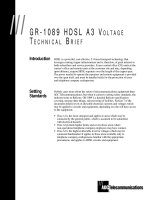
Motion compensation
Visualization of MPEG block motion
compensation. Blocks that moved from one frame
to the next are shown as white arrows, making the
motions of the different platforms and the
character clearly visible.
Motion compensation is an algorithmic technique employed in the
encoding of video data for video compression, for example in the
generation of MPEG-2 files. Motion compensation describes a picture
in terms of the transformation of a reference picture to the current
picture. The reference picture may be previous in time or even from the
future. When images can be accurately synthesised from previously
transmitted/stored images, the compression efficiency can be
improved.
How it works
Motion compensation exploits the fact that, often, for many frames of a
movie, the only difference between one frame and another is the result
of either the camera moving or an object in the frame moving. In
reference to a video file, this means much of the information that
represents one frame will be the same as the information used in the
next frame.
Using motion compensation, a video stream will contain some full (reference) frames; then the only information
stored for the frames in between would be the information needed to transform the previous frame into the next
frame.
Illustrated example
The following is a simplistic illustrated explanation of how motion compensation works. Two successive frames
were captured from the movie Elephants Dream. As can be seen from the images, the bottom (motion compensated)
difference between two frames contains significantly less detail than the prior images, and thus compresses much
better than the rest.
Type Example Frame Description
Original Full original frame, as shown on screen.
Difference Differences between the original frame and the next frame.
Motion
compensated
difference
Differences between the original frame and the next frame, shifted right by 2 pixels.
Shifting the frame compensates for the panning of the camera, thus there is greater overlap
between the two frames.
Motion compensation
2
Motion Compensation in MPEG
In MPEG, images are predicted from previous frames (P frames) or bidirectionally from previous and future frames
(B frames). B frames are more complex because the image sequence must be transmitted/stored out of order so that
the future frame is available to generate the B frames.
[1]
After predicting frames using motion compensation, the coder finds the error (residual) which is then compressed
and transmitted.
Global motion compensation
In global motion compensation, the motion model basically reflects camera motions such as:
•• Dolly - moving the camera forward or backward
•• Track - moving the camera left or right
•• Boom - moving the camera up or down
•• Pan - rotating the camera around its Y axis, moving the view left or right
•• Tilt - rotating the camera around its X axis, moving the view up or down
•• Roll - rotating the camera around the view axis
It works best for still scenes without moving objects.
There are several advantages of global motion compensation:
•• It models the dominant motion usually found in video sequences with just a few parameters. The share in bit-rate
of these parameters is negligible.
•• It does not partition the frames. This avoids artifacts at partition borders.
•• A straight line (in the time direction) of pixels with equal spatial positions in the frame corresponds to a
continuously moving point in the real scene. Other MC schemes introduce discontinuities in the time direction.
MPEG-4 ASP supports GMC with three reference points, although some implementations can only make use of one.
A single reference point only allows for translational motion which for its relatively large performance cost provides
little advantage over block based motion compensation.
Moving objects within a frame are not sufficiently represented by global motion compensation. Thus, local motion
estimation is also needed.
Block motion compensation
In block motion compensation (BMC), the frames are partitioned in blocks of pixels (e.g. macroblocks of 16×16
pixels in MPEG). Each block is predicted from a block of equal size in the reference frame. The blocks are not
transformed in any way apart from being shifted to the position of the predicted block. This shift is represented by a
motion vector.
To exploit the redundancy between neighboring block vectors, (e.g. for a single moving object covered by multiple
blocks) it is common to encode only the difference between the current and previous motion vector in the bit-stream.
The result of this differencing process is mathematically equivalent to a global motion compensation capable of
panning. Further down the encoding pipeline, an entropy coder will take advantage of the resulting statistical
distribution of the motion vectors around the zero vector to reduce the output size.
It is possible to shift a block by a non-integer number of pixels, which is called sub-pixel precision. The in-between
pixels are generated by interpolating neighboring pixels. Commonly, half-pixel or quarter pixel precision (Qpel, used
by H.264 and MPEG-4/ASP) is used. The computational expense of sub-pixel precision is much higher due to the
extra processing required for interpolation and on the encoder side, a much greater number of potential source blocks
to be evaluated.
Motion compensation
3
The main disadvantage of block motion compensation is that it introduces discontinuities at the block borders
(blocking artifacts). These artifacts appear in the form of sharp horizontal and vertical edges which are easily spotted
by the human eye and produce ringing effects (large coefficients in high frequency sub-bands) in the Fourier-related
transform used for transform coding of the residual frames
[citation needed]
.
Block motion compensation divides up the current frame into non-overlapping blocks, and the motion compensation
vector tells where those blocks come from (a common misconception is that the previous frame is divided up into
non-overlapping blocks, and the motion compensation vectors tell where those blocks move to). The source blocks
typically overlap in the source frame. Some video compression algorithms assemble the current frame out of pieces
of several different previously-transmitted frames.
Frames can also be predicted from future frames. The future frames then need to be encoded before the predicted
frames and thus, the encoding order does not necessarily match the real frame order. Such frames are usually
predicted from two directions, i.e. from the I- or P-frames that immediately precede or follow the predicted frame.
These bidirectionally predicted frames are called B-frames. A coding scheme could, for instance, be
IBBPBBPBBPBB.
Variable block-size motion compensation
Variable block-size motion compensation (VBSMC) is the use of BMC with the ability for the encoder to
dynamically select the size of the blocks. When coding video, the use of larger blocks can reduce the number of bits
needed to represent the motion vectors, while the use of smaller blocks can result in a smaller amount of prediction
residual information to encode. Older designs such as H.261 and MPEG-1 video typically use a fixed block size,
while newer ones such as H.263, MPEG-4 Part 2, H.264/MPEG-4 AVC, and VC-1 give the encoder the ability to
dynamically choose what block size will be used to represent the motion.
Overlapped block motion compensation
Overlapped block motion compensation (OBMC) is a good solution to these problems because it not only
increases prediction accuracy but also avoids blocking artifacts. When using OBMC, blocks are typically twice as
big in each dimension and overlap quadrant-wise with all 8 neighbouring blocks. Thus, each pixel belongs to 4
blocks. In such a scheme, there are 4 predictions for each pixel which are summed up to a weighted mean. For this
purpose, blocks are associated with a window function that has the property that the sum of 4 overlapped windows is
equal to 1 everywhere.
Studies of methods for reducing the complexity of OBMC have shown that the contribution to the window function
is smallest for the diagonally-adjacent block. Reducing the weight for this contribution to zero and increasing the
other weights by an equal amount leads to a substantial reduction in complexity without a large penalty in quality. In
such a scheme, each pixel then belongs to 3 blocks rather than 4, and rather than using 8 neighboring blocks, only 4
are used for each block to be compensated. Such a scheme is found in the H.263 Annex F Advanced Prediction
mode
Motion compensation
4
Quarter Pixel (QPel) and Half Pixel motion compensation
In motion compensation, quarter or half samples are actually interpolated sub-samples caused by fractional motion
vectors. Based on the vectors and full-samples, the sub-samples can be calculated by using bicubic or bilinear 2-D
filtering. See subclause 8.4.2.2 "Fractional sample interpolation process" of the H.264 standard.
3D image coding techniques
Motion compensation is utilized in Stereoscopic Video Coding
In video, time is often considered as the third dimension. Still image coding techniques can be expanded to an extra
dimension.
JPEG2000 uses wavelets, and these can also be used to encode motion without gaps between blocks in an adaptive
way. Fractional pixel affine transformations lead to bleeding between adjacent pixels. If no higher internal resolution
is used the delta images mostly fight against the image smearing out. The delta image can also be encoded as
wavelets, so that the borders of the adaptive blocks match.
2D+Delta Encoding techniques utilize H.264 and MPEG-2 compatible coding and can use motion compensation to
compress between stereoscopic images.
Applications
•• video compression
• change of framerate for playback of 24 frames per second movies on 60‚Hz LCDs or 100‚Hz interlaced cathode
ray tubes
References
[1] berkeley.edu - Why do some people hate B-pictures? (http:/ / bmrc. berkeley. edu/ research/ mpeg/ faq/ mpeg2-v38/ faq_v38. html#tag40)
Garnham, N. W., Motion Compensated Video Coding, University of Nottingham PhD Thesis, October 1995, OCLC‚
59633188 (http:/ / www. worldcat. org/ oclc/ 59633188).
External links
• Temporal Rate Conversion (http:/ / msdn. microsoft. com/ en-us/ windows/ hardware/ gg463407) - article giving
an overview of motion compensation techniques.
• A New FFT Architecture and Chip Design for Motion Compensation based on Phase Correlation (http:/ / portal.
acm. org/ citation. cfm?id=784892. 784978)
• DCT and DFT coefficients are related by simple factors (http:/ / vision. arc. nasa. gov/ publications/
mathjournal94. pdf)
• DCT better than DFT also for video (http:/ / actapress. com/ PaperInfo. aspx?PaperID=26756& reason=500)
• John Wiseman, An Introduction to MPEG Video Compression (http:/ / www. john-wiseman. com/ technical/
MPEG_tutorial. htm)
• DCT and motion compensation (http:/ / ieeexplore. ieee. org/ Xplore/ login. jsp?url=/ iel5/ 76/ 18597/ 00856453.
pdf?arnumber=856453)
• Compatibility between DCT, motion compensation and other methods (http:/ / www. hindawi. com/ GetArticle.
aspx?doi=10. 1155/ S1110865701000245)
Motion vector
5
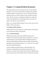
Motion vector
Visualized motion vectors. The foreground
character's rotating downward head movement is
visible, as well as the background character's
slower upward head movement.
In video compression, a motion vector is the key element in the
motion estimation process. It is used to represent a macroblock in a
picture based on the position of this macroblock (or a similar one) in
another picture, called the reference picture.
The H.264/MPEG-4 AVC standard defines motion vector as:
motion vector: A two-dimensional vector used for inter
prediction that provides an offset from the coordinates in
the decoded picture to the coordinates in a reference
picture.
[1]
[2]
References
[1] Latest working draft of H.264/MPEG-4 AVC (http:/ / www. stewe. org/ itu-recs/ h264. pdf). Retrieved on 2008-02-29.
[2] Latest working draft of H.264/MPEG-4 AVC on hhi.fraunhofer.de. (http:/ / www. hhi. fraunhofer. de/ fileadmin/ hhi/ downloads/ IP/ ip_ic_H.
264-MPEG4-AVC-Version8-FinalDraft. pdf)
Chroma subsampling
Chroma subsampling is the practice of encoding images by implementing less resolution for chroma information
than for luma information, taking advantage of the human visual system's lower acuity for color differences than for
luminance.
It is used in many video encoding schemes — both analog and digital — and also in JPEG encoding.
Rationale
In full size, this image shows the difference
between four subsampling schemes. Note how
similar the color images appear. The lower row
shows the resolution of the color information.
Because of storage and transmission limitations, there is always a
desire to reduce (or compress) the signal. Since the human visual
system is much more sensitive to variations in brightness than color, a
video system can be optimized by devoting more bandwidth to the
luma component (usually denoted Y'), than to the color difference
components Cb and Cr. In compressed images, for example, the 4:2:2
Y'CbCr scheme requires two-thirds the bandwidth of (4:4:4) R'G'B'.
This reduction results in almost no visual difference as perceived by
the viewer for photographs, although images produced digitally
containing harsh lines and saturated colors will have significant
artifacts.
[citation needed]
Chroma subsampling
6
How subsampling works
Because the human visual system is less sensitive to the position and motion of color than luminance, bandwidth can
be optimized by storing more luminance detail than color detail. At normal viewing distances, there is no perceptible
loss incurred by sampling the color detail at a lower rateWikipedia:Vagueness. In video systems, this is achieved
through the use of color difference components. The signal is divided into a luma (Y') component and two color
difference components (chroma).
In human vision there are two chromatic channels as well as a luminance channel, and in color science there are two
chromatic dimensions as well as a luminance dimension. In neither the vision nor the science is there complete
independence of the chromatic and the luminance. Luminance information can be gleaned from the chromatic
information; e.g. the chromatic value implies a certain minimum for the luminance value. But there can be no
question of color influencing luminance in the absence of a post-processing of the separate signals. In video, the
luma and chroma components are formed as a weighted sum of gamma-corrected (tristimulus) R'G'B' components
instead of linear (tristimulus) RGB components. As a result, luma must be distinguished from luminance. That there
is some "bleeding" of luminance and color information between the luma and chroma components in video, the error
being greatest for highly saturated colors and noticeable in between the magenta and green bars of a color bars test
pattern (that has chroma subsampling applied), should not be attributed to this engineering approximation being
used. Indeed similar bleeding can occur also with gamma = 1, whence the reversing of the order of operations
between gamma correction and forming the weighted sum can make no difference. The chroma can influence the
luma specifically at the pixels where the subsampling put no chroma. Interpolation may then put chroma values there
which are incompatible with the luma value there, and further post-processing of that Y'CbCr into R'G'B' for that
pixel is what ultimately produces false luminance upon display.
Original without color subsampling. 200% zoom.
Image
after color subsampling (compressed with Sony Vegas DV codec, box filtering applied.)
Sampling systems and ratios
The subsampling scheme is commonly expressed as a three part ratio J:a:b (e.g. 4:2:2), although sometimes
expressed as four parts (e.g. 4:2:2:4), that describe the number of luminance and chrominance samples in a
conceptual region that is J pixels wide, and 2 pixels high. The parts are (in their respective order):
• J: horizontal sampling reference (width of the conceptual region). Usually, 4.
• a: number of chrominance samples (Cr, Cb) in the first row of J pixels.
• b: number of (additional) chrominance samples (Cr, Cb) in the second row of J pixels.
• Alpha: horizontal factor (relative to first digit). May be omitted if alpha component is not present, and is equal to
J when present.
An explanatory image of different chroma subsampling schemes can be seen at the following link: http:/ / lea.
hamradio. si/ ~s51kq/ subsample. gif (source: "Basics of Video": http:/ / lea. hamradio. si/ ~s51kq/ V-BAS. HTM) or
in details in Chrominance Subsampling in Digital Images, by Douglas Kerr
[1]
.
Chroma subsampling
7
4:1:1 4:2:0 4:2:2 4:4:4 4:4:0
Y'CrCb
= = = = =
Y'
+ + + + +
1 2 3 4 J = 4 1 2 3 4 J = 4 1 2 3 4 J = 4 1 2 3 4 J = 4 1 2 3 4 J = 4
(Cr, Cb) 1 a = 1 1 2 a = 2 1 2 a = 2 1 2 3 4 a = 4 1 2 3 4 a = 4
1 b = 1 b = 0 1 2 b = 2 1 2 3 4 b = 4 b = 0
¼ horizontal resolution,
full vertical resolution
½ horizontal resolution,
½ vertical resolution
½ horizontal resolution,
full vertical resolution
full horizontal resolution,
full vertical resolution
full horizontal resolution,
½ vertical resolution
The mapping examples given are only theoretical and for illustration. Also note that the diagram does not indicate
any chroma filtering, which should be applied to avoid aliasing.
To calculate required bandwidth factor relative to 4:4:4 (or 4:4:4:4), one needs to sum all the factors and divide the
result by 12 (or 16, if alpha is present).
Types of subsampling
4:4:4 Y'CbCr
Each of the three Y'CbCr components have the same sample rate. This scheme is sometimes used in high-end film
scanners and cinematic postproduction. Two SDI links (connections) are normally required to carry this bandwidth:
Link A would carry a 4:2:2 signal, Link B a 0:2:2, when combined would make 4:4:4.
4:4:4 R'G'B' (no subsampling)
Note that "4:4:4" may instead be referring to R'G'B' color space, which implicitly does not have any chroma
subsampling at all. Formats such as HDCAM SR can record 4:4:4 R'G'B' over dual-link HD-SDI.
4:2:2
The two chroma components are sampled at half the sample rate of luma: the horizontal chroma resolution is halved.
This reduces the bandwidth of an uncompressed video signal by one-third with little to no visual difference.
Many high-end digital video formats and interfaces use this scheme:
•• AVC-Intra 100
• Digital Betacam
• DVCPRO50 and DVCPRO HD
•• Digital-S
• CCIR 601 / Serial Digital Interface / D1
•• ProRes (HQ, 422, LT, and Proxy)
•• XDCAM HD422
•• Canon MXF HD422
Chroma subsampling
8
4:2:1
This sampling mode is not expressible in J:a:b notation. '4:2:1' is a hangover from a previous notational scheme, and
very few software or hardware codecs use it. Cb horizontal resolution is half that of Cr (and a quarter of the
horizontal resolution of Y). This exploits the fact that human eye has less spatial sensitivity to blue/yellow than to
red/green. NTSC is similar, in using lower resolution for blue/yellow than red/green, which in turn has less
resolution than luma.
4:1:1
In 4:1:1 chroma subsampling, the horizontal color resolution is quartered, and the bandwidth is halved compared to
no chroma subsampling. Initially, 4:1:1 chroma subsampling of the DV format was not considered to be broadcast
quality and was only acceptable for low-end and consumer applications. Currently, DV-based formats (some of
which use 4:1:1 chroma subsampling) are used professionally in electronic news gathering and in playout servers.
DV has also been sporadically used in feature films and in digital cinematography.
In the NTSC system, if the luma is sampled at 13.5‚MHz, then this means that the Cr and Cb signals will each be
sampled at 3.375‚MHz, which corresponds to a maximum Nyquist bandwidth of 1.6875‚MHz, whereas traditional
"high-end broadcast analog NTSC encoder" would have a Nyquist bandwidth of 1.5‚MHz and 0.5‚MHz for the I/Q
channels. However in most equipment, especially cheap TV sets and VHS/Betamax VCR's the chroma channels
have only the 0.5‚MHz bandwidth for both Cr and Cb (or equivalently for I/Q). Thus the DV system actually
provides a superior color bandwidth compared to the best composite analog specifications for NTSC, despite having
only 1/4 of the chroma bandwidth of a "full" digital signal.
Formats that use 4:1:1 chroma subsampling include:
• DVCPRO (NTSC and PAL)
• NTSC DV and DVCAM
•• D-7
4:2:0
In 4:2:0, the horizontal sampling is doubled compared to 4:1:1, but as the Cb and Cr channels are only sampled on
each alternate line in this scheme, the vertical resolution is halved. The data rate is thus the same. This fits
reasonably well with the PAL color encoding system since this has only half the vertical chrominance resolution of
NTSC. It would also fit extremely well with the SECAM color encoding system since like that format, 4:2:0 only
stores and transmits one color channel per line (the other channel being recovered from the previous line). However,
little equipment has actually been produced that outputs a SECAM analogue video signal. In general SECAM
territories either have to use a PAL capable display or a transcoder to convert the PAL signal to SECAM for display.
Different variants of 4:2:0 chroma configurations are found in:
• All ISO/IEC MPEG and ITU-T VCEG H.26x video coding standards including H.262/MPEG-2 Part 2
implementations (although some profiles of MPEG-4 Part 2 and H.264/MPEG-4 AVC allow higher-quality
sampling schemes such as 4:4:4)
• DVD-Video and Blu-ray Disc.
• PAL DV and DVCAM
•• HDV
• AVCHD and AVC-Intra 50
•• Apple Intermediate Codec
• most common JPEG/JFIF and MJPEG implementations
•• VC-1
Cb and Cr are each subsampled at a factor of 2 both horizontally and vertically.
Chroma subsampling
9
There are three variants of 4:2:0 schemes, having different horizontal and vertical siting.
•• In MPEG-2, Cb and Cr are cosited horizontally. Cb and Cr are sited between pixels in the vertical direction (sited
interstitially).
•• In JPEG/JFIF, H.261, and MPEG-1, Cb and Cr are sited interstitially, halfway between alternate luma samples.
•• In 4:2:0 DV, Cb and Cr are co-sited in the horizontal direction. In the vertical direction, they are co-sited on
alternating lines.
Most digital video formats corresponding to PAL use 4:2:0 chroma subsampling, with the exception of DVCPRO25,
which uses 4:1:1 chroma subsampling. Both the 4:1:1 and 4:2:0 schemes halve the bandwidth compared to no
chroma subsampling.
With interlaced material, 4:2:0 chroma subsampling can result in motion artifacts if it is implemented the same way
as for progressive material. The luma samples are derived from separate time intervals while the chroma samples
would be derived from both time intervals. It is this difference that can result in motion artifacts. The MPEG-2
standard allows for an alternate interlaced sampling scheme where 4:2:0 is applied to each field (not both fields at
once). This solves the problem of motion artifacts, reduces the vertical chroma resolution by half, and can introduce
comb-like artifacts in the image.
Original. *This image shows a single field. The moving text has some motion blur applied to it.
4:2:0 progressive sampling applied to moving interlaced material. Note that the chroma leads and trails the moving
text. *This image shows a single field.
4:2:0 interlaced sampling applied to moving interlaced material. *This image shows a single field.
In the 4:2:0 interlaced scheme however, vertical resolution of the chroma is roughly halved since the chroma
samples effectively describe an area 2 samples wide by 4 samples tall instead of 2X2. As well, the spatial
displacement between both fields can result in the appearance of comb-like chroma artifacts.
Original still image.
4:2:0 progressive sampling applied to a still image. Both fields are shown.
Chroma subsampling
10
4:2:0 interlaced sampling applied to a still image. Both fields are shown.
If the interlaced material is to be de-interlaced, the comb-like chroma artifacts (from 4:2:0 interlaced sampling) can
be removed by blurring the chroma vertically.
4:1:0
This ratio is possible, and some codecs support it, but it is not widely used. This ratio uses half of the vertical and
one-fourth the horizontal color resolutions, with only one-eighth of the bandwidth of the maximum color resolutions
used. Uncompressed video in this format with 8-bit quantization uses 10 bytes for every macropixel (which is 4 x 2
pixels). It has the equivalent chrominance bandwidth of a PAL I signal decoded with a delay line decoder, and still
very much superior to NTSC.
•• Some video codecs may operate at 4:1:0.5 or 4:1:0.25 as an option, so as to allow similar to VHS quality.
3:1:1
Used by Sony in their HDCAM High Definition recorders (not HDCAM SR). In the horizontal dimension, luma is
sampled horizontally at three quarters of the full HD sampling rate- 1440 samples per row instead of 1920. Chroma
is sampled at 480 samples per row, a third of the luma sampling rate.
In the vertical dimension, both luma and chroma are sampled at the full HD sampling rate (1080 samples vertically).
Out-of-gamut colors
One of the artifacts that can occur with chroma subsampling is that out-of-gamut colors can occur upon chroma
reconstruction. Suppose the image consisted of alternating 1-pixel red and black lines and the subsampling omitted
the chroma for the black pixels. Chroma from the red pixels will be reconstructed onto the black pixels, causing the
new pixels to have positive red and negative green and blue values. As displays cannot output negative light
(negative light does not exist), these negative values will effectively be clipped and the resulting luma value will be
too high. Similar artifacts arise in the less artificial example of gradation near a fairly sharp red/black boundary.
Filtering during subsampling can also cause colors to go out of gamut.
Terminology
The term Y'UV refers to an analog encoding scheme while Y'CbCr refers to a digital encoding scheme.
[citation needed]
One difference between the two is that the scale factors on the chroma components (U, V, Cb, and Cr) are different.
However, the term YUV is often used erroneously to refer to Y'CbCr encoding. Hence, expressions like "4:2:2
YUV" always refer to 4:2:2 Y'CbCr since there simply is no such thing as 4:x:x in analog encoding (such as YUV).
In a similar vein, the term luminance and the symbol Y are often used erroneously to refer to luma, which is denoted
with the symbol Y'. Note that the luma (Y') of video engineering deviates from the luminance (Y) of color science
(as defined by CIE). Luma is formed as the weighted sum of gamma-corrected (tristimulus) RGB components.
Luminance is formed as a weighed sum of linear (tristimulus) RGB components.
In practice, the CIE symbol Y is often incorrectly used to denote luma. In 1993, SMPTE adopted Engineering
Guideline EG 28, clarifying the two terms. Note that the prime symbol ' is used to indicate gamma correction.
Similarly, the chroma/chrominance of video engineering differs from the chrominance of color science. The
chroma/chrominance of video engineering is formed from weighted tristimulus components, not linear components.
Chroma subsampling
11
In video engineering practice, the terms chroma, chrominance, and saturation are often used interchangeably to refer
to chrominance.
History
Chroma subsampling was developed in the 1950s by Alda Bedford for the development of color television by RCA,
which developed into the NTSC standard; luma-chroma separation was developed earlier, in 1938 by Georges
Valensi.
Through studies, he showed that the human eye has high resolution only for black and white, somewhat less for
"mid-range" colors like yellows and greens, and much less for colors on the end of the spectrum, reds and blues.
Using this knowledge allowed RCA to develop a system in which they discarded most of the blue signal after it
comes from the camera, keeping most of the green and only some of the red; this is chroma subsampling in the YIQ
color space, and is roughly analogous to 4:2:1 subsampling, in that it has decreasing resolution for luma,
yellow/green, and red/blue.
Effectiveness
While subsampling can easily reduce the size of an uncompressed image by 50% with minimal loss of quality, the
final effect on the size of a compressed image is considerably less.
[citation needed]
This is because image compression
algorithms also remove redundant chroma information. In fact, by applying something as rudimentary as chroma
subsampling prior to compression, information is removed from the image that could be used by the compression
algorithm to produce a higher quality result with no increase in size. For example, with wavelet compression
methods, better results are obtained by dropping the highest frequency chroma layer inside the compression
algorithm than by applying chroma subsampling prior to compression. This is because wavelet compression operates
by repeatedly using wavelets as high and low pass filters to separate frequency bands in an image, and the wavelets
do a better job than chroma subsampling does.
[citation needed]
Compatibility issues
The details of chroma subsampling implementation cause considerable confusion. Is the upper leftmost chroma value
stored, or the rightmost, or is it the average of all the chroma values? This must be exactly specified in standards and
followed by all implementors. Incorrect implementations cause the chroma of an image to be offset from the luma.
Repeated compression/decompression can cause the chroma to "travel" in one direction. Different standards may use
different versions for example of "4:2:0" with respect to how the chroma value is determined, making one version of
"4:2:0" incompatible with another version of "4:2:0".
Proper upsampling of chroma can require knowing whether the source is progressive or interlaced, information
which is often not available to the upsampler.
Chroma subsampling causes problems for film makers trying to do keying with blue or green screening. The chroma
interpolation along edges produces noticeable haloing artifacts.
Chroma subsampling
12
References
[1] http:/ / dougkerr. net/ pumpkin/ articles/ Subsampling. pdf
• Poynton, Charles. "YUV and luminance considered harmful: A plea for precise terminology in video" (http:/ /
www. poynton. com/ papers/ YUV_and_luminance_harmful. html)
•• Poynton, Charles. "Digital Video and HDTV: Algorithms and Interfaces". U.S.: Morgan Kaufmann Publishers,
2003.
• Kerr, Douglas A. "Chrominance Subsampling in Digital Images" (http:/ / dougkerr. net/ pumpkin/ articles/
Subsampling. pdf)
Article Sources and Contributors
13
Article Sources and Contributors
Motion compensation ‚Source: ‚Contributors: 3dtech, Abdkhanz, AlyM, Arnero, Atlant, Autiger, AvicAWB, Berrinam, C xong, C. A.
Russell, Cat5nap, CecilWard, Clark matt, Cogiati, Colinmanning, Conquerist, Damian Yerrick, Daniel.Cardenas, Dark Shikari, Davidhorman, Dinamisbo, Djj4, DmitriyV, Electron9, Eyreland,
Frankk74, Gary D, Gobeirne, Goodone121, Huffers, Intgr, Isnow, Kegon, Kku, Klemen Kocjancic, Lethe, Maxis ftw, Mild Bill Hiccup, MinorContributor, Mnemo, MoreNet, Mstuomel, Mudd1,
Mulligatawny, Ngarnham, Nxavar, OverlordQ, Patriarch, Patrick, Patrickdepinguin, Rade Kutil, Rcooley, Revent, Romanski, Shinglor, Spaden1, Stevenj, Stubblyhead, SudoMonas, Sumail,
TenPoundHammer, TheRoan, Tkho, Upholder, Vutrankien, Whoop whoop, 59 anonymous edits
Motion vector ‚Source: ‚Contributors: Conquistador2k6, Electron9, Fabrictramp, Klisanor, Kocio, Leofric1, MLeb, Michael Hardy,
Mudd1, Pdcook, WereSpielChequers, 5 anonymous edits
Chroma subsampling ‚Source: ‚Contributors: Abolen, Abradoks, Ahruman, AlexL1118, Algocu, AlyM, AnarchyElmo, Auiow,
Betacommand, BirdValiant, Bitoffish, Blanchardb, Brion VIBBER, Cantalamessa, ChrisGualtieri, Cmglee, CommonsDelinker, CosineKitty, Crissov, Cyrilgermond, Czarkoff, D-CinemaGuy,
Dadr, Damian Yerrick, Dcouzin, Dekart, Deville, Dicklyon, Djg2006, DmitryKo, DrVeghead, Drewcifer3000, Drilnoth, Everyking, Eyreland, Fleminra, Fogelmatrix, Fycafterpro, Gallando,
Gang65, Gareth Owen, Georgia guy, Giftlite, Gij, Glennchan, GrandDrake, Grendelkhan, Grm wnr, Heycam, Isnow, Itinerant1, Janke, Javache, Jerde, Jgro, Jhartmann, Kc2idf, Ketiltrout,
Kikawala, LOL, LightStarch, LilHelpa, Lostchicken, Mdd4696, Mikeblas, Mikus, MinorContributor, Msikma, Mugunth Kumar, Nbarth, OranL, OverlordQ, Phlake, Quadell, Quibik,
Raulsaavedraf, Ray andrew, Reaper Eternal, Richi, Schmeditator, Sergei.yakovlev, Shawnc, Smalljim, Smyth, Snafflekid, Sneakums, Stib, Stratadrake, Tagremover, Telecineguy, The undertow,
Tom Morris, Tooki, Totsugeki, Tuxick, VMS Mosaic, Vincent Liu, Wavelength, WinTakeAll, Xavier Giró, Xu9780, Yuriybrisk, Zigger, 128 anonymous edits
Image Sources, Licenses and Contributors
14
Image Sources, Licenses and Contributors
Image:Elephantsdream_vectorstill04_crop.png ‚Source: ‚License: Creative Commons Attribution 3.0
‚Contributors: Christian Mertes
File:Motion compensation example-original.jpg ‚Source: ‚License: Creative Commons Attribution
2.5 ‚Contributors: (c) copyright 2006, Blender Foundation / Netherlands Media Art Institute / www.elephantsdream.org
File:Motion compensation example-difference.jpg ‚Source: ‚License: Creative Commons
Attribution 2.5 ‚Contributors: (c) copyright 2006, Blender Foundation / Netherlands Media Art Institute / www.elephantsdream.org
File:Motion compensation example-compensated difference.jpg ‚Source: ‚License:
Creative Commons Attribution 2.5 ‚Contributors: (c) copyright 2006, Blender Foundation / Netherlands Media Art Institute / www.elephantsdream.org
File:Sintel Motion Vectors.png ‚Source: ‚License: Creative Commons Attribution 3.0 ‚Contributors: Mudd1
File:Colorcomp.jpg ‚Source: ‚License: Creative Commons Attribution-Sharealike 3.0 ‚Contributors: Janke
File:Color-bars-original.gif ‚Source: ‚License: Public Domain ‚Contributors: Glenn Chan
File:Color-bars-vegas-dv.gif ‚Source: ‚License: Public Domain ‚Contributors: Glenn Chan
File:444-original-single-field.png ‚Source: ‚License: GNU Free Documentation License ‚Contributors: Glennchan at
en.wikipedia
Image:420-progressive-single-fiel.png ‚Source: ‚License: Public Domain ‚Contributors: Glennchan at en.wikipedia
File:420-interlaced-single-field.png ‚Source: ‚License: GNU Free Documentation License ‚Contributors: Glenn
Chan
File:420-original444.png ‚Source: ‚License: Public Domain ‚Contributors: Glenn Chan
File:420-progressive-still.png ‚Source: ‚License: Public Domain ‚Contributors: Glenn Chan
File:420-interlaced-still.png ‚Source: ‚License: Public Domain ‚Contributors: Glenn Chan
License
15
License
Creative Commons Attribution-Share Alike 3.0
//creativecommons.org/licenses/by-sa/3.0/