neri, caramella, bartolozzi - image processing in radiology - current applications (springer, 2008)
Bạn đang xem bản rút gọn của tài liệu. Xem và tải ngay bản đầy đủ của tài liệu tại đây (16.73 MB, 432 trang )
Contents
I
MEDICAL RADIOLOGY
Diagnostic Imaging
Editors:
A. L. Baert, Leuven
M. Knauth, Göttingen
K. Sartor, Heidelberg
Contents
III
E. Neri · D. Caramella · C. Bartolozzi (Eds.)
Image Processing
in Radiology
Current Applications
With Contributions by
A. J. Aschoff · E. Balogh · C. Bartolozzi · A. Bardine · V. Battaglia · C. R. Becker
R. Beichel · W. Birkfellner · A. Blum-Moyse · P. Boraschi · A. Bornik · E. Bozzi · C. Capelli
D. Caramella · C. Cecchi · F. Cerri · K. Cleary · A. Cotton · L. Crocetti · C. N. De Cecco
C. Della Pina · A. H. de Vries · F. Donati · R. Ferrari · G. Fichtinger · G. Galatola
T. M. Gallo · S. J. Golding · F. Iafrate · A. Jackson · N. W. John · S. Karampekios
J. Kettenbach · G. Kronreif · A. Laghi · L. Landini · C. Laudi · R. Lencioni · F. Lindbichler
M. Macari · P. Macheshi · S. Mazeo · B. Meyer · A. Melzer · E. Neri · L. Nyúl · K. Palágyi
V. Panebianco · P. Paolantonio · N. Papanikolaou · N. Popovic · V. Positano · D. Regge
B. Reitinger · M. Rieger · P. Rogalla · A. Ruppert · S. Salemi · M. F. Santarelli · B. Sauer
I. W. O. Serli · M. Sonka · E. Sorantin · S. M. Stivaros · D. Stoianovici · J. Stoker · V. Tartaglia
B. M. ter Haar Romeny · N. A. Thacker · F. Turini · P. Vagli · A. Vilanova i Bartrolí
T. W. Vomweg · F. M. Vos · S. R. Watt-Smith · G. Werkgartner · H. Yoshida
Foreword by
A. L. Baert
With 297 Figures in 544 Separate Illustrations, 224 in Color and 44 Tables
123
IV
Contents
Emanuele Neri, MD
Diagnostic and Interventional Radiology
Department of Oncology, Transplants,
and Advanced Technologies in Medicine
University of Pisa
Via Roma 67
56100 Pisa
Italy
Davide Caramella, MD
Professor, Diagnostic and Interventional Radiology
Department of Oncology, Transplants,
and Advanced Technologies in Medicine
University of Pisa
Via Roma 67
56100 Pisa
Italy
Medical Radiology · Diagnostic Imaging and Radiation Oncology
Series Editors:
A. L. Baert · L. W. Brady · H P. Heilmann · M. Knauth · M. Molls · C. Nieder · K. Sartor
Continuation of Handbuch der medizinischen Radiologie
Encyclopedia of Medical Radiology
Library of Congress Control Number: 2006936011
ISBN 978-3-540-25915-2 Springer Berlin Heidelberg New York
This work is subject to copyright. All rights are reserved, whether the whole or part of the material is concerned,
specifi cally the rights of translation, reprinting, reuse of illustrations, recitations, broadcasting, reproduction on
microfi lm or in any other way, and storage in data banks. Duplication of this publication or parts thereof is permit-
ted only under the provisions of the German Copyright Law of September 9, 1965, in its current version, and permis-
sion for use must always be obtained from Springer-Verlag. Violations are liable for prosecution under the German
Copyright Law.
Springer is part of Springer Science+Business Media
http//www.springer.com
© Springer-Verlag Berlin Heidelberg 2008
Printed in Germany
The use of general descriptive names, trademarks, etc. in this publication does not imply, even in the absence of a
specifi c statement, that such names are exempt from the relevant protective laws and regulations and therefore free
for general use.
Product liability: The publishers cannot guarantee the accuracy of any information about dosage and application
contained in this book. In every case the user must check such information by consulting the relevant literature.
Medical Editor: Dr. Ute Heilmann, Heidelberg
Desk Editor: Ursula N. Davis, Heidelberg
Production Editor: Kurt Teichmann, Mauer
Cover-Design and Typesetting: Verlagsservice Teichmann, Mauer
Printed on acid-free paper – 21/3180xq – 5 4 3 2 1 0
Carlo Bartolozzi, MD
Professor, Division of Diagnostic
and Interventional Radiology
Department of Oncology, Transplants,
and New Technologies in Medicine
University of Pisa
Via Roma 67
56100 Pisa
Italy
Contents
V
Foreword
Computer applications for image processing in radiological imaging have matured
over the past decade and are now considered an indispensable tool for extracting maxi-
mal information from the enormous amount of data obtained with the new cross-sec-
tional techniques such as ultrasound, computed tomography and magnetic resonance
imaging. Indeed, the exquisite display of anatomy and pathology in all possible planes
provided by these methods offers new and specifi c diagnostic information which will
contribute to a better therapeutic management of the patient.
This volume not only covers very comprehensively the fundamental technical aspects
of modern imaging processing, including the latest advances in this rapidly evolving
fi eld, but it also deals systematically and in depth with the numerous clinical applica-
tions in those specifi c body areas where these methods can be successfully applied.
Special chapters are devoted to 3D image fusion and to image-guided robotic surgery.
The well readable text is completed by numerous superb illustrations.
The editors, all from the department of diagnostic and interventional radiology of
the University of Pisa, are internationally well known experts in the fi eld and all share
longstanding dedication and interest in radiological image processing, as demonstrated
by their innovative research and publications. Other leading international experts have
contributed outstanding individual chapters based on their specifi c expertise.
I would like to thank and congratulate most sincerely the editors and authors for
their superb efforts which have resulted in this much needed and excellent book which
will be of great assistance to all radiologists in their daily clinical work, as well as to
surgeons and other medical specialists interested in enlarging their knowledge in this
wonderful world of radiological computer processing.
I am confi dent that it will meet with the same success among readers as the previous
volumes published in this series.
Leuven Albert L. Baert
Contents
VII
Preface
Two and three-dimensional image processing is an essential and integral part of the diag-
nostic workfl ow in the Radiology Department nowadays, signifi cantly improving the qual-
ity of diagnosis and at the same time increasing reporting times. Thus, a precise knowledge
of the technical aspects and clinical impact of image processing is mandatory for radiolo-
gists.
In this book, a group of well recognized experts in the fi eld have sought to provide the
radiologist with the information essential to optimizing the use of image processing tools
in clinical workfl ow.
The initial section of the book is dedicated to the technical aspects of image processing,
from image acquisition to image processing in the 2D and 3D domain. A larger part of the
book is dedicated to clinical applications, where specifi c topics of Radiology subspecialties
are comprehensively covered. A special topic section completes the book, highlighting new
and advanced fi elds of research, such as computer-aided diagnosis and robotics.
We hope to have achieved our aim of providing our colleagues with a useful reference
tool in their daily practice.
We would like to express our thanks to all the authors for their outstanding contribute.
We are also very grateful to Prof. Albert Baert for his valuable support in this project.
Pisa Emanuele Neri
Davide Caramella
Carlo Bartolozzi
Contents
IX
Technical Basis of Image Processing
1 US Image Acquisition
Elena Bozzi, Laura Crocetti, and Riccardo Lencioni . . . . . . . . . . . . . . 3
2 3D MRI Acquisition: Technique
Nickolas Papanikolaou and Spyros Karampekios. . . . . . . . . . . . . . . . . 15
3 MDCT Image Acquisition to Enable Optimal 3D Data Evaluation
Michael Macari . . . . . . . . . . . . . . . . . . . . . . . . . . . . . . . . . . . . . . 27
4 Segmentation of Radiological Images
Nigel W. John . . . . . . . . . . . . . . . . . . . . . . . . . . . . . . . . . . . . . . . . 45
5 Elaboration of the Images in the Spatial Domain. 2D Graphics
Paolo Marcheschi . . . . . . . . . . . . . . . . . . . . . . . . . . . . . . . . . . . . . 55
6 3D Medical Image Processing
Luigi Landini, Vincenzo Positano, and Maria Filomena Santarelli . . . . 67
7 Virtual Endoscopy
Paola Vagli, Emanuele Neri, Francesca Turini, Francesca Cerri,
Claudia Cecchi, Alex Bardine, and Davide Caramella. . . . . . . . . . . . . 87
8 3D Image Fusion
Alan Jackson, Neil A. Thacker, and Stavros M. Stivaros . . . . . . . . . . . . 101
9 Image Processing on Diagnostic Workstations
Bart M. ter Haar Romeny. . . . . . . . . . . . . . . . . . . . . . . . . . . . . . . . 123
Image Processing: Clinical Applications
10 Temporal Bone
Paola Vagli, Francesca Turini, Francesca Cerri, and Emanuele Neri . . . 137
11 Virtual Endoscopy of the Paranasal Sinuses
Joachim Kettenbach, Wolfgang Birkfellner, and Patrik Rogalla . . . . . 151
12 Dental and Maxillofacial Applications
Stephen J. Golding and Stephen R. Watt-Smith . . . . . . . . . . . . . . . . . . 173
13 Virtual Laryngoscopy
Joachim Kettenbach, Wolfgang Birkfellner, Erich Sorantin,
and Andrik J. Aschoff . . . . . . . . . . . . . . . . . . . . . . . . . . . . . . . . . . 183
14 Thorax
Henning Meyer and Patrik Rogalla . . . . . . . . . . . . . . . . . . . . . . . . . 199
15 Cardiovascular Applications
Christoph R. Becker . . . . . . . . . . . . . . . . . . . . . . . . . . . . . . . . . . . 209
Contents
X
Contents
16 From the Esophagus to the Small Bowel
Franco Iafrate, Pasquale Paolantonio, Carlo Nicola De Cecco,
Riccardo Ferrari, Valeria Panebianco, and Andrea Laghi . . . . . . . . . . 221
17 CT and MR Colonography
Daniele Regge, Teresa Maria Gallo, Cristiana Laudi,
Giovanni Galatola, and Vincenzo Tartaglia . . . . . . . . . . . . . . . . . . . 239
18 Techniques of Virtual Dissection of the Colon Based on Spiral CT Data
Erich Sorantin, Emese Balogh, Anna Vilanova i Bartrolí,
Kálmán Palágyi, László G. Nyúl, Franz Lindbichler,
and Andrea Ruppert . . . . . . . . . . . . . . . . . . . . . . . . . . . . . . . . . . . 257
19 Unfolded Cube Projection of the Colon
Ayso H. de Vries, Frans M. Vos, Iwo W. O. Serlie, and Jaap Stoker . . . . . 269
20 Liver
Laura Crocetti, Elena Bozzi, Clotilde Della Pina, Riccardo Lencioni,
and Carlo Bartolozzi . . . . . . . . . . . . . . . . . . . . . . . . . . . . . . . . . . 277
21 Pancreas
Salvatore Mazzeo, Valentina Battaglia, Carla Cappelli. . . . . . . . . . . 293
22 Biliary Tract
Piero Boraschi and Francescamaria Donati . . . . . . . . . . . . . . . . . . . 303
23 Urinary Tract
Piero Boraschi, Francescamaria Donati, and Simonetta Salemi . . . . . . 317
24 Musculoskeletal System
Anne Cotton, Benoît Sauer, and Alain Blum-Moyse . . . . . . . . . . . . . . 329
Special Topics
25 Clinical Applications of 3D Imaging in Emergencies
Michael Rieger. . . . . . . . . . . . . . . . . . . . . . . . . . . . . . . . . . . . . . . 345
26 Computer Aided Diagnosis: Clinical Applications in the Breast
Toni W. Vomweg . . . . . . . . . . . . . . . . . . . . . . . . . . . . . . . . . . . . . . 355
27 Computer Aided Diagnosis: Clinical Applications in CT Colonography
Hiroyuki Yoshida and Abraham H. Dachman . . . . . . . . . . . . . . . . . . . 375
28 Ultrasound-, CT-and MR-Guided Robot-Assisted Interventions
Joachim Kettenbach, Gernot Kronreif, Andreas Melzer,
Gabor Fichtinger, Dan Stoianovici, and Kevin Cleary . . . . . . . . . . . . . 393
29 Virtual Liver Surgery Planning
Erich Sorantin, Georg Werkgartner, Reinhard Beichel,
Alexander Bornik, Bernhard Reitinger, Nikolaus Popovic,
and Milan Sonka . . . . . . . . . . . . . . . . . . . . . . . . . . . . . . . . . . . . . 411
List of Acronyms . . . . . . . . . . . . . . . . . . . . . . . . . . . . . . . . . . . . . . . . . 419
Subject Index . . . . . . . . . . . . . . . . . . . . . . . . . . . . . . . . . . . . . . . . . . . 421
List of Contributors . . . . . . . . . . . . . . . . . . . . . . . . . . . . . . . . . . . . . . . 429
US Image Acquisition
1
Technical Basis of Image Processing
US Image Acquisition
3
E. Bozzi, MD
Division of Diagnostic and Interventional Radiology, Depart-
ment of Oncology, Transplants and New Technologies in
Medicine, University of Pisa, Via Roma 67, 56125 Pisa, Italy
L. Crocetti, MD
Assistant Professor, Division of Diagnostic and Interven-
tional Radiology, Department of Oncology, Transplants
and New Technologies in Medicine, University of Pisa, Via
Roma 67, 56125 Pisa, Italy
R. Lencioni, MD
Associate Professor, Division of Diagnostic and Interven-
tional Radiology, Department of Oncology, Transplants
and New Technologies in Medicine, University of Pisa, Via
Roma 67, 56125 Pisa, Italy
US Image Acquisition 1
Elena Bozzi, Laura Crocetti, and Riccardo Lencioni
1.1
Introduction
Three-dimensional (3D) ultrasonography, even if
recently gaining large popularity, is a relatively new
tool compared with 3D reconstructions obtained by
CT and MR. Ultrasonography offers unique qualities
including real-time imaging, physiologic measure-
ments, use of non-ionizing radiations and invasive-
ness. Sonographic image quality has benefi ted from
increasingly sophisticated computer technology: to
date several systems, able to generate 3D ultrasound
images, have been introduced.
Volume sonographic imaging has sparked inter-
est in the academic community since the 1961. At
that time Baum and Greenwood (1961) obtained
serial parallel ultrasound images of the human
orbit and created a 3D display by stacking sequen-
tial photographic plates with the ultrasound images.
During the early 1970s also the commercial indus-
try’s interest for 3D ultrasound imaging grew up: in
1974 the Kretztechnik group, in order to achieve 3D
images, developed a cylindrical-shaped transducer
incorporating 25 elements mounted on a drum.
This equipment performed a volume scan consist-
ing of 25 parallel slices. The next step consisted of
a more convenient end-fi re transducer producing
a fan scan. However, at that time the display and
store technology was not suitable for 3D ultrasound
imaging. In 1989 in Paris at the French Congress of
Radiology, Kretztechnik presented the fi rst com-
mercially available ultrasound system featuring
the 3D Voluson technique. It is only in the last few
years that computer technology and visualization
techniques have progressed suffi ciently to make 3D
ultrasound viable. Nowadays, 3D ultrasound imag-
ing methods allow to present, in a few seconds, the
entire volume in a single image ( Brandal et al.
1999). The success of 3D ultrasound will depend on
providing performance that equals or exceeds that
of two-dimensional (2D) ultrasonography, includ-
ing real time capability and interactivity. In addi-
CONTENTS
1.1 Introduction 3
1.2 Data Acquisition 4
1.2.1 Mechanical Scanning Systems 4
1.2.2 Tracked Freehand Systems 5
1.2.3 Untracked Freehand Systems 6
1.2.4 2D Transducer Arrays 6
1.3 Data Processing and Reconstruction 7
1.3.1 Voxel-Based Methods 7
1.3.2 Pixel-Based Methods 7
1.3.3 Function-Based Methods 7
1.4 Data Visualization 8
1.4.1 Surface Rendering 8
1.4.2 Multiplanar Reconstruction 8
1.4.3 Volume Rendering 9
1.5 Image Fusion 9
References 12
4
E. Bozzi, L. Crocetti, and R. Lencioni
tion, three-dimensional ultrasound is already being
introduced alone or together with preoperational
images for guidance of surgical applications.
US is a widely used tool for imaging guided pro-
cedures in the abdomen, especially in the liver.
Its well-known advantages can be combined with
those of computed tomography (CT) or magnetic
resonance (MR) images by means of fusion imaging
processes. Image fusion, the process of aligning and
superimposing images obtained using two different
imaging modalities, is in fact a rapidly evolving fi eld
of interest.
In this chapter, we review the various approaches
that investigators have pursued in the development
of 3D ultrasound imaging systems, with empha-
sis on the steps of the process of making 3D sono-
graphic images. Moreover, an overview on US-CT/
MR fusion imaging will be included.
1.2
Data Acquisition
Various techniques have been described until now
for acquiring a sequence of sonograms and recon-
structing them into a fi nal 3D result. Acquiring the
sequence is the critical step in the process for pri-
marily two reasons. First, because the sequence of
acquired tomographic images will be assembled into
a 3D image, the acquisition geometry must be know
exactly to avoid distortions, and the images must be
acquired rapidly to avoid patient motion. Second,
the mechanism that manipulates the transducer or
localizes its position in the space must not inter-
fere to the regular performance of the sonographic
examination. In meeting these requirements, vari-
ous solutions have been proposed. At present the
main types of 3D data acquisition systems are:
(1) mechanical scanning systems, (2) tracked
free-
hand systems, and (3) untracked freehand systems,
and (4) 2D transducer arrays.
1.2.1
Mechanical Scanning Systems
Mechanical scanning systems are based on commer-
cially available linear or annular transducer array
mounted on a mechanical assembly that allows pre-
cise movement of the transducer by a motor under
computer control. At present, two different types of
mechanical assemblies have been developed: exter-
nal transducer fi xation drive devices and, more
recently, integrated volume transducers.
External transducer fi xation drive devices rep-
resent the fi rst implementation of mechanical
scanning systems. In this approach the transducer
is mounted on a special external device (mechani-
cal arm) that holds the transducer fi rmly, offering
precise movement during scanning. The device is
then held in a fi xed position, and a motor drive
system on the device moves the transducer in a
controlled and well-defi ned fashion to sweep out
a volume. This system provides a high accuracy
in locating the position of the transducer relative
to the scanned planes. In the past it has been used
for vascular (Downey and Fenster 1995a), pros-
tate (Downey and Fenster 1995b) and obstet-
ric (Steiner et al. 1994) imaging. Because of the
constraints imposed by a rigid mechanical device
that can result in being cumbersome for the opera-
tor and may interfere with the usual sonographic
examination, to date these external devices are not
in clinical use. In order to overcome these limita-
tions, integrated volume transducers have been
introduced.
The integrated volume transducer consisted of
a conventional annular array transducer mounted
on a hand-held assembly that allows the transla-
tion or rotation of the transducer by a motor drive
computer system. Integrated volume transducers
acquire a volume as a series of slices at slightly dif-
ferent orientations. After each slice the transducer
plane is moved, by the stepping motor, to the next
location. By this, the relative angle between slices is
exactly known, eliminating distortion in the resul-
tant scan. Integrated volume transducers tend to
be relatively larger than standard transducers, but
they eliminate most of the issues related to exter-
nal position sensors with respect to calibration and
accuracy. As a result the sonographer can use the
transducer in the same manner as with conven-
tional 2D ultrasonography systems by avoiding only
immobilizing the probe during the image acquisi-
tion. It will require only a few seconds for obstetric
studies, and a longer time, approximately 1 min,
for cardiac-gated studies. Volumes can be acquired
and reconstructed rapidly without registration
artifacts. Such systems have a relatively small fi eld
of view that, although not posing problems for
imaging small structures, may represent a signifi -
cant limitation for large ones. Integrated volume
US Image Acquisition
5
transducers have been produced for both transab-
dominal and intra-cavitary probes. This approach
has been described for several applications: abdo-
men (Hamper et al. 1994), prostate (Hamper et al.
1999; Elliot et al. 1996; Tong et al. 1996), heart
(De Castro et al. 1998) and obstetric (Johnson et
al. 2000; Nelson et al. 1996). A particular applica-
tion of this approach is represented by the use of
a motorized rotating transducer mounted on the
end of a catheter and introduced into the vascula-
ture for intravascular imaging (Thrush et al. 1997;
Klein et al. 1992). Withdrawal of the catheter and
transducer through a vessel allows collection of a
series of two dimensional images for forming a 3D
volume.
The different types of mechanical assemblies
used to produce 3D images can be divided into three
basic types of motion: linear, tilting, and rotation
(Fenster and Downey 2000).
The linear scanning requires that the transducer
is moved by the stepping motor in a linear fashion
along the surface of the patient’s skin so that the
2D images obtained are parallel to each other. The
2D images are acquired at a regular spatial interval
that is adjusted to ensure appropriate sampling of
the anatomy. Because the 2D images are parallel and
the spatial sampling interval is predetermined, the
majority of the parameters required for the recon-
struction can be precomputed, and the reconstruc-
tion time can be shortened. With this approach,
a volume image can be obtained immediately after
performance of a linear scan.
With tilt scanning the transducer is titled about
its face, and images are digitized at a predeter-
mined angular interval. The main advantage of this
approach is that the scanning device is usually quite
small, which allows easy handheld manipulations.
On the contrary, the major problem related to the use
of the tilt scanning approach is that the 2D images
are acquired in a fanlike geometry; as a consequence
the space between them increases and the resolution
decreases with increasing depth.
In rotational scanning the transducer is rotated
around an axis that is perpendicular to the trans-
ducer array. The 3D image data are then acquired by
collecting a series of 2D B mode images as the probe
is rotated at constant speed. As a result, the sampling
distance increases and the resolution decreases as
distance from the rotational axis increases. In addi-
tion, the digitized images intersect along the rota-
tional axis, so that any motion creates artifacts at
the center of the 3D image.
1.2.2
Tracked Freehand Systems
The freehand approach is very attractive: the trans-
ducer can be moved freely and without any restric-
tion introduced by mechanics. The examination is
performed in the same way as a standard ultrasound
study. With tracked freehand systems,
the operator
holds an assembly composed of the transducer and
a position-sensor device and manipulates it over the
anatomic area being
evaluated. During the acquisi-
tion of 2D images the tracking device attached to the
probe monitors the spatial position and orientation
of the ultrasound transducer. The tracking device
has a limited size and weight and does not infl u-
ence the movement of the transducer, the freedom
or the usual working procedure of the physician.
This system provides fl exibility in selecting the best
image plane sampling of the tissue volume from
which data are acquired. In addition, it eliminates
the need for more complex, dedicated 3D probes,
which contain a mechanism to move the transducer
through a pre-set fi eld of acquisition. The principal
types of tracking freehand systems are: acoustic
tracking, optical tracking and magnetic fi eld track-
ing.
Acoustic tracking makes use of sound emitters
mounted on the transducer and small microphones
for sound detection. The microphones must be posi-
tioned in different locations above the patient and
must be suffi ciently near the emitters to be able to
detect the sound pulse. As the operator moves the
probe, the sound emitters are energized in rapid
sequence, producing sound waves that are detected
by the microphones. The time of fl y of the sound
impulse from each emitter to each microphone is
measured and corrected for environmental condi-
tions, and then used to calculate the position of the
transducer and the ultrasound image in a coordinate
system defi ned by the microphone array. The trig-
ger signal that is recorded by the ultrasound system
allows coordination of the imaging and positional
data. As a consequence, by activating the sound-
emitting devices while the probe is moving freely,
the position and orientation of the transducer can be
continuously monitored, and real time acquisition
of images and positional data are obtained (Ofi li
and Navin 1994; King et al. 1990). A disadvantage
of the acoustic system is the requirement of a direct
line of sight between the sensing equipment (micro-
phones) and the ultrasound probe. The general idea
with optical tracking is to use multiple cameras with
6
E. Bozzi, L. Crocetti, and R. Lencioni
markers distributed on a rigid structure, where the
geometry is specifi ed beforehand. Up to three mark-
ers are necessary to determine the position and ori-
entation of the rigid body in space. Additional mark-
ers allow a better camera visibility of the tracked
object and improve the measurement accuracy. In
addition, both the visibility of the tracked object
and the accuracy of its 3D position and orientation
are highly dependent on the position of the markers
(West and Maurer 2004; Lindeseth et al. 2003;
Treece et al. 2003).
The magnetic fi eld tracking system, on the con-
trary, does not impose any restriction on transducer
placement during scanning: magnetic tracking per-
mits free transducer movement, allowing acquisi-
tion of arbitrarily oriented 2D images from one or
more acoustic windows.
Magnetic fi eld tracking is a relatively new tracked
freehand technique that makes use of magnetic
localizers to measure the transducer’s position and
angle in the space. At present it is considered the
most successful tracked freehand technique. The
system includes a magnetic fi eld generator (trans-
mitter), a miniature magnetic sensor (receiver) and
a system control unit.
The receiver is small and mounted directly on the
ultrasound scan head. Its size does not interfere with
standard clinical ultrasound scanning methods.
The transmitter, which is usually mounted on the
examining table, emits three orthogonal magnetic
fi elds. The control unit measures and compares the
relative strengths of all three fi elds at the receiver.
These measurements are used to compute the posi-
tion and orientation of the receiver relative to the
transmitter.
To achieve accurate 3D reconstruction,
elec-
tromagnetic interference must be minimized, the
transmitter
must be close to the receiver, and there
should be no ferrous
or highly conductive metals in
the vicinity (Downey et al. 2000; Kelly et al. 1994).
Magnetic fi eld tracking systems can be used with
standard and endocavitary transducers. These sys-
tems have been used successfully for fetal (Kelly et
al. 1994; Pretorius and Nelson 1994) and vascular
(Hodges et al. 1994) 3D imaging. Recently, there has
been some development with a miniature magnetic
position sensor suitable for use with intra-vascular
transducers.
Locating US images within a tracked coordi-
nate system opens up a new world of possibilities:
the images can be registered to a patient and to
images from other modalities (Brendel et al. 2002;
Comeau et al. 2000; Dey et al. 2002; Lindeseth et
al. 2003).
All the tracking devices used for freehand sys-
tems work in a similar manner: the device tracks
the position and orientation (pose) of the sensor on
the probe, not the US image plane itself. So, an addi-
tional step must be added to compute the transfor-
mation (rotation, translation and scaling) between
the origin of the sensor mounted on the probe and
the image plane itself (Mercier et al. 2005; Hsu et
al. 2006; Gee et al. 2005).
1.2.3
Untracked Freehand Systems
The sensorless techniques attempt to estimate the
3D position and orientation of a probe in space.
Pennec et al. (2003), for example, proposed a system
where a time sequence of 3D US volumes is regis-
tered to play the role of a tracking system. Sensor-
less tracking can be done by analyzing the speckle
in the US images using decorrelation (Tut hil l et
al. 1998) or linear regression (Prager et al. 2003).
This approach does not require any kinds of devices
added to the probe. The operator has to move the
transducer with a uniform and steady motion, in a
constant linear or angular velocity. As a result the
2D images are acquired at a regular spatial inter-
val that is adjusted to ensure appropriate sampling
of the anatomy. However, Li et al. (2002) found
that it was impossible to accomplish real freehand
scanning using only speckle correlation analysis.
Although this approach can result in being very
attractive for the user, image quality is extremely
variable, depending on the regularity of the trans-
ducer’s movement. Moreover, geometric measure-
ments (distance, volume, area) may be inaccurate.
These drawbacks make the tool useless, or in any
case unsuitable for accurate clinical applications.
1.2.4
2D Transducer Arrays
This system represents the ultimate approach to 3D
sonographic acquisition. 2D arrays are matrix with
a large number of elements arranged in rows and
columns that are able, in principle, to have unre-
stricted scanning in 3D. A volumetric image is pro-
duced without moving the transducer: such an array
generates pyramidal or conical ultrasound pulse
US Image Acquisition
7
and processes the echoes to obtain 3D information
in real time. These probes are relatively large and
expensive in comparison with 2D probes, and their
image resolution is not as good as their 2D counter-
parts. Although the ultimate expectation is that 2D
transducer arrays will replace integrated mechani-
cal scanning transducers or other position-sensing
transducers, they are still in the research phase.
Investigators have described several 2D arrays sys-
tems (Tu rnbu ll and Foster 1992; Tur nbul l et
al. 1992); the one developed at Duke University for
real time 3D echocardiography is the most advanced
and has been used for clinical imaging (Light et
al. 1998; Smith et al. 1992; Von Ramm and Smith
1990). At present the major problem related to the
use of 2D transducer arrays consists of the com-
plexity of the system, which requires sophisticated
software and huge computer capabilities. In order to
reduce system cost and complexity, sparse 2D arrays
have been developed (Davidsen and Smith 1997;
Davidsen et al. 1994). Moreover, 2D array transduc-
ers are relatively small, and, as a result, their fi eld of
view also is relatively small: it may be a limitation
for large organ imaging (Nelson and Pretorius
1998). Other 3D probes can be either mechanically
or electronically steered within the probe housing.
An annular array producing a thin US beam can
be accurately controlled by an internal mechanical
motor in 2D to obtain a 3D volume with high reso-
lution. 2D probes can also be electronically steered
within the image plane to increase the fi eld of view
(FOV), as in Rohling et al. (2003).
1.3
Data Processing and Reconstruction
The 3D reconstruction process involves the genera-
tion of a 3D image from a digitized set of 2D images.
The 3D reconstruction and processing architecture
for 3D ultrasound is critical since it must take
advantage of frequent processor, accelerator, and
software upgrades to keep up with rapidly chang-
ing computer technology.
Three different groups of reconstruction algo-
rithms have been used. These groups have been dif-
ferentiated on the basis of implementation in voxel-
based methods (VBM), pixel-based methods (PBM)
and function-based methods (FBM) by Solberg et
al. (2007).
1.3.1
Voxel-Based Methods
The voxel-based volume model represents the most
common approach to 3D reconstruction techniques.
With this method a volume is generated by plac-
ing each 2D image at the proper location in the 3D
volume. In the different algorithms, one or several
pixels may contribute to the value of each voxel.
This approach preserves all the original informa-
tion during 3D reconstruction: it allows reviewing
repeatedly the 3D image by a variety of rendering
techniques. Using a voxel-based volume model, the
operator can scan through the data and then chooses
the most suitable rendering technique. Moreover,
this approach allows the use of segmentation and
classifi cation algorithms to measure volume and
segment boundaries or the performance of vari-
ous volume-based rendering operations. The major
limitation of the voxel-based volume model is that it
generates very large data fi les, requiring amounts of
computer memory and making the 3D reconstruc-
tion process slower.
1.3.2
Pixel-Based Methods
Pixel-based methods traverse each pixel in the input
images and assign the pixel value to one or several
voxels. A PBM may consist of two steps: a distri-
bution step (DS) and a hole-fi lling step (HFS). In
the DS, the input pixels are traversed and the pixel
value applied to one or several voxels, often stored
together with a weight value. In the HFS, the voxels
are traversed and empty voxels are being fi lled. Most
hole-fi lling methods have a limit on how far from
away from known values the holes are fi lled, so if
the input images are too far apart or the hole-fi lling
limits are too small, there will still be holes in the
constructed volume.
1.3.3
Function-Based Methods
Function-based methods choose a particular func-
tion (like a polynomial) and determine coeffi cients
to make one or more functions pass through the
input pixels. Afterwards, the functions are used to
create a regular voxel array by evaluating the func-
tions at regular intervals.
8
E. Bozzi, L. Crocetti, and R. Lencioni
1.4
Data Visualization
Once the volume has been created, it can be viewed
interactively by the use of any 3D visualization and
rendering software. Visualization of 3D data plays
an important part in the development and use of
3D ultrasound, with three predominant approaches
being utilized thus far: surface rendering, multi-
planar reconstructions, and volume rendering
(Fig. 1.1).
1.4.1
Surface Rendering
At present surface rendering is the most common
3D display technique. In surface rendering the sur-
faces of structures or organs are portrayed in the
rendition. The surface can be extracted manually
or automatically. Manual segmentation methods
give the most accurate surface, but are a lengthy
and laborious task for the operator. Unfortunately,
to date, automatic segmentation methods, requir-
ing simple user assistance, cannot be guaranteed to
a lw ay s w ork c or rec t ly i n la rge appl ic at ions . Wit h t h is
approach the boundaries are represented by a wire
frame or mesh, the surface is texture mapped with
an appropriate color and texture to represent the
anatomical structure (Fenster and Downey 2000;
Downey et al. 2000). Echocardiographic (Wa ng et
al. 1994; Rankin et al. 1993) and fetal (Lee et al.
1995; Kelly 1994; Nelson and Pretorius 1992) 3D
studies represent the major clinical applications of
this rendering technique.
1.4.2
Multiplanar Reconstruction
At present two different multiplanar reconstruction
techniques have been developed: section display and
texture mapping.
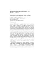
Fig. 1.1a–c. Surface rendering for fetal imaging, showing a
30-week-old fetus (a), volume-rendering methods for liver
imaging (b) and multiplanar reconstruction of a focal nod-
ular hyperplasia in the liver (c) (courtesy of ESAOTE)
a c
b
US Image Acquisition
9
Section display allows visualization of multiple
sections of the acquired volume scan along three
orthogonal planes: acquisition plane, transverse or
sagittal reconstructed plane, and C-plane (parallel
to the transducer surface). Computer-user inter-
face tools allow the operator to rotate and reposi-
tion these planes so that the entire volume of data
can be examined. Because this technique is easy
to implement and allows short 3D reconstruction
times, it has been largely used in clinical applica-
tions (Hamper et al. 1994).
The second technique, called texture mapping,
displays the 3D image as a polyhedron with the
appropriate anatomy texture mapped on each face.
The reconstructed structure can be viewed by slic-
ing into the volume, interactively, to form a cross-
sectional image of the volume acquired in any orien-
tation. As a result, this rendering approach provides
a good means for visualizing spatial relationships
for the entire volume in a readily comprehended
manner (Tong et al. 1996; Fishman et al. 1991).
1.4.3
Volume Rendering
Volume-rendering methods map voxels directly
onto the screen without using geometric primitives.
They require that the entire data set be sampled
each time an image is rendered or re-rendered.
Volume rendering algorithms are attractive tools
for displaying an image that synthesizes all the
data contained in the numerical volume. The most
popular volume visualization algorithm for the
production of high-quality images is ray-casting.
With the ray-casting approach a 2D array of rays
is projected through the 3D image. Shading and
transparency voxel values along each ray are then
examined, multiplied by factors, and summed to
achieve the desired rendering result. A wide spec-
trum of visual effects can be generated depend-
ing on how the algorithm interacts with each
voxel encountered by a particular ray. Maximum
and minimum intensity projection (MIP) methods
are one form of ray casting where only the maxi-
mum (or minimum) voxel value is retained as the
rays transverse the data volume. These techniques
are quite simple to implement and provide good
quality results for several applications ( Fenster
and Downey 2000; Nelson and Pretorius 1998;
Pretorius and Nelson 1994). As a result the
volume rendering displays the anatomy in a trans-
lucent manner, simulating light propagation in a
semitransparent medium. Obviously if the image is
complex, with soft tissue structures, interpretation
is diffi cult, even with the addition of depth cues
or stereo viewing. Thus, this rendering approach
is best suited for simple anatomical structures in
which image clutter has been removed or is not
present. Thus far, volume rendering has been used,
with great results, particularly in displaying fetal
(Baba et al. 1999; Baba et al. 1997; Nelson et al.
1996; Pretorius and Nelson 1995) and cardio-
vascular anatomy (Kasprzak et al. 1998; Menzel
1997; Salustri et al. 1995).
1.5
Image Fusion
US is a widely used tool for imaging-guided pro-
cedures in the abdomen, especially in the liver.
US is fast, easily available, allows real time imag-
ing and is characterized by high natural contrast
among parenchyma, lesions, and vessels. On the
other hand, because of its high spatial resolution,
good contrast, wide fi eld of view, good reproduc-
ibility, and applicability to bony and air-fi lled
structures, CT plays an important role especially
in interventions that cannot be adequately guided
by fl uoroscopy or US (Haaga et al. 1977; Sheafor
et al. 1998; Kliewer et al. 1999). However, in con-
trast to fl uoroscopy and US, CT has been limited
by the lack of real-time imaging so that many CT-
guided abdominal interventions remain diffi cult or
cumbersome in several locations (Kliewer et al.
1999). Moreover, the contrast resolution of baseline
CT scan is low, and many liver lesions are visible
only during the arterial and/or portal-venous phase
of the dynamic study, and not uncommonly needle
localization under the unenhanced phase of image
guidance is based on nearby anatomical landmarks
(Lencioni et al. 2005). The introduction of CT fl uo-
roscopy allows real-time display of CT images with a
markedly decreased patient radiation dose and total
procedure time comparable with the use of conven-
tional CT guidance (Daly et al. 1999; Carlson et
al. 2001). Moreover, new systems of breath-hold
monitoring have been implemented, and this could
allow an easier access to mobile lesions (Carlson
et al. 2005). However, despite marked improvements
in procedure times compared with helical CT, CT
10
E. Bozzi, L. Crocetti, and R. Lencioni
fl uoroscopy may still require 40% longer procedure
times than US ( Sheafor et al. 2000).
Therefore, the ideal qualities of a targeting tech-
nique during image-guided liver procedures include
clear delineation of the tumor(s) and the surround-
ing anatomy, coupled with real-time imaging and
multiplanar and interactive capabilities. Given the
advantage of US guidance, it would be ideal if the
procedure can be performed with real-time US
matched with supplementary information from
contrast-enhanced CT or MR images. Numerous
devices have been constructed to improve puncture
accuracy for percutaneous radiological interven-
tions, and the majority of these are based on CT
(Magnusson and Akerfeldt 1991; Palestrant
1999; Ozdoba et al. 1991; Jacobi et al. 1999; Wood
et al. 2003). Image fusion, the process of aligning
and superimposing images obtained using two dif-
ferent imaging modalities, is a rapidly evolving fi eld
of interest, with its own specifi c operational condi-
tions.
A multimodality fusion imaging system (Vir-
tual Navigator System, Esaote SpA, Genoa, Italy) is
included in a commercially available US platform
(MyLab
™
GOLD Platform , Esaote SpA, Genoa, Italy).
An electromagnetic tracking system, composed by a
transmitter and a small receiver (mounted on the US
probe) provides the position and orientation of the
US probe in relation to the transmitter. This permits
a correct representation in size and orientation of
the second modality image. These data are provided
by the US scanner by the network connection and
automatically updated at every change on the screen
of the ultrasound machine. The pre-procedural CT
DICOM series is transferred to the Virtual Naviga-
tor, and the registration of the system, by means of
superfi cial fi ducial markers or internal anatomical
markers, can be done. We tested the accuracy of
targeting by using this image fusion system match-
ing real-time US and CT. We used a target that was
undetectable at US and that was very small in size
(1.5 mm). This ideally represents the situation of
a tiny lesion that is visible only at CT. The naviga-
tion system represented therefore the only guidance
for the procedures. By deciding to insert the needle
only once for each targeting/ablation procedure, we
reproduced the need for minimal invasiveness. The
study included two phases. The initial phase was to
assess the accuracy of targeting using a 22 gauge (G)
cytological needle. The second phase of the study
was to validate such a technique using a 15 G RF mul-
titined expandable needle (RITA Medical Systems,
Mountain View, CA) and to examine the accuracy
of the needle placement relative to the target. The
tip of the trocar of the RF needle had to be placed
1 cm from the target and then the hooks had to be
deployed to 3 cm. Unenhanced CT of the liver and
multiplanar reconstructions were performed to cal-
culate the accuracy of positioning. Excellent target
accuracy was achieved in both phases of the study,
with an acceptable mean needle to target distance of
1.9±0.7 mm (range 0.8–3 mm) in the fi rst phase and
a mean target-central tine distance of 3.9±0.7 mm
(range 2.9–5.1 mm) in the second phase (Crocetti
et al. 2008). The main limitation of the study is the
absence of respiratory excursion and subject motion
in this ex-vivo model. Either or both of these fac-
tors would introduce error, but were not evaluated
in our feasibility study. To extrapolate the utility in
routine clinical practice, precise registration of CT
volume images into the patient requires proper syn-
chronisation with respect to the respiratory phase
and the arm’s position during CT examination, and
patient movement must be avoided. We appreci-
ate that added procedure time may be required to
achieve accurate patient registration in some cases,
but this may be offset by the time taken to perform
needle localization and RF ablation of a lesion invis-
ible or poorly conspicuous on routine unenhanced
US or CT (Fig. 1.2). Possible solutions
for detection
of patient movement would be the implementa-
tion of
external electromagnetic position sensors to
the patient’s body. To target
liver lesions that move
during the breathing cycle, a breathing motion
cor-
rection must be implemented. The solution could be
based on methods used in radiation therapy, as
well
as on those used in positron emission tomography-
CT image
fusion (Giraud et al. 2003; Goerres et al.
2003).
Future advances include the automation of reg-
istration, which could further streamline clinical
translation of such technologies. Miniaturization of
internalized sensors for electromagnetic tracking of
needles and ablation probes will have the ability to
transform image-guided needle-based procedures
by providing real-time multimodality feedback.
In conclusion, real-time registration and fusion
of pre-procedure CT volume images with intra-pro-
cedure US are feasible and accurate in the experi-
mental setting. Further studies are warranted to
validate the system under clinical conditions. For
simple biopsies,
an experienced interventional radi-
ologist will not ask for such a guidance
tool and,
given the cost and availability, US and CT guidance
US Image Acquisition
11
Fig. 1.2a–c. A multimodality fusion imaging
system (Virtual Navigator System, Esaote SpA,
Genoa, Italy)–real-time registration and fusion
of pre-procedure CT volume images with intra-
procedure US–used for a percutaneous radiofre-
quency ablation of an hepatocellular carcinoma:
targeting
of the lesion (a), needle placement (b)
and evaluation of the ablation zone
a
c
b
12
E. Bozzi, L. Crocetti, and R. Lencioni
will
remain the “workhorses” for biopsy procedures.
For lesions hardly visible at US or CT or for more
complex
procedures, such as thermal tumor abla-
tions that require positioning
of multiple applica-
tors and puncture of multiple lesions, fusion imag-
ing systems
might be of help to reduce puncture risk
and procedure time
and to allow for more complete
and radical therapy.
References
Baba K, Okai T, Kozuma S (1997) Real-time processable
three-dimensional US in obstetrics. Radiology 203:571–
574
Baba K, Okai T, Kozuma S (1999) Fetal abnormalities: evalu-
ation with real-time-processible three-dimensional US–
preliminary report. Radiology 211:441–446
Baum G, Greenwood I (1961) Orbital lesion localization
by three-dimensional ultrasonography. NY State J Med
61:4149–4157
Brandal H, Gritzky A, Haizinger M (1999) 3D ultrasound:
a dedicated system. Eur Radiol 9:S331–S333
Brendel B, Winter S, Rick A et al (2002) Registration of 3D
CT and ultrasound datasets of the spine using bone struc-
tures. Comput Aided Surg 7:146 –155
Carlson SK, Bender CE, Classic KL et al (2001) Benefi ts and
safety of CT fl uoroscopy in interventional radiologic pro-
cedures. Radiology 219:515–520
Carlson SK, Felmlee JP, Bender CE et al (2005) CT fl uoros-
copy-guided biopsy of the lung or upper abdomen with
a breath-hold monitoring and feedback system: a pro-
spective randomized controlled clinical trial. Radiology
237:701–708
Comeau RM, Sadikot AF, Fenster A et al (2000) Intraopera-
tive ultrasound for guidance and tissue shift correction
in image-guided neurosurgery. Med Phys 27:787–800
Crocetti L, Lencioni R, De Beni S, See TC, Della Pina C, Bar-
tolozzi C (2008) Targeting liver lesions for radiofrequency
ablation: an experimental feasibility study using a CT-US
fusion imaging system. Invest Radiol, in press
Daly B, Templeton PA (1999) Real-time CT fl uoroscopy: evo-
lution of an interventional tool. Radiology 211:309–331
Davidsen RE, Jensen JA, Smith SW (1994) Two-dimensional
random arrays for real time volumetric imaging. Ultra-
son Imaging 16:143–163
Davidsen RE, Smith SW (1997) A two-dimensional array for
B-mode and volumetric imaging with multiplexed elec-
trostrictive elements. Ultrason Imaging 19:235–250
De Castro S, Yao J, Pandian NG (1998) Three-dimensional
echocardiography: clinical relevance and application.
Am J Cardiol 18(81):96G–102G
Dey D, Gobbi DG, Slomka PJ et al (2002) Automatic fusion of
freehand endoscopic brain images to three-dimensional
surfaces: Creating stereoscopic panoramas. IEEE Trans
Med Imaging 21:23–30
Downey DB, Fenster A (1995a) Vascular imaging with a three-
dimensional power Doppler system. AJR 165:665–668
Downey DB, Fenster A (1995b) Three-dimensional power
Doppler detection of prostatic cancer. AJR 165:741
Downey DB, Fenster A, Williams JC (2000) Clinical utility of
three-dimensional US. Radiographics 20:559–571
Elliot TL, Downey DB, Tong S (1996) Accuracy of prostate
volume measurements in vitro using three dimensional
ultrasound. Acad Radiol 3:401–406
Fenster A, Downey DB (2000) Three-dimensional ultrasound
imaging. Annu Rev Biomed Eng 2:457–475
Fishman EK, Magid D, Ney DR (1991) Three-dimensional
imaging. Radiology 181:321–337
Gee AH, Houghton NE, Trece GM et al (2005) A mechanical
instrument for 3D ultrasound probe calibration. Ultra-
sound Med Biol 31:505–18
Giraud P, Reboul F, Clippe S et al (2003) Respiration-gated
radiotherapy: current techniques and potential benefi ts.
Cancer Radiother 7:S15–S25
Goerres GW, Burger C, Schwitter MR et al (2003) PET/CT of
the abdomen: optimizing the patient breathing pattern.
Eur Radiol 13:734–739
Haaga JR, Reich NE, Havrilla TR et al (1977) Interventional
CT scanning. Radiol Clin North Am 15:449–456
Hamper UM, Trapanotto V, Sheth S (1994) Three-dimen-
sional US: preliminary clinical experience. Radiology
191:397–401
Hamper UM, Trapanotto V, DeJong MR (1999) Three-dimen-
sional US of the prostate: early experience. Radiology
212:719–723
Hodges TC, Detmer PR, Burns PH (1994) Ultrasonic three-
dimensional reconstruction: in vivo and in vitro volume
and area measurement. Ultrasound Med Biol 20:719–
729
Hsu PW, Prager RW, Gee AH et al (2006) Rapid, easy and reli-
able calibration for freehand 3D ultrasound. Ultrasound
Med Biol Jun 32:823–35
Johnson DD, Pretorius DH, Budorick NE (2000) Fetal lip and
primary palate: three-dimensional versus two-dimen-
sional US. Radiology 217:236–239
Kasprzak JD, Salustri A, Roelandt JR (1998) Three-dimen-
sional echocardiography of the aortic valve: feasibility,
clinical potential, and limitations. Echocardiography
15:127–138
Kelly IG, Gardener JE, Brett AD (1994) Three-dimensional US
of the fetus: work in progress. Radiology 192:253–259
King DL, King DL Jr, Shao MYC (1990) 3-D spatial regis-
tration and interactive display of position and orienta-
tion of real-time ultrasound images. J Ultrasound Med
9:525–532
Klein HM, Gunther RW, Verlande M (1992) 3D-surface
reconstruction of intravascular ultrasound images using
personal computer hardware and a motorised catheter
control. Cardiovasc Intervent Radiol 15:97–100
Kliewer MA, Sheafor DS, Paulson EK et al (1999) Percutane-
ous liver biopsy: a cost benefi t analysis comparing sono-
graphic and CT guidance. AJR 173:1199–1202
Jacobi V, Thalhammer A, Kirchner J (1999) Value of a laser
guidance system for CT interventions; a phantom study.
Eur Radiol 9:137–140
Lee A, Kratochwil A, Deutinger J (1995) Three-dimensional
ultrasound in diagnosing phocomelia. Ultrasound Obstet
Gynecol 5:238–240
Lencioni R, Cioni D, Bartolozzi C (2005) Focal liver lesions.
Springer, Berlin Heidelberg New York
US Image Acquisition
13
Li PC, Li CY, Yeh WC (2002) Tissue motion and elevational
speckle decorrelation in freehand 3D ultrasound. Ultra-
son Imaging 24:1–12
Light ED, Davidsen RE, Fiering JO (1998) Progress in two-
dimensional arrays for real-time volumetric imaging.
Ultrason Imaging 20:1–15
Lindseth F, Tangen GA, Langø T et al (2003) Probe calibra-
tion for freehand 3D ultrasound. Ultrasound Med Biol
29:1607–1623
Magnusson A, Akerfeldt D (1991) CT-guided core biopsies
using a new guidance device. Acta Radiol 32:83–85
Menzel T, Mohr-Kahaly S, Kolsch B (1997) Quantitative
assessment of aortic stenosis by three-dimensional
echocardiography. J Am Soc Echocardiogr 10:215–223
Mercier L, Langø; T, Lindseth F, Collins LD (2005) A review
of calibration techniques for freehand 3-D ultrasound
systems. Ultrasound Med Biol 31:449–471
Nelson TR, Pretorius DH (1992) Three-dimensional ultra-
sound of fetal surface features. Ultrasound Obstet Gyne-
col 2:166–174
Nelson TR, Pretorius DH, Sklansky M (1996) Three dimen-
sional echocardiographic evaluation of fetal heart anat-
omy and function: acquisition, analysis, and display.
J Ultrasound Med 15:1–9
Nelson TR, Pretorius DH (1998) Three-dimensional ultra-
sound imaging. Ultrasound Med Biol 24:1243–1270
Ofi li EO, Navin CN (1994) Three-dimensional and four-
dimensional echocardiography. Ultrasound Med Biol
20:669–675
Ozdoba C, Voigt K, Nusslin F (1991) New device for CT-tar-
geted percutaneous punctures. Radiology 180:576–578
Palestrant AM (1990) Comprehensive approach to CT-guided
procedures with a hand-held guidance device. Radiology
174:270–272
Pennec X, Cachier P, Ayache N (2003) Tracking brain defor-
mation in time sequences of 3D US images. Pattern Recog
Lett 24:801–813
Prager RW, Gee AH, Treece GM et al (2003) Sensorless free-
hand 3-D ultrasound using regression of the echo inten-
sity. Ultrasound Med Biol 29:437–446
Pretorius DH, Nelson TR (1994) Prenatal visualization of
cranial sutures and fontanelles with three-dimensional
ultrasonography. J Ultrasound Med 13:871–876
Pretorius DH, Nelson TR (1995) Fetal face visualization
using three-dimensional ultrasonography. J Ultrasound
Med 14:349–356
Rankin RN, Fenster A, Downey DB (1993) Three-dimen-
sional sonographic reconstruction: techniques and diag-
nostic applications. AJR 161:695–702
Rohling R, Fung W, Lajevardi P. PUPIL (2003) Programma-
ble ultrasound platform and interface library, MICCAI
2003. In: Lecture notes computer science, vol. 2879. Mon-
treal, QUE, Canada Springer:424–431
Salustri A, Spitaels S, McGhie J (1995) Transthoracic three-
dimensional echocardiography in adult patients with
congenital heart disease. J Am Coll Cardiol 26:759–767
Sheafor DH, Paulson EK, Kliewer MA et al (2000) Compari-
son of sonographic and CT guidance techniques. Does
CT fl uoroscopy decrease procedure time? AJR 174:939–
942
Sheafor DH, Paulson EK, Simmons CM et al (1998) Abdomi-
nal percutaneous interventional procedures: comparison
of CT and US guidance. Radiology 207:705–710
Smith SW, Trahey GE, von Ramm OT (1992) Two-dimen-
sional arrays for medical ultrasound. Ultrason Imaging
14:213–233
Solberg OV, Lindseth F, Torp H (2007) Freehand 3D ultra-
sound reconstruction algorithms – a review. Ultrasound
Med Biol 33:991–1009
Steiner H, Staudach A, Spinzer D (1994) Three-dimensional
ultrasound in obstetrics and gynaecology: technique, pos-
sibilities and limitations. Human Reprod 9:1773–1778
Thrush AJ, Bonnett DE, Elliott MR (1997) An evaluation of
the potential and limitations of three-dimensional recon-
structions from intravascular ultrasound images. Ultra-
sound Med Biol 23:437–445
Tong S, Downey DB, Cardinal HN (1996) A three-dimen-
sional ultrasound prostate imaging system. Ultrasound
Med Biol 22:735–746
Treece GM, Gee AH, Prager RW et al (2003) High-defi nition
freehand 3-D ultrasound. Ultrasound Med Biol 29:529–
546
Turnbull DH, Foster FS (1992) Simulation of B-scan images
from two-dimensional transducer arrays: Part II–com-
parisons between linear and two-dimensional phased
arrays. Ultrason Imaging 14:344–353
Turnbull DH, Lum PK, Kerr AT (1992) Simulation of B-scan
images from two-dimensional transducer arrays: Part I–
methods and quantitative contrast measurements. Ultra-
son Imaging 14:323–343
Tuthill TA, Krucker JF, Fowlkes JB et al (1998) Automated
three-dimensional US frame positioning computed from
elevational speckle decorrelation. Radiology 209:575–
582
von Ramm OT, Smith SW (1990) Real time volumetric ultra-
sound imaging system. J Digit Imaging 3:261–266
Wang XF, Li ZA, Cheng TO (1994) Clinical application of
three-dimensional trans-esophageal echocardiography.
Am Heart J 128:380–388
West BJ, Maurer CR Jr (2004) Designing optically tracked
instruments for image-guided surgery. IEEE Trans Med
Imaging 23:533–545
Wood BJ, Banovac F, Friedman M et al (2003) CT-integrated
programmable robot for image-guided procedures: com-
parison of free-hand and robot-assisted techniques.
J Vasc Interv Radiol 14:S62
3D MRI Acquisition: Technique
15
N. Papanikolaou, PhD
Biomedical Engineer, Department of Radiology, University
Hospital of Heraklion, University of Crete, Faculty of
Medicine, P.O. Box 2208, 71003 Iraklion Crete, Greece
S. Karampekios, MD
Department of Radiology, University Hospital of Heraklion,
University of Crete, Faculty of Medicine, P.O. Box 2208,
71003 Iraklion Crete, Greece
3D MRI Acquisition: Technique 2
Nickolas Papanikolaou and Spyros Karampekios
2.1
Introduction
Magnetic resonance imaging (MRI) is one of the
most important imaging modalities that have played
a role in the development of three-dimensional (3D)
representations of human organs. With its lack of
radiation exposure and its rich soft-tissue contrast,
MRI has inherent 3D imaging capabilities, provid-
ing images in all three orthogonal planes, as well as
in oblique or even double oblique orientations.
Three-dimensional Fourier Transformation (3D
FT) imaging can be considered the most effi cient
scanning method
(Pykett et al. 1982), providing a
signifi cantly higher signal-to-noise ratio per unit of
time compared to two-dimensional (2D) techniques,
and contiguous thin slices that may be less than
0.5 mm. With 3D FT techniques it is possible to
CONTENTS
2.1 Introduction 15
2.2 Pulse Sequences 15
2.2.1 Volumetric T1-Weighted Sequences 16
2.2.2 Volumetric T2- and Mixed-Weighted
Sequences 21
2.2.3 Volumetric T2-Weighted Sequences 23
2.3 Conclusion 24
References 24
acquire truly isotropic data in clinically acceptable
acquisition times no longer than 10 min.
According to 3D FT techniques, raw data are
acquired by means of two phase-encoding gradi-
ents, not only encoding the phase but also the level
of the slice in the respective imaging volume. The 3D
nature of volumetric images, when isotropic, allows
for simple and effi cient computation of images that
lie along the non-acquired orthogonal orientations
of the volume (Robb 1994). Nowadays, multi-planar
reformation of volumetric data sets is incorporated
in the clinical routine, resulting in more effi cient
management of hundreds or even thousands of
images.
In this chapter, the most important 3D MRI pulse
sequences commonly used in the clinical routine
will be reviewed.
2.2
Pulse Sequences
Spin echo (SE) sequences are considered the gold
standard in terms of image contrast. A major limi-
tation is the relatively long repetition time neces-
sary for optimal contrast, especially in proton den-
sity and T2-weighted images. Since the acquisition
time is directly proportional to the repetition time,
spin echo sequences are inherently time-consum-
ing. With the advent of gradient technology, fast
or turbo spin echo (TSE) sequences were devel-
oped (Hennig 1986; Hennig 1988), signifi cantly
reducing the acquisition time while maintaining
similar to spin echo contrast. On the other hand,
sequences that utilised a pair of gradients (gradi-
ent echo sequences) instead of a refocusing 180q
radiofrequency (RF) pulse for the echo genera-
tion, proved signifi cantly faster (Frahm et al. 1986;
Tkach and Haacke 1988). These techniques, with
minor modifi cations, could be applied in volumetric
16
N. Papanikolaou and S. Karampekios
acquisition mode, and the idea of real 3D imaging
made clinically feasible. However, the contrast of 3D
gradient echo techniques is considered unsatisfac-
tory by many compared to that of SE images. The
3D gradient echo techniques are more sensitive to
susceptibility artifacts, while true T2-weighting is
diffi cult to generate.
In spin echo sequences, t wo RF pulses – a 90q exci-
tation pulse and a 180q refocusing pulse – are needed
to generate an echo. In gradient echo sequences the
refocusing pulse is missing and the signal is gener-
ated through the application of a bipolar measure-
ment gradient pulse. In general, multiple alpha RF
pulses are applied. In case the repetition time (TR),
which is defi ned as the time difference between two
successive excitation RF pulses, is much smaller
than the T2-relaxation time, two signals will be
generated, namely: a free induction decay (FID)
immediately following each RF pulse, and an echo-
like signal from the preceding pair of RF pulses that
reaches the maximum at the time of the subsequent
RF pulse. After several excitations, a steady state is
created in which both residual transverse and lon-
gitudinal magnetization remain relatively constant.
This condition describes a dynamic equilibrium in
which transverse and longitudinal magnetization
persist at all times (Frahm et al. 1987). Steady-state
free precession (SSFP) imaging falls into the broad
category of fast MR imaging techniques, where
a very short TR and fl ip angle of less than 90q are
utilized in order to maximize signal-to-noise ratio
(Ernst angle), while phase encoding is performed by
means of incremental application of gradient pulses
immediately before signal collection. These gradient
pulses are applied again with the opposite polarity
after signal collection (rewinder gradients) to main-
tain a zero net phase accumulation between succes-
sive RF pulses, so that steady state magnetization is
maintained. This type of sequence can be described
as a “balanced” sequence, since no net phase change
is imparted to stationary spins by the various gradi-
ent and RF pulses.
2.2.1
Volumetric T1-Weighted Sequences
Two different variants of gradient echo sequences
exist depending on whether the transverse magne-
tization is destroyed or maintained. In the so called
steady state non-coherent gradient echo sequences,
transverse magnetization is eliminated either by
means of dedicated spoiler gradients or by phase
cycling techniques (Zur et al. 1988; Zur et al. 1990).
By doing so, T1-contrast can be generated, and these
sequences used for dynamic contrast enhance-
ment studies or in MR angiography. Acronyms of
sequences belonging to the non-coherent steady
state gradient echo techniques include FLASH, T1-
FFE and SPGR.
One of the earliest clinical applications of volu-
metric T1-weighted sequences was MR angiogra-
phy. Volumetric acquisitions are very useful since
they can provide with increased spatial resolution
both in- and through- plane, which is mandatory
to visualize small calliper vessels. In both “time of
fl ight” and “phase contrast” MR angiographic tech-
niques, volumetric sequences are of great impor-
tance (Mills et al. 1984; Dumoulin et al. 1989).
The 3D FT sequence comparing the 2D technique is
able to visualize smaller vessels as long as the blood
velocity is relatively high. Therefore, 3D FT is ideal
for the demonstration of small intracranial arteries
and the depiction of the circle of Willis (Fig. 2.1). On
the other hand, 3D PCA, although time-consuming,
can offer clear visualization of the entire head vas-
culature in three dimensions by combining it with
maximum intensity projection (MIP) algorithms.
However, the applications of volumetric techniques
are limited only in areas without physiologic motion
present since they are more sensitive than 2D tech-
niques to motion-related blurring. During the 1990s
signifi cant technological improvements in gradient
technology were responsible for the development of
contrast-enhanced MR angiography (CE MRA). The
most common sequence incorporated in CE MRA
protocols is the spoiled gradient echo (FLASH) in
volumetric acquisition mode (Hany et al. 1998). The
selection of the latter sequence is based on its ability to
provide heavily T1-weighted images with thin slices
(< 1 mm) in less than 20 seconds covering a relatively
large volume of tissues. The inherent high signal-to-
noise ratio of volumetric techniques can be exploited
in order to increase spatial resolution to get closer
to that of competitive angiographic techniques. The
combination of 3D spoiled gradient echo sequences
with a bolus intravenous injection of paramagnetic
gadolinium compounds can result in adequate con-
trast between the vessels presenting with high signal
intensity and the rest of the tissues presenting with
low signal intensity due to saturation effects (Prince
et al. 1995; Krinsky et al. 1999) (Fig. 2.2).
Morphological imaging of the brain is also based
on such 3D-spoiled gradient echo sequences that may
3D MRI Acquisition: Technique
17
Fig. 2.1. a Axial source image of a 3D spoiled gradient echo sequence (FLASH). The
combination of short repetition and echo time, as well as the fl ow compensation gra-
dients applied, result in saturation effects of the tissues except for the blood moving
inside the vessels, which appears bright due to the infl ow effects. A complete volume
of tissues can be acquired in order to generate 3D angiograms (b) by superimposing
all the slices along any direction (MIP algorithm)
a b
Fig. 2.2a,b. Gasolinium-enhanced magnetic resonance angiography of the abdomen. a Coronal
source image of a 3D FLASH sequence with fat saturation prepulses acquired during the fi rst pass
of gadolinium. High contrast between the vessels containing gadolinium and the rest of nonvas-
cular structures can be obtained, and 3D angiographic projections (b) are easily reconstructed by
means of the MIP algorithm
a b
18
N. Papanikolaou and S. Karampekios
offer superb contrast resolution and can be used to
visualize the brain cortex (Runge et al. 1991). Voxel-
based morphometry is a post-processing technique
that involves a voxel-wise comparison of the local
concentration of gray matter between two groups of
subjects (Ashburner and Friston 2000). Volumet-
ric T1-weighted gradient echo sequences are used
to provide thin contiguous slices on which gray
and white matter contrast is high enough to dis-
criminate and segment these tissues (Fig. 2.3). This
technique is a landmark method in modern neuro-
imaging studies of patients with dementia (Xie et
al. 2006), amyotrophic lateral sclerosis (Kassubek
et al. 2005), psychiatric disorders (Lochhead et al,
2004; Kubicki et al. 2002), epilepsy (Betting et al.
2006) and multiple sclerosis (Prinster et al. 2006).
In their initial implementation, the imaging
protocols of MR mammography were based on 2D
gradient echo sequences, but nowadays volumetric
T1-weighted gradient echo sequences have replaced
2D techniques in state of the art MRI scanners.
Again, volumetric acquisitions improve spatial
resolution and smaller lesions are more clearly seen
( Nakahara et al, 2001; Muller-Schimpfl e et al.
1997). However, in the presence of gross motion, 2D
techniques may be better, although recent advances
in the fi eld of in-line motion correction techniques
may prove helpful to overcome motion artifacts in
volumetric sequences. According to the MR mam-
mography protocols, a volumetric T1-weighted gra-
dient echo sequence is applied before and several
times after a bolus intravenous injection of gadolin-
ium in order to study the time-intensity enhance-
ment curves of a potential lesion (Fig. 2.4).
One of the most popular pulse sequences, espe-
cially in abdominal imaging today, is the VIBE
(volumetric interpolated breath hold examination)
(Rofsky et al. 1999; Kim et al, 2001). This sequence
is basically a FLASH sequence with 3D FT imaging,
interpolation along the slice selection direction and
fat saturation prepulses. With this sequence it is
possible to acquire nearly isotropic resolution (on
the order of 2 mm voxel size) in a breath-hold dura-
tion of less than 20 seconds. The combination of
bolus contrast administration and the acquisition of
a VIBE sequence given multiple times during injec-
tion have proved clinically useful. Characteristic
enhancement patterns may be helpful in the char-
acterization of
various focal hepatic lesions. Most of
the time these enhancement patterns are
evaluated
during arterial, portal and delayed phases. In addi-
tion, the contiguous thin slices offered by the VIBE
sequence may increase sensitivity to the detection
of small hepatic metastatic lesions (Fig. 2.5). More-
over, the VIBE sequence provides the possibility of
evaluating the vasculature of a lesion since the MIP
algorithm may be applied and angiographic projec-
tions can be generated.
In small and large intestine MRI studies, volu-
metric T1-weighted FLASH sequences with fat satu-
ration, in combination with oral or rectal adminis-
tration of a paramagnetic solution (Fig. 2.6), provide
high resolution images of the bowel lumen, which
are appropriate for generation of virtual endoscopic
views, by applying volume rendering algorithms
(Papanikolaou et al. 2002). The acquisition of thin
slices with high contrast-to-noise ratios between the
bowel lumen and the surrounding tissues facilitates
the segmentation process during virtual endoscopy
post-processing and results in high quality virtual
endoscopic views. When combining volumetric T1-
weighted FLASH with a negative endoluminal con-
trast agent, such as an iso-osmotic water solution and
intravenous administration of gadolinium, different
enhancement patterns of involved segments with
mural thickening can be demonstrated (Fig. 2.7).
The previous technique leads to a “double contrast”
type of appearance, rendering the intestinal lumen
with low signal intensity and the intestinal wall with
moderate to high signal intensity depending on the
degree of contrast uptake (Gourtsoyiannis et al.
Fig. 2.3. Sagittal 3D spoiled gradient echo image offers superb
contrast resolution to differentiate gray and white matter in
combination with thin slices (less than 1 mm)
3D MRI Acquisition: Technique
19
Fig. 2.4a–c. Axial 3D spoiled gradient echo sequence (a) in
a patient with a malignant lesion in the left breast (arrow).
The subtraction of the post- from pre-contrast scan can be
used to detect the lesion with better conspicuity (b), and the
application of an MIP algorithm (c) can give a 3D overview
of the lesion, the nearby anatomy and the overall vascula-
ture of both breasts
a b
c
Fig. 2.5a,b. Axial VIBE images in a patient with colon carci-
noma before (a) and after (b) the intravenous administration
of gadolinium. Multiple metastatic lesions are recognized
and characterized in the VIBE images
a
b
Fig. 2.6. Coronal 3D spoiled gradient echo with fat satura-
tion image obtained after the administration of a gado-
linium-spiked water solution (1:100 proportion). The
presence of gadolinium as an intraluminal contrast agent
results in bright luminal appearance of both small and
large bowel