Energy Technology and Management Part 3 ppt
Bạn đang xem bản rút gọn của tài liệu. Xem và tải ngay bản đầy đủ của tài liệu tại đây (4.82 MB, 20 trang )
A Study on Design of Fiber-Reinforced
Plastic (FRP) Tubes as Energy Absorption Element in Vehicles
31
Fig. 4. Calculation of Inertial moments (I) of different geometries (A: cross section area; R:
radius of outside of corner; r: radius of inside of corner; t: thickness)
2.2 Fiber fracture energy
Many researches indicated that FRP tubes absorb energy by multi micro-fractures. During
the initial compression stage, a wedge of debris was formed by the fractured fiber and resin.
Under the wedge of debris, a central crack propagated. Then the tube wall was split into
pieces of fronds and bend to both sides of the tube (two-side-bending) along the central
crack. During the bending process, delaminations and the fractures of both fiber and resin
generate simultaneously. These fractures occur at the same time and they correlate and
affect each other, which lead to the complication in designing the energy management. In
this study, based on the consideration that the energy absorbed by fiber fractures (U
ff
) can
contributed to the total absorbed energy (U
T
) significantly, an attempt to design of U
ff
is
carried out. From mechanism fracture theory, it is known that fiber fracture is affected by
stresses (σ) directly. Therefore, a method to increase σ of the fronds during bending process
was proposed as illustrated in Fig.5. According to equation 8, an increased thickness and a
small bending curvature are helpful to obtain a high σ.
2 '
Et
r
σ=
(8)
Here, E is the modulus of the composite. t and r’ are the thickness and bending curvature of
the bending wall, respectively. The max magnitude of these stresses (σ) can be obtained on
the surfaces layers in particular bottom layers of the bending tube wall, where the radius of
curvature might be smallest and the thickness largest.
Usually, the FRP tube wall, with the above mentioned collapse triggers, is split to two parts
and through two-side-bending mode under the flat compression plate of testing machine to
Energy Technology and Management
32
absorb energy. At that case, before the delamination occurs, t is half of the tube wall. If some
device can force the tube wall to be bent towards only one way (one-side-bending mode), a
double thicker thickness of the frond is possible to be achieved as compared to that in two-
side-bending mode. At the same time, small bending curvature could be realized through
design the device. Therefore, in this study, connected with the aim of design of bending
stress, device, as a new collapse trigger mechanism, is proposed. Here in this antecedent
foundation investigation, the FRP tube with the transversal cross section geometry in
circular and square are focused.
For the circular FRP tubes, the devices shown in Fig.6(a) are of four kinds (C-Inner 3, C-Inner
5, C-Outer 3, and C-Outer 5). The concave part of Inner type is in circular geometry with a
diameter of 55mm while that of the convex part in Outer type device is 50mm. Specially, a
radius (R’) of 3 or 5mm was modified around the circular shoulder of concave or convex part
in each kind of device where the top end of the FRP tube touches the device. That is to say, the
collapse of FRP tube is expected to be triggered from the R’ region. On the other hand, S-Inner
2 (Fig.6b) was made for square FRP tube. The concave part is in a square transversal cross
section with a size of 50X50mm
2
. Similarly, a radius of 2mm (R’2) was chamfered on the
concave part where the square end of the FRP tube contacts with it.
U
T
= U
split
+ U
cc
+ U
de
+ U
bend
+ U
ff
+ U
fr
)(
σ
fU
ff
=
Design of
σ
r
tE
2
=
σ
ff
Ur
σ
t
r
2
t
t
ff
Ut
σ
Two-side-bending mode
One-side-bending mode
One-side-bending mode
Fig. 5. Design method of fiber fracture energy
A Study on Design of Fiber-Reinforced
Plastic (FRP) Tubes as Energy Absorption Element in Vehicles
33
(a) four kinds of devices for circular FRP tubes (b) S-Inner 2 devices for square FRP tubes
Fig. 6. Photographs of devices (a):four kinds of devices for circular FRP tubes illustrating the
diameters of concave or convex part and the radius on the shoulder; (b)
S-Inner 2 devices for
square FRP tubes illustrating the size of the concave part (50X50mm
2
) and the radius on the
shoulder.
3. Mimic of square to circular
3.1 Material and experiment
Metal mandrels with a rectangular transversal cross section of 36mmX24mm were used to
fabricate the FRP tubes with a shape of rectangular in the transversal cross section. In order
to investigate the effect of design of I of FRP tubes, two kinds of mandrels (r3 and r9
mandrels) are employed, where a radius of 3mm (r3) or 9mm (r9) was modified on the
corners of the mandrel respectively.
Referring to the reinforcement form of FRP specimens in the mimic square to circular method
experiments, 2.5D braids fabricated by an experimental braiding machine (Murata machinery,
Ltd) were adopted. Carbon fiber (T-300 for braiding yarns and T-1000 for middle-end-fiber
from Toray industries, INC.) and Epoxy (XNR 6805 from Nagase ChemteX Corporation) were
used as reinforcement and matrix. 96 of the braiding yarns and 40 of middle-end-fibers were
fabricated to form each layer of 2.5D braided structure given in Table 1.
The fabrication process of the braided performs includes:
1.
Fabricate the preforms on the above metal mandrels according to the fiber architecture
listed in Table 1.
2.
Secondly, an additional braided layer was fabricated on the outside of the above
preforms in order to retain the shape during subsequent impregnation process. (The
additional braided layer was fabricated by traditional braiding machine with 48
bundles of braiding yarn without middle-end-yarns in a braiding angle of 60.)
3.
Then these braids were impregnated with Epoxy resin by Vacuum Assisted Resin
Transfer Molding process (VARTM). Finally, they were cured in an oven at 80
゜C for 8
hours. After cool naturally, the FRP composite tubes are drawn from the mandrels.
Depending on the mandrel shape, the carbon/epoxy braided composite tubes were divided
into two groups. r3 group tubes, braided on the r3 mandrel, comprised of two different
braid architectures named as r3-45 and r3-18 (45 and 18 are the value of the braiding angle).
Here the braiding angle is the angle between the longitudinal axes and the braiding yarn.
The r9 group tubes consisting of r9-45 and r9-18 were fabricated on R9 mandrel with the
similar fiber braided architectures as r3-45 and r3-18.
Energy Technology and Management
34
The specifications of the fabricated composite tubes are summarized in Table 1.These CFRP
tubes with a fiber volume fraction of about 50% were segmented into individual specimens
with a length of 50mm. In order to initiate progressive crushing, one end of each specimen
was chamfered to a taper with a 45 degree angle shown in Fig.7. Specially, the transversal
cross section of r3 and r9 specimens are compared together to illustrate the difference in the
geometry on the corners.
Quasi-static tests were performed on an INSTRON (4206) universal testing machine at a
constant crosshead speed of 5.0mm/min. The composite tubes were axially crushed
between parallel steel flat platens. Three replicate tests were conducted for each kind of
braided composite tubes to verify the stability of the energy absorption capability. The
experiment commenced when the compression platen touched smoothly the chamfered
taper. Every second, five data points were recorded to follow the track of the load during
the compression procedure.
Preform FRP tubes (2.5D braided Carbon/Epoxy)
specimen Braiding
angle°*
Number
of layers
Thickness of long
flat wall (mm)
Thickness of short
flat wall (mm)
Thickness of
corner (mm)
Density
(g/cm
3
)
r3
group
r3-45 45 2 2.2 2.7 2.4 1.33
r3-18 18 3 2.8 2.6 2.3 1.28
r9
group
r9-45 45 2 2.3 2.9 2.7 1.20
r9-18 18 3 2.7 2.3 2.5 1.29
(Braiding angle*: the angle between the longitudinal axes and the braiding yarn)
Table 1. Specifications of carbon 2.5D braided preforms and FRP tubes which are with a
rectangular transversal cross section
Fig. 7. Carbon fiber/Epoxy 3D braided composite tubes, illustrated the length, taper with a
45 degree angle, and corner geometry.
A Study on Design of Fiber-Reinforced
Plastic (FRP) Tubes as Energy Absorption Element in Vehicles
35
3.2 Results and discussion
At the initial compression stage, the taper was compressed and crushed to the inner side of
the tube. With the advancement of the compression platen, the tube wall was mainly split
into 4 parts along the flat wall. And each split part was bent towards both sides of the tube
known as external and internal fronds. Under the compression, the split tube wall was
delaminated to pieces furthermore. During the crushing procedure, a noise, that seemed to
emanate from crack propagation and fractures, was heard. After approximately 30mm
crushing, compression was stopped and the compression platen was returned back. The
fronds sprang back with the relaxation of the compression in a way. It can be seen from
Fig.8 that a wedge of debris consisting of the crushed resin and fibers formed on the top and
between the external and internal fronds.
Fig. 8. Top view of the specimen after axial quasi-static compression test at a constant speed
of 5mm/min. The tube was split into many parts along the flat wall and each split part
includes internal and external fronds.
In order to find the difference in the crushing behavior between the r3 and r9 group tubes,
the load-displacement curves of both groups are compared in Fig.9 under the same braiding
angle. Here, the load per unit cross section (crushing stress) is used as the longitudinal axes
to reduce the influence of thickness. For all of the specimens, a common feature of load
during compression process is that the loads rapidly increased to peak at the initial stage
and then show the characteristics of the progressive crushing mode. From these figures, it
could be seen that the specimens fabricated on R9 mandrel achieved a relatively more stable
crushing performance with a higher average stress in both of the braided texture structures.
The parameters of energy absorption capability, which were calculated from the above load-
displacement curves, are summarized in Fig.10. Specific energy absorption (Es), defined as
the absorbed energy per unit mass of the crushed material, is employed to evaluate the
energy absorption capacity for both groups of tubes, which is often used in the automotive
industry when studying the energy absorption. Among both r3 and r9 group tubes, the Es
values were increased with the decrease in braiding angle from 45° to 18°. With the braiding
angle decreasing from 45° to 18°, the main fiber orientation is being more and more close to
the axial. Longitudinal fibers sustain the axial compressive load effectively. Therefore, the
Energy Technology and Management
36
mechanical property in axial was enhanced in the tubes with a small braiding angle.
Additionally, the values of Es of the r9 group tubes were higher as compared to that of the
r3 group tubes under the same fiber architecture i.e. R9-45 and r9-18 attained about 18% and
10% higher Es than that of r3-45 and r3-18, respectively.
Fig. 9. Typical load-displacement curves of r3 and r9 specimens (Here, the stress is used as
the longitudinal axes to reduce the influence of thickness) Obviously, r9 specimens obtained
higher crushing stress during the crushing process as compared with r3 specimens under
the same braiding angle i.e. same braiding structure.
specimen Cross section
(mm
2
)
Es
(kJ/kg)
r3-45 300 78.4
r9-45 301 92.6
r3-18 325 96.6
r9-18 304 106.3
r3-45
r3-18 r9-18
r9-45
18%
10%
Fig. 10. Comparison of specific energy absorption between r3 and r9 specimens
As illustrated in Fig. 11, with the design of the corner, the geometry of the FRP tubes
changed. Here, according to the fracture fashion the FRP tubes, the tube was separated into
8 parts consisting of 2 pieces of long flat walls, 2 pieces of short flat walls and 4 pieces of
corners. The I of each part (
lon
g
flat wall
I ,
short flat wall
I
and
corner
I
) was calculated separately to
get a total I of the FRP tube i.e.
total
I
.
long flat wall short flat wall
4( ) 2( ) 4( )
total
f
lat wall corner corner
II I I I I=+= + + (9)
Here,
lon
g
flat wall
I ,
short flat wall
I
and
corner
I
are
zc
I
of the long flat wall, short flat wall and
corner respectively calculated based on formulas (4~7). For corner part, r (inner radius of
corner) is considered as 3mm or 9mm according to the used metal mandrel’s shape. In this
case, while R (outside radius of corner) is measured from each specimen, because it is found
that the thickness of long flat wall is different with that of short flat wall as shown in Table
A Study on Design of Fiber-Reinforced
Plastic (FRP) Tubes as Energy Absorption Element in Vehicles
37
1. The length (w) of long flat wall or short flat wall in r3 group tubes is 36-(2x3) i.e. 30 or 24-
2x3 i.e. 18. Similarly, w of long flat wall or short flat wall in r9 group specimens is 18 or 6
accordingly.
The detailed calculation results are summarized in the table in Fig.11. For r9 specimens, all
of
f
lat wall
I were decreased a little with an amount of 5.32 mm
4
overall as compare to the r3
specimens. However, the increase of
corner
I (144.12 mm
4
) was too much than the decease
part of flat wall region in r9 specimen. Therefore,
total
I of r9 specimen is much higher than
that of r3 specimen. According to formula (3), high
I means high U
bend
. It is considered that
the increased
U
bend
contributed to the total absorbed energy directly or indirectly which led
to a higher
Es in r9 speicmens.
I
Long flat wall
I
Short flat wall
I
Corner
I
total
r3
Outer 4.32 2.59 2.51
43.08
Inner 4.32 2.59 1.35
r9
Outer 3.22 1.03 23.38
176.56
Inner 3.22 1.03 16.51
Long flat wall
Short flat wall
r9
Long flat wall
Short flat wall
r3
Fig. 11. Parameter about the geometry of each part of R3 and R9 specimens.
4. The combining of both circular and square
4.1 Materials and experiments
The mandrel was designed into three parts (Fig. 12a) i.e. pure circular tube part, cone part
and general square tube parts. The beginning circular tube part is for high-efficient energy
absorption capability. The end square tube part is to conveniently assemble with other
components in assembling process in the automobile manufacture. And a gradual cone part
as a joint part between circular and square parts. The mandrel is approximate 400mm long,
in which the circular tube part is about 250mm long, the cone part is about 25mm and the
square tube is about 125mm. The diameter of circular tube part and the side length of the
square tube part are 50mm. On the corners of the square tube part, there is a radius of 9mm.
In addition, in order to combine the circular and square parts smoothly, there are some
modifications on the cone part. That is to say the cone part is not with a cure cone shape.
Here, the study at present is concentrated in both circular and square tube parts only.
Concerning about the fabrication process of preforms, firstly, 48 braiding yarn and 24
middle-end-fibers of Carbon fibers as reinforcement material were used to fabricate braided
preforms on the above new designed mandrel by a braiding machine (Murata machinery,
Energy Technology and Management
38
Ltd). With different braiding architecture, three kinds of prefoms (Type 15-15; Type 15-60
and Type 60-60) are made. The former and later numbers represent the braiding angles in
the circular part and square part respectively. In details, in Type 15-15 and Type 60-60, the
braiding angles are the same in each parts of the tube, i.e. 15 degree or 60, was applied in the
whole tube. However, In Type15-60, 15 degree of braiding angle was applied in the circular
tube part firstly. When going to the cone area, decrease the moving speed of both bundle
and pultrusion of fabricated braids to fabricate the braids with a 60 degree braiding angle in
square tube parts. Those fabricated carbon fiber braided preforms i.e. Type 15-15; Type 15-
60 and Type 60-60 are compared in Fig. 12b to show the difference of braided structure in
circular and square parts. Such braiding process was repeated 4 times to accumulate 4 layers
in order to get a suitable thickness of braids. Then, a skin braided layer mentioned in the
above sections was fabricated on the most-outside of all of preforms in order to retain the
shape during the impregnation process. Finally, the preforms were impregnated with Epoxy
resin (XNR 6805 from Nagase ChemteX Corporation) by VARTM and were cured in an oven
at 80°C for 10 hours.
The braided composites were drawn out from the mandrel and cut into approximate 300mm
long specimens as shown in Fig.13. Similar to the mandrel shape, the specimens have
200mm in circular tube part; 25mm in cone part, and 75mm in square tube part. The
specifications of the specimens are given in Table 2. Because the change of the shape, the
geometry and area of cross section is changed from the circular tube part, cone tube part to
square tube part. Apart from the shape’s change, the density also changed because of the
change of braiding architecture. Therefore, one piece of the circular tube part and square
tube part were segmented to measure the weight and thickness in order to get the density of
both parts in each specimen. The fiber volume fraction of all specimens was about 50%.
Additionally, a 45˚ taper was chamfered at top end of the circular tube part of each
specimen before compression axially in order to initiate progressive crushing.
An INSTRON 4206 universal testing machine with the maximum load cell of 100kN was
employed in quasi-static compressions. The composite tubes were crushed between parallel
steel flat platens from the circular tube part at a constant speed of 50mm/min. A
50points/second data sampling rate was chosen to record the track of the load during the
whole crushing process.
4.2 Results and discussion
For Type 15-15, the braided FRP specimen was crushed in a splaying mode as an example
shown in Fig. 14. The crushed tube wall was split into pieces and bent towards both inside
and outside of the tube like a splaying flower during the whole crushing process. From the
load-displacement curve of Type 15-15 shown in Fig.14, it could be said that the braided
composite tube was crushed in progressive crushing because their crushing load fluctuated
with a small oscillation particularly in circular tube part. However during the crushing
process through the cone and square tube parts, the load drops twice from 85kN to 50kN.
On the other hand, for Type 15-60 (Fig. 15), crushing fashion is similar to the former one, i.e.
many splitting are formed and bend to both sides of the tube wall. The different crushing
performance between Type 15-15 and Type 15-60 is concentrated in the period during
crushing of the cone part and square tube part. It is obvious that the load curve of Type 15
has dropped twice (from 85kN to 50kN) while it did not occur in Type 15-60. On the
contrary, the load of Type 15-60 show an increase trend during the crushing period from
cone tube part to square tube part. For Type 60-60, there is quite different crushing
A Study on Design of Fiber-Reinforced
Plastic (FRP) Tubes as Energy Absorption Element in Vehicles
39
Cone part
About 25mm
Circular Part
Diameter:50mm
Height: over 250mm
Square Part
Side length:50mm
Height: About 125mm
Radius on corner:9mm
(a)mandrel
15°
60°
60°
60°
Type 60-60
Type 15-60
Circular part
Square part
15°
15°
Type 15-15
The difference among these braiding
preforms is the braiding angle
in the circular and square part
(b) Carbon fiber braided performs
Fig. 12. (a) a mental mandrel with a novel three-phases geometry: circular part of 250mm,
cone part of 25mm and square part of 125mm; (b) Carbon fiber braided performs of Type 15-
15; Type 15-60 and Type 60-60 showing the difference in braided angle between circular part
and square part.
performance. When the compression commences, fracture initiates from the taper region.
Then the tube wall was crushed into many fragments which is different with the splitting
fronds in the above two specimens. When the tube was compressed to the displacement of
Energy Technology and Management
40
50mm, it can be clearly observed that buckling fracture generated under these fragments
(Fig. 16 (a)). When the tube was compressed to the placement of 100mm, serious buckling
fractures occurred in the cone tube part (Fig.16(b)) and the load decreased rapidly. It is
considered that the specimen of 60-60 did not fracture in a stable progressive crushing
mode.
Fig. 13. Fabricated carbon braided FRP tubes with a novel three-phases geometry: circular
part of 200mm, cone part of 25mm and square part of 75mm
Circular tube part Square tube part
Weight of the
whole
specimen (g)
Height of the
whole sp ecimen
(mm)
Thickness
(mm)
Cross section
(mm
2
)
Density
(g/cm
3
)
Thickness
(mm)
Cross section
(mm
2
)
Density
(g/cm
3
)
Type 15-15 2.55 420.8 1.51 2.24 429.2 1.51 179.6 300.5
Type 15-60 2.56 421.7 1.50 2.87 555.5 1.57 204.6 300
Type 60-60 3.52 587.6 1.57 2.92 570.5 1.57 259.4 299
Table 2. Specification of specimens (carbon braided FRP tubes with novel three-phases
geometry)
In this case, specific energy absorption i.e.
Es was calculated from the mean crushing load
according to the below simplified calculation formula (10)
'
()
WPsP
specific energy absorption Es
As As A
⋅
=≈=
⋅⋅
ρ
⋅⋅
ρ
⋅
ρ
(10)
Where, W is the work done i.e. the total absorbed energy, A is the transverse cross sectional
area of the tube, s is the crush displacement, ρ is the density of the material, and
P is the
average load during progressive crushing, s’ is the approximate crushing displacement s
which ignore the displacement during the initial crushing period.
For Type 15-15 and Type 15-60 which had progressive crushing performance, their
Es values
of both circular and square tube parts based on formula (10) were calculated and list in
Table 3.
(As mentioned before, the study at present is concentrated on both circular and
square parts. Additionally in this new designed geometry, the cone part is not a strict cone
in mathematics. In order to simplify discussion, the discussion on cone region is omitted.)
Compared to Type15-15, the mean crushing load and
Es of Type 15-60 in the circular tube
A Study on Design of Fiber-Reinforced
Plastic (FRP) Tubes as Energy Absorption Element in Vehicles
41
part did not show difference, i.e. the energy absorption capability of Type 15-15 and Type
15-60 are similar in the circular tube part. However, referring to the square tube part, in
Type 15-60, the load kept almost stable during the whole crushing process from circular
tube part to cone and square tube part in Type 15-60. While there were two load-downs
from 85kN to 50kN in Type 15-15. Additionally, the decrease of square tube part compared
to the circular tube part in Type 15-15 is 18% while that is 13% in Type 15-60. Therefore,
braided FRP with the specific transversal geometry can be enhanced with appropriate
braiding texture design. It is considered that with a big braiding angle of 60 degree in the
cone part, the main fiber orientation is close to circumference. Axial fibers can sustain the
axial compressive load effectively but hard to prevent propagation of the longitudinal
central crack. On the contrary, circumferential fiber can prevent the spreading out of the
axial fibers until shearing fractures occur. Thus, when crushing the cone part and square
tube part, cracks seemed controlled in a way in Type 15-60 which resulted in no apparent
drop of the load and higher energy management consequently.
Fig. 14.
The load-displacement curve and crushing fashion of Type15-15 during the
crushing process (a) circular tube part; (b) cone tube part; (c) square tube part.
Type 15-15 Type 15-60
Circular Square Circular Square
A (mm
2
) 420.8 429.2 421.7 555.5
ρ (g/cm
3
) 1.51 1.51 1.50 1.56
(kN)
68.59 57.42 67.22 79.69
Es (kJ/kg) 107.9 88.6 106.3 92.0
P
Table 3. Parameters and energy absorption capability of the specimens carbon braided FRP
tubes with novel three-phases geometry
Energy Technology and Management
42
0
20
40
60
80
100
0 50 100 150 200 250
Displacement (mm)
Load (kN
)
(b)
(c)
(a) Circular part
Progressive crushing
(b) Cone part
(c) Square part
Fig. 15. The load-displacement curve and crushing fashion of Type15-60 during the crushing
process (a) circular tube part; (b) cone tube part; (c) square tube part.
(b) Serious buckling
(a) Many fragments and buckling
Fig. 16. The crushing fashion of Type 60-60 during the crushing process (a) buckling on the
top of the circular tube part; (b) serious buckling in cone tube part.
5. FRP tubes compressed under designed devices
5.1 Materials and experiments
5.1.1 FRP tube with circular transversal cross section
Prepreg yarn consisting of epoxy resin and carbon fiber bundles made of 12,000 filaments
with a diameter of 6.8μm was used to fabricate FRP tube with circular transversal cross
section by braiding technology. The fabrication process of braiding structure is listed as
followings:
A Study on Design of Fiber-Reinforced
Plastic (FRP) Tubes as Energy Absorption Element in Vehicles
43
1. Initially, 48 bundles of prepreg yarn as braiding yarns were fabricated on a circular
metallic mandrel with a braiding angle of 60º. (As illustrated in Fig.17 (a), braiding
angle is the angle between the braiding yarn and axial direction.)
(b) Photograph of a circular
braided carbon/Epoxy tube
(a) Schematic illustration of
a circular braided structure
50mm
Fig. 17. Braided carbon/Epoxy circular composite tube with an inner diameter of 50mm and
a thickness of 2.5mm.
2.
Secondly, 48 braiding yarns and 24 middle-end-fibers were used to fabricate the 2
nd
to
5
th
layers with a braiding angle of 15º. (Here, middle-end-fiber is the yarn located
paralleled to the axial direction while braiding yarn are alternately cross over middle-
end-fibers with an angle of 15.)
3.
Then the 6
th
layer with a same fiber architecture as the 1
st
one was fabricated in the
outermost layer. The 1
st
and 6
th
layers are the skin layers of braiding preform in order to
get a smooth surface during curing process.
4.
After braiding fabrication, shrink tape was wrapped on the surface of the braided
preforms under an appropriate pressure to get a high fiber volume fraction and low
void fraction. After that, it was cured in an oven at a constant temperature of 130°C for
4 hours. (The temperature was increased from room temperature to 130°C with a rate of
5°C/min)
5.
Finally, after the shrink tape was removed, the composite pipes (Fig.17(b)) were drawn
out from the mandrels. The fabricated braided carbon/epoxy composite pipes were
with a fiber volume fraction of about 52% and a thickness of 2.5mm, an inner diameter
of 50mm.
In order to assess the viability of these new kinds of collapse triggers, the Fig. 6 devices were
compared against the taper trigger which is the most common trigger involved FRP tubes.
According to the collapse trigger, the segmented circular tubes with a height of 50mm are
divided into two groups. Taper group, was composed of the braided carbon/Epoxy circular
tubes of Taper-15, Taper-45 and Taper-75. The flat end of one side of those specimens were
chamfered to sharp edge in 15°, 45° or 75°. For the Device group tubes, there was not any
Energy Technology and Management
44
modification on their ends. However, the afore explained devices are capped onto the FRP
tubes before compression test. Depending on the device type, the specimens were named.
For example, the braided carbon/Epoxy circular tube, which was capped C-Inner 3 type
device, was called Inner-3. In the same way, Inner-5, Outer-3 and Outer-5 were named
correspondingly.
5.1.2 FRP tube with square transversal cross section
Two kind of FRP tubes with a similar square transversal cross section were employed to
investigated the energy absorbing mechanism under the effect of S-Inner 2 device in both
quasi-static and dynamic compression condition. One is Carbon UD tube which has
unidirectional carbon fiber as reinforcement and polyester as matrix. The other is Carbon
MWK tube which is involved carbon multi-axial warp knitted (MWK) fabric. The laminate
lay-ups of Carbon MWK tube consists of glass sward mat (Glass SM, 360g/m
2
), carbon
MWK fabric (600g/m
2
), glass roving (Glass UD, 4450 g/Km), and another carbon MWK
layer (600g/m
2
) from outside to inside in the thickness. Here, in the MWK carbon fabric in
both FRP tubes, two unidirectional carbon fiber layers i.e. 90º/0º were combined by knitted
yarn. Both of the square FRP tubes are fabricated by pultrusion process. Unidirectional fiber
bundles or MWK fabrics are drawn together through the resin rain. Then the resin coated
fibers are drawn through specific heated die where the fibers are impregnated with resin
and cured to have a desirable geometry similar to the die. After cooled, the FRP tubes are
cut into pieces in any ordered length.
The introduction about square FRP specimens is given in Table 4 as well as their
photographs. Referring to the square geometry in transversal cross section, the FRP tubes
have an outside length of 50mm and a thickness of 4.2mm in the flat wall. In particular,
there are the internal corners with a radius of 6 mm and external radius of 2mm
respectively. Specimens were prepared in 100mm length for quasi-static and 300mm for
impact tests. Similarly to the circular FRP tubes, the energy absorption capabilities of square
FRP tubes are compared under both S-Inner 2 device and taper triggers with an angle of 45º.
FRP tubes Photos
Reinforce-
ment
Matrix
Reinforcement
form
Geometry of
transversal cross
section
Transversal
Cross section
(mm
2
)
Carbon UD
Carbon
fibers
Polyester Unidirectional 769
Carbon
MWK
Carbon/
glass fibers
(Hybrid)
Polyester
MWK and
Unidirectional
769
50
Unit: mm
Table 4. Specifications and photographs of the FRP specimens with square transversal cross
section
A Study on Design of Fiber-Reinforced
Plastic (FRP) Tubes as Energy Absorption Element in Vehicles
45
5.1.3 Experiments
Quasi-static compression tests were performed on an INSTRON (4206) universal testing
machine at a constant crosshead speed of 5.0mm/min for both circular and square FRP
tubes. The test started when the flat compression plate of the machine slightly touched the
taper of FRP tube or the device which was capped on one end of the tube. During the
compression procedure, five data points every second were recorded to follow the track of
the load. Later, three replicate tests were conducted to verify the stability of the energy
absorption capability.
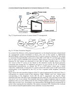
On the other hand, impact tests were carried out commercially (in Tokai Techno-research
Company) for square FRP tubes additionally. An example of Carbon UD specimen with the
usage of S-Inner 2 device as collapse trigger is given in Fig.18 to illustrate the preparation of
impact test. After the specimen is fixed on the test machine, the impactor of 120kg which
located from 12m height place fall freely to create the impact velocity of 55km/h (15.3 m/s)
when it crash the FRP tube. During the impact process, the sampling rate of load is selected
50µs (20 kHz) to obtain a series data of loads. Here something regrettable should be claimed.
In case of S-Inner 2 device usage, several duplicate specimens were not done in dynamic
compression. The reason will be explain in the following Discussions Section.
5.2 Results
5.2.1 Circular braided carbon/Epoxy FRP tubes
For Taper group tubes i.e. in the cases of taper triggers, the representative load-
displacement curves obtained from the axial quasi-static compression tests are shown in
Fig.19 (a). The common feature of all of the curves is that the loads increased rapidly in the
initial stage, reach a peak value and then dropped slightly. After that, the loads increased
again, and finally showed the characteristics of progressive crushing. Although, Taper-15
had the highest peak value at the initial crushing stage and a little different inclination
compared Taper-45 and Taper-75, the figures clearly indicate that the Taper group tubes
exhibit similar crushing load, in particularly, during the progressive crushing period.
However, as shown in Fig.19 (b), the situation is complicated for the Device group tubes.
That is, these tubes with different device type displayed distinct mean crush loads. In
detailed, the mean crush loads are 82.7kN for Inner-3; 35.8kN for Inner-5; 44.3kN for Outer-3
and 19.2kN for Outer-5. In addition, the mean loads of the tubes capped outer type device
were lower than their initial peak values. On the other hand, for the tubes with the inner
type trigger, the mean loads were retained at a higher level than the initial peak.
The usage situation of different triggers on the circular braided carbon/Epoxy FRP tubes in
quasi-static compression tests are summarized in Table 5. It is found that in the cases of
taper trigger, the crushing fashions of the circular FRP tubes are almost the same i.e. the
crushed walls were spread out towards both sides of the tube in two-side-bending mode
like a spreading flower. However, in the cases of device trigger usage, the fronds show one-
side-bending mode. The crush wall was split into pieces and bent inwards by Inner type
device or spread outwards by the Outer type device. Those internal fronds seem superposed
together tightly whereas, the external fronds are found to be separated. In addition, the
Es
values, calculated from the above Load-displacement curves, is also given in Table 5. Apart
from the crushing performance, such closed
Es values from 86.8 to 94.3 illustrate that the
Taper group tubes have the similar energy management. However, quite different
Es values
were obtained with different devices usage. It seems that Inner type device or a small radius
associates to higher energy absorption than Outer type device or a big radius. In the usage
Energy Technology and Management
46
of inner type device with a radius of 3mm, the highest value of 110.8 is achieved in C-Inner 3
specimen even compared to that of Taper group tubes.
Impactor: 120kg
Enlarged
Impact speed
55km/h (15.3 m/s)
12 m
(b) Fixed Carbon UD specimen
capped S-Inner 2 device
(a) Impact test machine
S-Inner 2
Carbon UD
Fix equipment
Fig. 18. Impact test machine and an example of Carbon UD specimen with the usage of S-
Inner 2 device as collapse trigger.
0
20
40
60
80
100
0 5 10 15 20 25 30
Displacement (mm)
load (kN)
Taper-75
Taper-45
Taper-15
0
20
40
60
80
100
0 5 10 15 20 25 30 35
Displacement (mm)
Load (kN)
Inner-3
Outer-3
Inner-5
Outer-5
(a) Taper trigger
(b) device trigger
Fig. 19. Typical load-displacement curves of circular braided carbon/Epoxy tubes with
different collapse triggers in quasi-static compression tests.
Es
Es
Es
Es
Es
Es
I
w
t
flatwall
bend
Es wt
EI s
U
ll
⋅⋅
⋅⋅
==
E, I, s l
t U
bend
U
bend