Nuclear Power Control, Reliability and Human Factors Part 10 ppt
Bạn đang xem bản rút gọn của tài liệu. Xem và tải ngay bản đầy đủ của tài liệu tại đây (3.9 MB, 30 trang )
Collapse Behavior of Moderately Thick Tubes Pressurized from Outside 3
(a) (b)
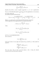
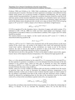
Fig. 2. Integrated primary system reactors of small size. (a) Westinghouse SMR-200 MWe
(Small Modular Reactor); (b) SMART-90 MWe (System Integrated Modular Advanced
Reactor). Reproduced from and
from (Ninokata, 2006), re spectively
1981; Tamano et al ., 1985; Yeh & Kyriakides, 1988)): such results are adequate in the range
of interest for oil industry, but become questionable for the thicker tubes required by the
nuclear applications mentioned above. In this range, collapse is dominated by yielding, but
interaction with buckling is still significant and reduces the pressure bearing capacity by an
amount that cannot be disregarded when safety is of primary concern.
The problem is similar to that of beam columns of intermediate slenderness, which also
fail because of interaction between yielding and buckling and that have been studied in
detail. A simple predictive formula was proposed in this context, which turns out to be
reasonably accurate for any slenderness and several code recommendations are based on it
(e.g., (EUROCODE 3, 1993)). An attempt at adapting such formula to the case of tubes was
made in (Corradi et al., 2008), but a direct modification was successful only in the medium
thin tube range, where the formula appears a s a feasible alternative to other proposals. With
increasing thickness the formula becomes conservative and only provides a, often coarse,
lower bound to the collapse pressure. A correction was proposed which, however, is to a
large extent empirical and based on fitting of numerical results.
259
Collapse Behavior of Moderately Thick Tubes Pressurized from Outside
4 Will-be-set-by-IN-TECH
In this study a different proposal is advanced, which is felt to better embody the physical
nature of the phenomenological behavior. Comparison shows that tubes behave essentially
as columns for D/t
≥ 25 − 30, but differences make their appearance and grow up to
significant values as this ratio diminishes. One reason is of geometric nature: the curvature
of the tube wall increases with diminishing D/t ratio and the analogy with a straight column
no longer applies. Another source of discrepancy is the stress redistribution capability that
thick tubes, in contrast to columns, possess and can exploit with significant benefit. This
aspect is not purely geometric: stress redistribution capability is still function of thickness,
but the possibility of exploiting it is influenced by material properties as well. By properly
interpreting these aspects, a formula is obtained that appears reasonably simple and accurate.
In addition, it is felt that it provides a deeper understanding on the collapse behavior of
cylindrical shells in a thickness range so far overlooked.
A comment on terminology is in order. Labels like “thick” or “thin” when applied to tubes
are to some extent ambiguous, since they are used in a different sense in different contexts. A
pipeline in deep sea water would be considered as a thick tube by an aerospace engineer and
as thin one by high pressure technology people. Often, the term “thin tube” is used when thin
shell assumptions, which consider stresses to be constant over the thickness, apply, but this
definition also becomes questionable outside the elastic range. In this study, reference is made
to the failure modality. A tube is called thin if it fails because of elastic buckling and thick when
only plastic collapse is relevant. In the intermediate region the two failure modalities interact,
with different weight for different slenderness. In moderately thin (or medium thin)tubes,
buckling is the critical phenomenon even if plasticity plays some role; similarly, in moderately
thick tubes failure is dominated by yielding, but interaction with buckling has non negligible
effects. The separation line is not very sharp (in oil industry applications, for instance, the
two phenomena have comparable weight), but the tubes of prominent interest in this study
definitively belong to the moderately thick range.
2. Collapse of cylindrical shells pressurized from outside
2.1 Basic theoretical results
Consider a cylindrical shell of nominal circular shape, with outer diameter D and wall
thickness t, subjected to an external pressure q. The shell is long enough for end effects to
be disregarded. The material is isotropic, elastic-perfectly plastic and governed by von Mises’
criterion. E and ν are its elastic constants (Young modulus and Poisson ratio, respectively)
and σ
0
denotes the tensile yield strength.
In the theoretical situation of a perfect tube, the limit pressure is given by the smallest among
the following values
Elastic buckling pressure q
E
= 2
E
1 − ν
2
1
D
t
D
t
−1
2
(1a)
Plastic limit pressure q
0
= 2σ
0
t
D
1
+
1
2
t
D
(1b)
The first expression is well known (Timoshenko & Gere, 1961), while equation (1b) was
established in (Corradi et al., 2005) and is a very good approximation to the exact value for
D/t
> 6.
260
Nuclear Power – Control, Reliability and Human Factors
Collapse Behavior of Moderately Thick Tubes Pressurized from Outside 5
Equations (1) apply to possibly thick tubes, which demand that stress variation over the
thickness be considered. Nevertheless, the average value S of the hoop stress σ
ϑ
is a
meaningful piece of information. Its value is dictated by equilibrium only and reads
S
=
1
2
q
D
t
(2)
For thick cylinders, peak stresses may exceed significantly the value (2), which is simply an
alternative, often convenient, way to refer to pressure. In p articular, the theoretical limits (1)
may be replaced by the expressions
S
E
=
E
1 − ν
2
1
D
t
−1
2
S
0
= σ
0
1
+
1
2
t
D
(3)
which are obtained by substituting in equation (2) either of the values (1) for q .
As the thickness decreases, local values approach their average and equation (2) becomes
meaningful as a stress intensity measure for sufficiently thin tubes, which are usually studied
by assuming σ
ϑ
≈ S. Also, the difference between the outer face of the tube, where the
pressure acts, and the middle surface, where the resultant of hoop stresses is applied, is
ignored. Within this f ramework, equations (1) become
Elastic buckling pressure p
E
= 2
E
1 −ν
2
t
D
3
(4a)
Plastic limit pressure p
0
= 2σ
0
t
D
(4b)
or, in terms of average hoop stress
F
E
=
E
1 − ν
2
t
D
2
F
0
= σ
0
(5)
Here (and in the sequel) p is used instead of q and F instead of S when computations are based
on thin shell assumptions.
In the theoretical situation, the two critical phenomena of elastic buckling and plastic collapse
are independent from each other. The quantity
Λ
=
q
0
q
E
=
1
κ
D
2
t
2
−
3
2
D
t
+
1
2
t
D
(6)
or, if thin shell approximation is adopted
Λ
=
p
0
p
E
=
1
√
κ
D
t
(7)
is known as slenderness ratio.Theparameter
κ
=
1
1 − ν
2
E
σ
0
(8)
is a dimensionless material property. Λ
= 1isthetransition value, separating the range of
comparatively thin tubes (Λ
> 1, q
E
< q
0
), theoretically failing because of elastic buckling,
from that of comparatively thick ones (Λ
< 1, q
0
< q
E
), when the critical situation is plastic
collapse. Fig. 3 depicts schematically the two failure modalities.
261
Collapse Behavior of Moderately Thick Tubes Pressurized from Outside
6 Will-be-set-by-IN-TECH
q q
elastic buckling mode
plastic collapse mechanism
Fig. 3. Failure modalities for a long tube
2.2 Effects of imperfections
The situation above is “theoretical” in that it refers to the ideal case of a perfect tube. A real tube
is unavoidably affected by imperfections, which introduce an interaction between plasticity
and instability. As a consequence, the ultimate pressure is lower than the theoretical value.
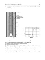
Fig. 4 depicts some aspects of the solution of a tube with an initial out of roundness (ovality):
the pressure-displacement curve grows up to a maximum value, corresponding to failure, and
then decreases; at the maximum, the tube is only partially yielded, i.e., plastic zones (in color)
nowhere spread across the entire tube thickness (Fig. 4a). The “four hinge” mechanism is
is attained in t he post-collapse portion of the curve only (Fig. 4b). Failure occurs because
of buckling of the partially yielded tube: even if not forming a mechanism, plastic zones reduce
the tube stiffness and make the buckling load diminish. Failure corresponds to the elastic
buckling of a tube of variable thickness, co nsisting of the current elastic portion.
(a) (b)
Fig. 4. Response of an initially oval tube. (a) plastic zones at failure; (b) four hinge
mechanism in the post-collapse phase
To compute the failure pressure, complete elastic-plastic, large displacement analyses up to
collapse are required, explicitly accounting for different kinds of possible imperfections. A
systematic study was undertaken at the Politecnico di Milano and results are summarized in
(Corradi et al., 2009; Luzzi & Di Marcello, 2011). Imperfections of both geometrical (initial out
of roundness, non uniform thickness) and mechanical (initial stresses) nature were considered.
As in a sense expected, it was found that all of them have similar consequences, causing a
significant decay of the failure pressure with respect to the theoretical one for slenderness
ratios close the transition value, with interaction effects diminishing as Λ departs from one
in either direction. In any case, some decay was experienced in the entire range 0.2
≤ Λ ≤
5, covering all situations of practical interest, except possibly high pressure technology or
262
Nuclear Power – Control, Reliability and Human Factors
Collapse Behavior of Moderately Thick Tubes Pressurized from Outside 7
aerospace engineering. The slenderness ratio of tubes for the aforesaid nuclear applications
is low, but not enough to disregard the effects of interaction with instability: the IRIS steam
generator tubes bundles, if sized according to Code Case N-759, correspond to Λ
≈ 0.4.
When the study was started, Code Case N-759 was not available and ASME Section III rules
required an external diameter to thickness ratio D/t
= 8.27 (Λ ≈ 0.25). Such a design is
surprisingly severe and it was felt that the code assumed an a-priori conservative attitude f or
tubes belonging to a range scarcely studied both from the numerical and the experimental
points of view, reflecting a substantial lack of knowledge on the phenomena involved. The
numerical campaign was intended a s a first step toward the definition of a suitable failure
pressure, a reliable reference value permitting the derivation of an allowable working pressure
through the use o f a proper s a fety factor (Corradi et al., 2008). Computations had to include
imperfections (one drawback of ASME III rules was that imperfections were not explicitly
considered) but, since the effects of all of them were found to be similar, only the most
significant was considered. This was identified with an initial out of roundness, or ovality,
defined by the dimensionless parameter
W
=
D
max
− D
min
D
(9)
where D
max
and D
min
are the maximum and minimum diameters of the ellipsis portraying the
external surface of the tube (see Fig. 8a in the subsequent section) and D is their average value
(nominal external diameter). To the failure pressure q
C
computed in this way (a reasonable
choice for the reference value) a safety factor is appl ied so as to reproduce ASME Section III
sizing for medium thin tubes, a well known and well explored range, in which the code can
be assumed to consider the proper safety margin (see (Corradi et al., 2008) for details). If the
same factor is applied to thicker tubes as well, significant thickness saving is achieved without
jeopardizing safety.
The requirement that the reference pressure be computed numerically makes the procedure
cumbersome and an attempt at reproducing numerical results with an empirical formula was
made ( Corradi et al., 2008). The formula is adequate for practical purposes, but the approach
is not completely satisfactory for a number of reasons: (i) the formula is involved and a
simpler expression is desirable; (ii) its empirical nature does not help the understanding of
the mechanical aspects of the tube behavior, and (iii) the formula is not equally accurate for all
materials. Its coefficients were determined by considering the material envisaged for the IR IS
SG tube bundles, i.e. Nickel-Chromium-Iron alloy N06690 (INCONEL 690) and the formula is
fairly precise for 700
≤ κ ≤ 1100, where κ is defined by equation (8). Some materials, however,
either because of high tensile yield strength σ
0
or low Young modulus E, have values o f κ
significantly below the lower limit; in these instances, the formula entails errors up to 10%,
even if always on the safe side. Table 1 lists some of the materials investigated, with the
properties employed in (Corradi et al., 2008) for computations and that will be used in this
study as well. Trouble was experienced with aluminum and titanium alloys.
3. Interaction domains
3.1 Preliminary: load bearing capacity of struts
The proposal advanced in this study originates from the approach used to evaluate the
collapse load of compressed columns, which is briefly outlined to introduce the procedure.
Consider the strut in compression illustrated in figure 5a. Its center line has an initially
sinusoidal shape of amplitude U. The critical section, obviously, is the central one, where
263
Collapse Behavior of Moderately Thick Tubes Pressurized from Outside
8 Will-be-set-by-IN-TECH
material E (GPa) σ
0
(MPa) ν κ
D
t
Λ=0.2
stainless steel UNS S31600 200 200 0.31 1106 7.44
nickel-chromium-iron alloy N06690 183 240 0.29 832 6.56
aluminum alloy UNS A96061 70 240 0.35 332 4.46
titanium alloy UNS R56400 110 830 0.34 150 3.28
Table 1. Material p roperties for the considered materials
P
U
M
1
2
M
0
M
e
N
N
0
=N
e
(a) (b)
l
Fig. 5. Compressed column with initial imperfection
the axial force is N
= P (compression positive) and the bending moment M is expressed as
M
= PU
1
1 −
P
P
E
(10)
where P
E
is the Euler buckling load (P
E
= π
2
EI/l
2
)and1/
(
1 − P/P
E
)
the magnification factor.
Equation ( 10) is exact in the elastic range since the initial i mperfection has the same shape as
the buckling mode (Timoshenko & Gere, 1961).
The behavior of the cross section is subsumed by the interaction diagrams in figure 5b. Line 1 is
the elastic limit and for N
− M values on it one fiber is about to yield; line 2 is the limit curve,
bounding the domain of N
− M combinations that can be borne. The gray zone is the elastic
plastic region, corresponding to partially yielded sections. N
e
and M
e
are the values that
individually bring the section at the onset of yielding, N
0
and M
0
the corresponding values
exhausting the sectional bearing capacity. Obviously, it is N
e
= N
0
, since in pure compression
stresses are uniform. The elastic limit is given by
N
N
e
+
M
M
e
= 1 (11a)
while the equation of the limit curve depends on the sectional shape. For rectangular cross
sections one has
N
N
0
2
+
M
M
0
= 1 (11b)
with M
0
=
3
2
M
e
.
264
Nuclear Power – Control, Reliability and Human Factors
Collapse Behavior of Moderately Thick Tubes Pressurized from Outside 9
By substituting equation (10) for M into (11a), a quadratic equation for P is obtained, which
is easily solved to give the load P
el
exhausting the elastic resources of the strut and bounding
from below its load bearing capacity P
C
. The same procedure applied with (11b) replacing
(11a) provides an upper bound to P
C
. In fact, at collapse some fibers of the central section
are still elastic (Fig. 6) and the corresponding N
− M point is inside the limit domain. Some
collapse situations are indicated by dots in figure 5b (the representation is qualitative, the
location of the points being influenced to some extent by the strut slenderness). Observe
also that the expression (10) for the maximum bending moment looses its validity outside the
elastic range.
Fig. 6. Typical column at collapse: plastic strains develop in the red zone
A reasonable approximation to the collapse load is obtained by assuming that the N
− M
points at collapse are located on the straight line
N
N
0
+
M
M
0
= 1 (12)
(dashed in figure 5b) and that the elastic relation (10) holds up to this point. One obtains
P
C
=
1
2
⎛
⎝
N
0
+ P
E
1
+ U
N
0
M
0
−
N
0
+ P
E
1
+ U
N
0
M
0
2
−4N
0
P
E
⎞
⎠
(13)
For rectangular (b
×h) cross sections it is N
0
= σ
0
bh, M
0
=
1
4
σ
0
bh
2
and the column slenderness
can be written as λ
= 2
√
3
l
h
. By considering the slenderness ratio
Λ
=
N
0
P
E
=
λ
λ
0
(14)
where
λ
0
= π
E
σ
0
(15)
is the transition slenderness (a material property) and by introducing the dimensionless
imperfection measure
W
=
U
l
(16)
one can write equation (13) in the form
P
C
=
1
2
N
0
+ P
E
(
1 + Z
)
−
(
N
0
+ P
E
(
1 + Z
))
2
−4N
0
P
E
(17a)
265
Collapse Behavior of Moderately Thick Tubes Pressurized from Outside
10 Will-be-set-by-IN-TECH
with
Z
= U
N
0
M
0
=
2
√
3
λ
0
ΛW (17b)
Equation (17) is a good approximation to the numerically computed failure load of
compressed columns, as depicted in Fig. 7 where results for two materials with strongly
different properties and a few initial imperfection magnitudes are compared. Several codes,
including EUROCODE 3, base their recommendations on it (Dowling, 1990).
(a) INCONEL 690 (λ
0
= 86.8) (b) Titanium alloy (λ
0
= 36.2)
Fig. 7. Formula (17) vs computed results (dots). Λ defined by equation (14)
3.2 Interaction domain for an oval tube
Consider now a cylindrical shell with an initial imperfection controlled by W, equation (9), as
illustrated in figure 8. Because of W, the external pressure q will cause, besides compressive
hoop stresses, a bending moment with peak values given by the relation
M
= M
I
1
1 −
q
q
E
(18a)
where
M
I
=
1
8
qD
2
W (18b)
is the value predicted within the small displacements framework (geometric linearity) and q
E
is the Euler buckling pressure (1a). The expression (18) for M is exact in the elastic range if the
initial imperfection has the same shape as the buckling mode (Timoshenko & Gere, 1961).
As for beam columns, the behavior of the tube wal l can be interpreted on the basis of suitable
interaction domains, with the external pressure q playing the role of the compression force and
equation (18) replacing (10) to express the peak value of the bending moment. The domains
are sketched in figure 8b: as in the equivalent picture for the strut, line 1 bounds the elastic
266
Nuclear Power – Control, Reliability and Human Factors
Collapse Behavior of Moderately Thick Tubes Pressurized from Outside 11
Fig. 8. Interaction domain for the tube cross section
region and line 2 is the limit curve. Reference values are assumed as follows (Corradi et al.,
2008)
q
e
= 2σ
0
t
D
1
−
t
D
q
0
= 2σ
0
t
D
1
+
1
2
t
D
(19a)
M
e
=
σ
0
√
1 − ν + ν
2
1
4
b
2
− a
2
2
− a
2
b
2
ln
b
a
2
2b
2
ln
b
a
−
(
b
2
− a
2
)
M
0
≈
σ
0
t
2
2
√
3
(19b)
where q
e
, M
e
and q
0
, M
0
are the pressure and moment values that individually bring the tube
at the onset of yielding and exhaust its load bearing capacity. b
= D/2 and a = b −t are the
external and internal nominal radii, respectively.
The values above refer to materials governed by von Mises’ criterion. Elastic stresses are
computed from the well known plane solutions for a round cylinder under external pressure
and for a curved beam subject to constant bending moments (Timoshenko & Goodier, 1951)
and the values of q
e
, M
e
are obtained on this basis. q
0
is given by equation (1b), rewritten
for completeness; the value (19b)
2
of M
0
actually refers to a straight beam and, for tubes thick
enough to demand that curvature be considered, entails an error not completely negligible but
acceptable: bending moments being caused by imperfections, only the portion of the domains
close to the q axis is of interest.
The interaction domains for the tube and the strut of rectangular cross section exhibit some
differences that become significant with increasing tube thickness. First of all, while the ratio
M
0
/M
e
maintains more or less the value of 1.5, q
0
exceeds q
e
by an amount that must be
considered for D/t
< 25. Moreover, in thick tubes the hoop stresses due to pressure are not
uniform, which provides additional stress redistribution capabilities, so that the limit curve is
expected to be external to that of the equivalent strut (the situation is sketched in figure 8b,
where curve 3 (thinner) portrays the parabola (11b) with q replacing N). As a consequence,
the region of partially yielded tubes (in gray), which contains the collapse situations, widens
considerably, augmenting the uncertainties in estimating the failure pressure.
Nevertheless, the extension to tubes of the beam-column procedure is spontaneous and an
attempt i n this sense is made by introducing equation (18) for M in the linear expression
q
q
0
+
M
M
0
= 1 (20)
267
Collapse Behavior of Moderately Thick Tubes Pressurized from Outside
12 Will-be-set-by-IN-TECH
corresponding to the dashed segment in Fig. 8b. As for columns, a second order equation is
obtained; its smallest root reads
q
C
=
1
2
q
0
+ q
E
(
1 + Z
)
−
(
q
0
+ q
E
(
1 + Z
))
2
−4q
0
q
E
(21a)
with
Z
=
√
3
2
D
t
+
1
2
W (21b)
The analogy with equation (17a) is immediately apparent.
(a) INCONEL 690 (κ = 832) (b) Titanium alloy (κ = 150)
Fig. 9. Formula (21) vs computed results (dots). Λ defined by equation (6)
The results provided by equation (21) are plotted in Fig. 9 (solid lines). Dots refer to the
results computed in (Corradi et al., 2009), where indication on the assumptions made, the
finite element model used and the solution procedure adopted can be found. For graphical
purposes, the ultimate pressure is expressed in terms of the average hoop stress equation (2).
Agreement is g ood for Λ
> 1 but, as the thickness increases, lower bounds rather than good
approximations are obtained. It can be concluded that thin or moderately thin tubes behave
essentially as straight columns of rectangular cross section, but some fundamental aspects of
the structural re sponse change drastically as the thickness increases beyond a certain limit.
A first reason for this change is of purely geometric nature, i.e. it depends on the value of D/t
only. For comparatively large values the tube wall behaves essentially as a straight column,
but curvature increases with diminishing D/t and differences become more and more evident.
Secondly, thick tubes exhibit stress redistribution capabilities that columns do not have and
this provides additional resources in terms of overall strength. It must be observed that stress
redistribution capability depends on D/ t only, but the possibility of actually exploiting it is
conditioned by tube slenderness Λ which, as equation (6) shows, depends on both D/t and
the material properties subsumed by the dimensionless parameter κ, equation (8).
Fig. 9 indicates that the second effect is dominant. Because of the strong difference in κ, Λ
= 1
corresponds to D/t
≈ 30 for INCONEL 690 and to D/t ≈ 13 for titanium alloy. The two
268
Nuclear Power – Control, Reliability and Human Factors
Collapse Behavior of Moderately Thick Tubes Pressurized from Outside 13
pictures do show some differences, but not as strong as the discrepancy between the two D/t
values would suggest: computed results for titanium depart from formula predictions for a
slightly greater Λ than for INCONEL, but the overall response seems to depend more on Λ as
a whole than on D/t only.
In any case, equation (21a) provides conservative estimates for the failure pressure of thick
tubes. In (Corradi et al., 2008) this result was considered effectively as a lower bound and
a corresponding upper bound, consisting in the plastic collapse load of the ovalized tube
computed by neglecting geometry changes, was associated to it. The two bounds were
combined by introducing a suitable weighting factor, determined by fitting a number of
computed results for tubes of different materials (including those listed in Table 1). As it
was already mentioned, the procedure produced acceptable results, but it is felt that it could
be both simplified and improved.
4. The proposed procedure
Both equations (17) for columns and (21) for cylindrical shells predict that the failure
pressure coincides with the theoretical limit when the relevant parameter Z vanishes. This
obviously occurs for any slenderness ratio when no imperfections are present (W
= 0) but,
independently of the presence of imperfections, both structures are expected to become stocky
enough to make negligible interaction with buckling. In other words, it should be Z
= 0for
any W when slenderness attains a sufficiently low value.
Equation (17b) in fact implies Z
→ 0forΛ → 0, so that one obtains P
C
= N
0
for infinitely
stocky columns, independently of the imperfection amplitude. However, to give Z
= 0for
W
= 0, equation (21b) requires
D
t
= −
1
2
, a value with no physical meaning. This is another
reason for the increasingly conservative nature of the approximation as Λ diminishes.
The remarks above suggest that the approximation can be improved by operating on the
expression (21b) of Z so to make it vanish for sufficiently small D/t. A minimal choice
is D/t
= 2, the lowest possible v alue, which however turns out to be still too restrictive.
Moreover, the discussion in the preceding section shows that, to obtain an approximation
reasonably accurate for all materials, slenderness ratio Λ is preferable to D/t as a measure of
the limit stockiness. On the basis of the numerical r esults in (Corradi et al., 2009), this can be
reasonably identified with Λ
= 0.2 and the corresponding values of D/t for different materials
can be obtained by numerically solving equation (6). For the materials considered in Table 1,
the resulting values, labeled as
(D/t)
Λ=0.2
, are listed in the last column.
The correction consists in replacing the term
(D/t + 1/2) with (D/t − (D/t)
Λ=0.2
) in
equation (21b). This improves the approximation for Λ
< 1, but shifts t he curves upward
everywhere by an amount of some significance, even if not dramatic and diminishing with
increasing Λ . For compensation, the imperfection amplitude is artificially increased by
multiplying W by a factor that, empirically, was identified with 1.2. Thus, the expression
for Z becomes
Z
=
√
3
2
D
t
−
D
t
Λ=0.2
1.2 W (22)
If equation (21b) is replaced by the expression above, equation (21a) produces the results
depicted in Fig. 10 for the f our materials listed in Table 1, covering a range of values of κ that
can be regarded as exhaustive. Plots depart from the value of Λ corresponding to D/t
= 5,
which is different for different materials. Formula predictions show a very good agreement
throughout with numerical results ( dots). For materials w ith low values of κ (aluminum and
269
Collapse Behavior of Moderately Thick Tubes Pressurized from Outside
14 Will-be-set-by-IN-TECH
(a) Stainless steel (κ = 1106) (b) INCONEL 690 (κ = 832)
(c) Aluminum alloy (κ = 332) (d) Titanium alloy (κ = 150)
Fig. 10. Proposed formula vs computed results. Λ defined by equation (6)
titanium alloys) they remain a little conservative for stocky tubes, but improvement with
respect to the unbridged formula is significant.
5. Shortcomings of thin shell approximation
In the formula above the theoretical limit values are defined by equations (1) and, as a
consequence, the slenderness ratio by equation (6). Use of these expressions is m andatory in
a context that includes thick and moderately thick tubes, in that they incorporate the effects of
stress redistribution over the wall thi ckness, which were seen to be significant and which the
“thin shell” equations (4), (7) ignore. Nevertheless, the latter expressions often are preferred
and the implications of their use are worth exploring.
270
Nuclear Power – Control, Reliability and Human Factors
Collapse Behavior of Moderately Thick Tubes Pressurized from Outside 15
(a) Stainless steel (κ = 1106) (b) INCONEL 690 (κ = 832)
(c) Aluminum alloy (κ = 332) (d) Titanium alloy (κ = 150)
Fig. 11. Results obtained with thin shell approximation. Λ defined by equation (7)
Formally, modifications are straightforward. It suffices to replace in equation (21a) q
0
and q
E
with p
0
and p
E
, as defined by equations (4). One obtains
p
C
=
1
2
p
0
+ p
E
(
1 + Z
)
−
(
p
0
+ p
E
(
1 + Z
))
2
−4p
0
p
E
(23a)
The value of Z still could be given by equation (22), whith
(D/t)
Λ=0.2
computed from
equation (7). However, the choice for a limiting value of D/t associated to a material
independent slenderness ratio is justified by the dominant effect of stress redistribution,
associated with Λ. Thin shell approximation does not account for stress redistribution and the
only cause of departure of the tube response from that of the straight column is the geometric
curvature, so that a limiting value of D/t seems the most appropriate choice. An acceptable
271
Collapse Behavior of Moderately Thick Tubes Pressurized from Outside
16 Will-be-set-by-IN-TECH
compromise, valid for all materials, turns out to be (D/t)
lim
= 6andonecanwrite
Z
=
√
3
2
D
t
−6
1.2 W (23b)
The results provided by equations (23a) are depicted in Fig. 11. Results are not as accurate
as those in Fig. 10, but still acceptable in the moderately thin and thin tube range. As
well expected, predictions become grossly conservative with increasing thickness, which
underlines the importance of properly accounting for stress redistribution. To assess the
pressure bearing capacity of the tube, thin shell theory is adequate only to more than
moderately thin tubes (i.e., thinner than those for whi c h an elastic solution still is acceptable)
and a formulation aiming at covering the entire slenderness range must consider more precise
expressions. One cannot even claim that these shortcomings are compensated by greater
simplicity: equations (23a) are not simpler; only they are based on more usual definitions.
6. Conclusions
Long cylindrical shells subjected to external pressure have been considered. The study was
motivated by the necessity of assessing the collapse behavior of the moderately thick tubes
involved by some recent nuclear power plant proposals, but tubes of any slenderness were
considered, even if little attention was devoted to very thin tubes, which buckle when still
elastic according to well known modalities and that do not need additional investigation.
In previous papers it was demonstrated that a reliable reference value for the pressure causing
tube failure can be obtained by performing complete non linear finite element computations
under suitable assumptions. Purpose of this study was the derivation of an accurate and
simple formula permitting the definition of this value without performing numerical analyses.
It does not seem too daring to state that this goal has been attained with equations (21a), (22):
the formula is fairly simple and the results it provides are in good agreement with numerical
outputs for different materials, imperfection amplitudes and slenderness ratios. Obviously,
only a few materials, imperfections and slendernesses have been checked, but the range of
parameters used is wide enough for this statement to be considered of general validity.
The formula can be used both for preliminary design purposes and as a reliable reference
value for the definition of allowable working pressure. This second aspect, however, no
longer is a must: since Code Case N-759 was approved, tubes can be sized adequately by
using existing regulations and alternatives are not r equired. In the authors’ opinion, however,
this fact does not diminish the interest of the result achieved. The ingredients used to build
the formula enlighten some aspects of the collapse behavior of moderately thick tubes, a
range so far little explored. Tu bes of intermediate slenderness fail because of interaction
between buckling and plasticity, but differences show up at slendernesses a bout the transition
value. Medium thin tubes behave essentially as straight columns and column formulas can be
employed with straightforward modifications. As thickness increases, however, the geometry
dependent effect of curvature and the slenderness dependent effect of stress redistribution
enter the picture and the tube wall no longer behaves as a straight beam. To account for these
aspects, a correction was introduced to the original formula. The accuracy of the consequent
results can be taken as the indication that the fundamental aspects of the mechanical behavior
are correctly represented.
272
Nuclear Power – Control, Reliability and Human Factors
Collapse Behavior of Moderately Thick Tubes Pressurized from Outside 17
7. Acknowledgment
Authors express their gratitude to Mr Giovanni Costantino and Mr Manuele Aufiero for
performing some of the computations used in this study.
8. References
ASME (2007). Code Case N-759: Alternative rules for determining allowable external pressure
and compressive stresses for cylinders, cones, spheres and formed heads, In:
BPVC-CC-N-2007 Nuclear Code Cases; Nuclear components, ASME International, 2007.
ISBN 0791830764.
Budiansky B. (1974). Theory of buckling and post-buckling behaviour of elastic structures.
Advances in Applied M echanics, Vol. 14, Issue C, 1974, 1-65, ISSN 0065-2156.
Carelli M.D.; Conway L.E.; Oriani L.; Petrovic B.; Lombardi C.V.; Ricotti M.E.; Baroso A.C.O.;
Collado J.M.; Cinotti L.; Todreas N.E.; Grgic D.; Moraes M.M.; Boroughs R.D.;
Ninokata H.; Ingersoll D.T. & O riolo F. (2004). The design and safety features of t he
IRIS reactor. Nuclear Engineering and Design, Vol. 230, No. 1-3, May 2004, 151-167,
ISSN 0029-5493.
Carelli M.D. (2009). The exciting journey of designing an advanced reactor. Nuclear Engineerin g
and Design, Vol. 239, No. 5, May 2009, 880-887, ISSN 0029-5493.
Cinotti L.; Bruzzone M.; Meda N.; Corsini G.; Lombardi C.V.; Ricotti M. & Conway L.E. (2002).
Steam generator of t he International Reactor Innovative and Secure, Proceedings of the
Tenth International Conference on Nuclear Engineering (ICONE), Ar lington, VA, Paper
No. ICONE10-22570.
Corradi L.; Luzzi L. & Trudi F. (2005). Collapse of thick cylinders under radial pressure and
axial load. ASME Journal of Applied Mechanics, Vol. 72, No. 4, July 2005, 564-569, ISSN
0021-8936 .
Corradi L.; Ghielmetti C. & Luzzi L. (2008). Collapse of thick tubes pressurized from outside:
an accurate predictive formula. ASME Journal of Pressure Vessel Technology, Vol. 130,
No. 2, May 2008, Paper 021204_1-9, ISSN 0094-9930.
Corradi L.; Di Marcello V.; Luzzi L. & Trudi F. (2009). A numerical assessment of the
load bearing capacity of externally pressurized moderately thick tubes. International
Journal of Pressure Vessels and Piping, Vol. 86, No. 8, August 2009, 525-532, ISSN
0308-0161.
Dowling P.J. (1990). New directions in European structural s teel design, Journal of
Constructional Steel Research, Vol. 17, No. 1-2, July 1990, 113-140, ISSN 0143-974X.
EUROCODE 3 (1993). Design of Steel Structures. Part 1.1: General Rules and Rules for
Building, ENV 1-1, Brussels, 1993.
Haagsma S.C. & Schaap D. ( 1981). C ollapse resistance of submarine pipelines studied. Oil &
Gas Journal, No. 2, February 1981, 86-91, ISSN 0030 1388.
IAEA (2007). Status of Small Reactor Designs without Onsite Refueling, International Atomic
Energy Agency, IAEA-TECDOC-1536, ISSN 1011- 4289.
Ingersoll D.T. (2009). Deliberately small reactors and the second nuclear era, Progress in Nuclear
Engineering, Vol. 51, No . 4 -5, May-July 2009, 589-603, ISSN 0149-1970.
Karahan A. (2010). Possible design improvements and a high power density fuel design
forintegraltypesmallmodularpressurizedwaterreactors,Nuclear Engineering and
Design, Vol. 240, No. 10, October 2010, 2812-2819, ISSN 0029- 5493.
273
Collapse Behavior of Moderately Thick Tubes Pressurized from Outside
18 Will-be-set-by-IN-TECH
Lo Frano R. & Forasassi G. (2009). Experimental evidence of imperfection influence on
the buckling of thin cylindrical shells under uniform external pressure. Nuclear
Engineering and Design, Vol. 239, No. 2, February 2009, 193-200, ISSN 0029-5493.
Luzzi L. & Di Marcello V. (2011). Collapse of nuclear reactor SG tubes pressurized from
outside: the influence of imperfections. ASME Journal of Pressure Vessel Technology,
Vol. 133, No. 1, February 2011, Paper 011206_1-6, February 2011, ISSN 0094-9930.
Mendelson A. (1968). Plasticity: Theory and Applications, McMillan, New York.
Ninokata H. (2006). A comparative overwiev of the thermal hydraulic characteristics of
integrated primary systems nuclear r eactors, Nuclear Engineering and Technology,Vol.
38, No. 1, February 2006, 33-44, ISSN 1738-5733.
Tamano T.; Mimaki T. & Yanagimoto S. (1985). A new empirical formula for collapse r esistance
of commercial casing, Nippon Steel Technical Report, No. 26, 1985, 19-26, ISSN 0300
306X.
Timoshenko S. & Gere J.M. (1961). Theory of Elastic Stability, McGraw-Hill, New York.
Timoshenko S. & Goodier J.N. (1951). Theory of Elasticity, McGraw-Hill, New York.
Yeh M.H. & Kyriakides S. (1988). Collapse of deepwater pipelines. ASME Journal of Energy
Resources Technology, Vol. 110, No. 1, March 1988, 1-11, ISSN 0195-8954.
274
Nuclear Power – Control, Reliability and Human Factors
15
Resistance of 10GN2MFA-A
Low Alloy Steel to Stress Corrosion
Cracking in High Temperature Water
Karel Matocha
1
, Petr Čížek
1
, Ladislav Kander
1
and Petr Pustějovský
2
1
Material & Metallurgical Research, Ltd., Ostrava,
2
VÍTKOVICE Heavy Machinery, J.S.C., Ostrava,
Czech Republic
1. Introduction
In the second half of the last century the pressure vessel and the cold and hot collector
bodies, ranking among the most stress and corrosion exposed components of the WWER
1000 (Water-Water Energy Reactor) horizontal steam generator (SG), were manufactured of
the low alloy steel of type 10GN2MFA, the chemical composition of which is shown in tab.
1 (IAEA-EBP-WWER-07, 1997).
C M
n
Si S P Cr Ni Mo V Cu
0,08-0,12 0,80-1,10 0,17- 0,37 ≤ 0,020 ≤0,020 ≤0,030 1,8-2,3 0,40-0,70 0,03-0,07 ≤0,30
Table 1. Chemical composition of 10GN2MFA steel in line with standard element mass
content, [%]
In the period from 1986 to 1995 cracks due to stress corrosion cracking (SCC) have been
revealed after 7000 to 60 000 hours of operation in the ligaments between tube holes on the
cold collectors in 25 steam generators at 9 units operated in the former Soviet Union
(WWER SC 076,1993; Matocha, Wozniak, 1996, IAEA-EBP-WWER-07, 1997).
The cause analysis of collector cracking, carried out in the former Soviet Union, showed that
the steel used, in all cases where cracking was experienced, has been produced by the open
hearth furnace process (IAEA-EBP-WWER-07, 1997). Open heart furnace melted collector
metal had local impurity concentrations, including manganese sulphide, which have
deleterious effect on SCC resistance of low alloy steels in high temperature water
environment.
Since the beginning of 1989 a number of modifications have been introduced in the former
Soviet Union in the steam generators or in their operational conditions process (IAEA-EBP-
WWER-07, 1997). One of them was the modification of the steelmaking process. Only steel
produced by electroslag remelting has been used for the manufacturing of collector bodies.
The electroslag remelting process (ESR) allows to enhance considerably micro-cleanliness
of the steel and consequently the resistance of the 10GN2MFA steel to SCC in high
temperature water environment.
In the period from 1991 to 1994, the eight steam generators were manufactured in
VÍTKOVICE, J.S.C. for WWER 1000 Temelín NPP. The collector bodies of Temelín NPP
Nuclear Power – Control, Reliability and Human Factors
276
steam generators were made of doubly vacuum treated 10GN2MFA steel (first on DH
equipment and then by pouring in vacuum) so as to minimize the gas concentration and to
secure a homogeneous chemical composition. Steps were taken in all heats to keep down the
content of impurity elements. The typical chemical composition of the steel is shown in tab.
2 (WWER SC 076, 1993).
C Mn Si S P Cr Ni Mo V Cu
0,10 0,86 0,27 0,008 0,009 0,19 2,16 0,43 0,05 0,08
Table 2. The typical chemical composition of 10GN2MFA steel of Temelín NPP collector
bodies [mass %]
No occurrence of environmentally assisted cracking has been noticed till now after
approximately 79 000 hours of operation of the steam generators at Temelín NPP.
According to contemporary Russian technical specifications TU 0893-014-00212179-2004, the
WWER 1000 SG collector body must be manufactured of the electroslag remelted
10GN2MFA steel (10GN2MFA-S). Sulphur content must be kept lower than 0,005% and the
concentration of phosphorus must be lower than 0,008%. The requirement for the chemical
composition and tensile properties of the 10GN2MFA-S steel are summarized in tab.3 and
tab.4.
C Mn Si P S Cu Ni Cr Mo V Ti Al
min. 0,08 0,80 0,17 - - - 1,80 - 0,40 0,03 - 0,005
max. 0,12 1,10 0,37 0,008 0,005 0,30 2,30 0,30 0,70 0,07 0,015 0,035
Table 3. The requirements for the composition of the steel used for the manufacture of the
WWER 1000 collector body.
Test
temperature
Yield point Yield strength
Tensile
strength
Elongation
Reduction of
Area
+20
o
C 345-590 MPa 540-700 MPa 18% 60%
350
o
C min. 295 MPa min. 490 MPa 15% 55%
Table 4. Requirements for the tensile properties of the 10GN2MFA steel.
In the course of the nineties of the last century, the significantly modernised technology of
the 10GN2MFA steel production (electric arc furnace, refining in ladle furnace, vacuum
degassing, bottom pouring under argon protection into mould) was established in
VÍTKOVICE Heavy Machinery, J.S.C. It enables to guarantee the content of sulphur lower
than 0,005% and the content of phosphorus lower then 0,008%.
However Vítkovice Heavy Machinery J.S.C. does not own the electroslag remelting plant.
To be able to manufacture the WWER 1000 collector bodies for AES 2006 reactor plant, it
was necessary to prove that there is no difference between electroslag remelted 10GN2MFA
steel (10GN2MFA-S) and the steel manufactured by modernised VÍTKOVICE Heavy
Machinery technology (10GN2MFA-A) from the point of view of fracture behaviour and
resistance to stress corrosion cracking in high temperature water environment. For this
purpose three forgings of WWER 1000 SG collector body were manufactured in VÍTKOVICE
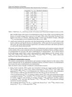
Heavy Machinery, J.S.C. (see Fig.1).
Resistance of 10GN2MFA-A
Low Alloy Steel to Stress Corrosion Cracking in High Temperature Water
277
Fig. 1. Dimensions of the collector body after rough machining
This work summarizes the results of the evaluation of the tensile properties, fracture
behaviour and resistance to stress corrosion cracking in high temperature water
environment of the collector body forging No 1 material. The resistance to SCC in high
temperature water environment was evaluated both in laboratories of MATERIAL &
METALLURGICAL RESEARCH, Ltd. (M&MR, Ltd.) and also in laboratories of
CNIITMASH, a joint-stock company, Moscow (Russia). The testing procedure used was
proposed by CNIITMASH. The obtained results were compared with the results published
by CNIITMASH for the 10GN2MFA-S steel (Yukhanov,V.A. & co-workers, 2009,
Yukhanov,V.A. & co-workers, 2010).
2. Testing material and experimental techniques
The testing ring ZK1 (see Fig.1) after simulated post weld heat treatment was used as a
testing material. Its chemical composition is shown in tab.5.
C Mn Si P S Cu Ni Cr Mo V Ti Al
0,12 0,90 0,22 0,006 0,002 0,05 1,88 0,048 0,55 0,042 0,004 0,021
Table 5. The chemical composition of the testing material.
Metallographic analysis proved very low content of non-metallic inclusions of globular
shape. The fine grained microstructure of the steel is bainitic with the average initial
austenitic grain size G= 6-7.
Fig.2 illustrates schematically the location and orientation of the test specimens used for
the determination of tensile and fracture characteristics (impact tests, fracture mechanics
tests) and the round bar tests used for the evaluation of resistance to SCC by slow strain
rate test.
Nuclear Power – Control, Reliability and Human Factors
278
Fig. 2. Orientation of the test specimens in the testing block
As the characteristic feature of the fracture behaviour of 10GN2MFA steel at temperatures
from 20°C to 320°C was found to be a ductile stable crack growth (Matocha,K., Wozniak,J.,
1995, Matocha,K., Rožnovská,G. & Hanus, V.,2007), the variation in J with crack growth
(J-R curve) was investigated at 290°C using multiple specimen method . 1CT (compact
tension, 25 mm in thickness) specimens were used for the determination of
J
IC
. Tests were
carried out in a stroke control at the speed of 0,5 mm/min. in accordance with GOST 25.506-
85 on MTS 500 kN servo-hydraulic testing machine. Loading of the test specimens was
realized in the three zone furnace specially developed for the determination of the fracture
toughness at elevated temperatures. The design of the furnace enables to measure the crack
mouth opening during the test (see Fig.3).
The slow strain rate tests of both round bar test specimens 5 mm in diameter and fatigue
pre-cracked 1CT test specimens (ISO 7539-7:2005, ISO 7539-9:2003) were used for the
evaluation of the resistance of the 10GN2MFA-A steel to SCC in high temperature water
environment (260°C, 290°C). The testing parameters for the evaluation of resistance of the
steel against stress corrosion cracking (strain rates, initial dissolved oxygen content) were
proposed by CNIITMASH.
SCC tests were performed in static autoclave 11 l in volume fitted with INOVA servo-
hydraulic testing machine. Slow strain rate tests of round bar test specimens were carried
out under stroke control in demineralised water at temperatures 260°C and 290°C at strain
rate 1,4.10
-7
s
-1
. Initial concentrations of dissolved oxygen 0,5 ppm, 1,5 ppm and 4,5 ppm
were obtained by adding 50% H
2
O
2
into demineralised water which was got rid of carbon
dioxide. The susceptibility to SCC is evaluated on the basis of a comparison of reduction of
area determined in air and in water environment at the same testing temperature. Slow
strain rate tests of the fatigue pre-cracked 1CT specimens were carried out also under stroke
control only at 260°C at initial concentration of dissolved oxygen 4,5 ppm and stroke rate
1,8.10
-6
mm/s.
Resistance of 10GN2MFA-A
Low Alloy Steel to Stress Corrosion Cracking in High Temperature Water
279
Fig. 3. The testing facility used for the determination of J-R curve in air environment at
290°C
3. Results and discussion
Summary of tensile characteristics is shown in table 6. Tensile tests at +20°C, 260°C, 290°C
and 350°C were carried out on MTS 100 kN servo-hydraulic testing machine using round
bar test specimens 5 mm in diameter like the test specimens used for the slow strain rate
tests in high temperature water environment.
Test
temperature
[°C]
Yield point
[MPa]
Yield strength
[MPa]
Tensile
strength
[MPa]
Elongation
[%]
R.A.
[%]
+20 512 615 25,9 78
260 458 609 20,5 74
290 460 606 24,0 75
350 442 567 23,4 76
Table 6. Results of tensile tests of the studied steel at ambient and elevated temperatures.
Nuclear Power – Control, Reliability and Human Factors
280
Fig.4 and Fig.5 shows the temperature dependences of impact fracture energy and shear fracture
area of the steel investigated the steel investigated in temperature range from -80°C to 320°C.
Fig. 4. Temperature dependence of impact fracture energy in the temperature range from
-80°C to 320°
Fig. 5. Temperature dependence of shear fracture area in the temperature range from -80°C
to 320°
Critical temperature of brittleness and FATT determined from the results of impact tests
were found to be T
k0
= -50°C and FATT = -31°C. Results of tensile and impact tests satisfy
the requirements of the technical specifications TU 0893-014-00212179-2004.
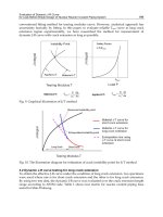
Table 7 summarizes the results of fracture mechanics tests of the studied steel in air at 290°C
performed in accordance with GOST 25.506-85. Fig.6 shows the J-R curve obtained. Fracture
toughness J
IC
determined from the J-R curve equals to J
IC
= 237 N/mm.
Resistance of 10GN2MFA-A
Low Alloy Steel to Stress Corrosion Cracking in High Temperature Water
281
No of test
specimen
a
o
[mm]
P
i
[N]
A
pi
[N.mm]
Δa
[mm]
J
i
[N/mm]
ZK1-40 26,0 74 671 211 395,1 1,68 629,8
ZK1-41 25,7 73 103 102 362,1 0,53 336,4
ZK1-42 25,6 75 662 144 246,0 0,78 447,2
ZK1-43 25,8 71 759 78 031,2 0,39 273,2
ZK1-44 25,8 72 069 172 442,1 1,28 517,2
ZK1-45 25,7 69 036 52 448,2 0,19 200,6
ZK1-47 25,9 71 008 242 460,2 1,80 700,7
ZK1-48 25,6 75 152 312 651,9 2,09 874,3
Table 7. Results of fracture mechanics tests in air at 290°C
Ji = 305,8
a + 175,8
0
200
400
600
800
1000
1200
0
0,5 1 1,5 2 2,5 3
a [мм
Ji [N
/
мм
Fig. 6. J-R curve of the studied steel at 290
o
C determined by multiple test specimen method
This value is in a very good agreement with J
IC
determined in air at 290°C for 10GN2MFA
steel used for the manufacture of the collector bodies of Temelín NPP steam generators
(Matocha,K., Wozniak,J., 1995).
Results of slow strain rate tests of round bar test specimens, made of 10GN2MFA-A steel,
in high temperature water environment performed in both laboratories are summarized in
table 8.
Nuclear Power – Control, Reliability and Human Factors
282
Test temperature
Initial concentration of
dissolved oxygen
CNIITMASH M&MR
Reduction of area [%] Reduction of area [%]
260°C
4,5 ppm
9,3 8,6
9,6 12,3
8,7 12,4
1,5 ppm
69,9 > 54,1
67,5 68,9
66,5
0,5 ppm
76,3 73,2
77,1 71,1
290°C (M&MR)
300°C (CNIITMASH)
1,5 ppm 75,2
4,5 ppm 74,8 77,0
Table 8. Results of slow strain rate tests of 10GN2MFA-A steel carried out in CNIITMAS
and in M&MR, Ltd.
Table 8 shows a very good agreement between the results obtained in both laboratories for
all initial concentrations of dissolved oxygen investigated. Fracture surfaces of the failured
test specimens were examined by scanning electron microscope JEOL JM-5510. Fracture
surfaces of the test specimens having low level of reduction of area showed the same
fractographic features formerly observed on fracture surfaces of 1CT tests specimens tested
in aerated distilled water (see Fig.7), (Matocha,K., Wozniak,J., 1995).
Fig. 7. Morphology of the fracture surface of the test specimen tested in water environment
at 260
o
C (initial O
2
= 4, 5 ppm, R.A. = 12, 4%)
Resistance of 10GN2MFA-A
Low Alloy Steel to Stress Corrosion Cracking in High Temperature Water
283
Metallographic evaluation of test specimen cross sections showed that the transverse
microcracks observed on the fracture surface (see Fig.7) were initiated in the process zone
ahead of the growing crack and probably contributed to the increase of crack growth rate
(see Fig. 8), (Matocha,K., Rožnovská,G. & Hanus,V, 2007). In all cases the stress corrosion
cracks were initiated from the pits (see Fig.9).
Fig. 8. The occurrence of transverse microcracks on fracture surface and in process zone of
the growing crack (Matocha,K., Rožnovská,G. & Hanus,V, 2007).
Fig. 9. Fracture surface of the test specimen tested in water environment at 260°C
(initial O
2
= 4,5 ppm, R.A. = 12,4%)
Table 9 shows the comparison of the slow strain rate tests results obtained in CNIITMASH
using round bar specimens manufactured of 10GN2MFA-A and 10GN2MFA-S steels at a
strain rate 1,4.10
-7
s
-1
.