Ferroelectrics Characterization and Modeling Part 10 pot
Bạn đang xem bản rút gọn của tài liệu. Xem và tải ngay bản đầy đủ của tài liệu tại đây (1.22 MB, 35 trang )
For many years, heterojunctions have been one of the fundamental research areas of
solid state science. The interest in this topic is stimulated by the wide applications
of heterojunction in microelectronics. Devices such as heterojunction bipolar transistors,
quantum well lasers and heterojunction field effect transistors (FET), already have a significant
technological impact. The semiconductor-ferroelectric heterostructures have attracted much
attention due to their large potential for electronic and optoelectronic device applications
(Lorentz et al., 2007; Losego et al., 2009; Mbenkum et al., 2005; Voora et al., 2009; 2010). The
ferroelectric constituent possesses switchable dielectric p olarization, which can be exploited
for modificating the electronic and optical properties of a semiconductor heterostructure.
Hysteresis properties of the ferroelectric polarization allows for bistable interface polarization
configuration and potentially for bistable heterostructure o peration modes. Therefore, the
The heterostructures of wurtzite semiconductors and perovskite ferroelectric oxide integrate
the rich properties of perovskites together with the superior optical and electronic properties
of wurtzites, thus providing a powerful method of new multifunctional devices. The electrical
and optical properties of the heterostructures are strongly influenced by the interface band
offset, which dictates the degree of charge carrier separation and localization. It is very
important to determine the valence band offset (VBO) of semiconductor/ferroelectric oxides
in order to understand the electrical and optical properties of the heterostructures and to
design novel devices. In this chapter, by using X-ray photoelectron spectroscopy (XPS),
we determine the VBO as well as the conduction band offset (CBO) values of the typical
semiconductor/ferroelectric oxide heterojunctions, such as ZnO/SrTiO
3
,ZnO/BaTiO
3
,
InN/SrTiO
3
and InN/BaTiO
3
, that are grown by metal-organic chemical vapor deposition.
Based on the values of VBO and CBO, it has been found that type-II band alignments
form at the ZnO/SrTiO
3
and ZnO/BaTiO
3
interfaces, while type-I band alignments form at
InN/SrTiO
3
and InN/BaTiO
3
interfaces.
1. Introduction
0
Valence Band Offsets of ZnO/SrTiO
3
, ZnO/BaTiO
3
,
InN/SrTiO
3
, and InN/BaTiO
3
Heterojunctions
Measured by X-ray Photoelectron Spectroscopy
Caihong Jia
1,2
, Yonghai Chen
1
, Xianglin Liu
1
, Shaoyan Yang
1
and ZhanguoWang
1
1
Key Laboratory of Semiconductor Material Science, Institute of Semiconductors,
Chinese Academy of Science, Beijing
2
Key Laboratory of PhotovoltaicMaterials of Henan Province and School of Physics
Electronics, Henan University, Kaifeng
China
Measured by X-Ray Photoelectron Spectroscopy
16
2 Will-be-set-by-IN-TECH
heterostructures of wurtzite semiconductors and perovskite ferroelectric oxides integrate the
rich properties of perovskites together with the superior optical and electronic properties of
wurtzites, providing a powerful method of new multifunctional devices (Peruzzi et al., 2004;
Wei et al., 2007; Wu et al., 2008). It is well known that the electrical and optical properties of
the heterostructures are strongly influenced by the interface band offset, which determines
the barrier for hole or electron transport across the interface, and acts as a boundary condition
in calculating the band bending and interface electrostatics. Therefore, it is very important
to determine the valence band offset (VBO) of semiconductor/ferroelectric oxides in order to
understand the electrical and optical properties of the heterostructures and to design novel
devices.
Zinc oxide (ZnO) is a direct wide bandgap semiconductor with large exciton binding energy
(60 meV) at room temperature, which makes it promising in the field of low threshold
current, short-wavelength light-emitting diodes (LED) and laser diodes (Ozgur et al., 2005).
It also has a growing application in microelectronics such as thin film transistors (TFT) and
transparent conductive electrodes because of high transparency and large mobility. Indium
nitride (InN), with a narrow direct band gap and a high mobility, is attractive for the near
infrared light emission and high-speed/high-frequency electronic devices (Losurdo et al.,
2007; Takahashi et al., 2004). Generally, ZnO and InN films are grown on foreign substrates
such as c-plane and r-plane sapphire, SiC (Losurdo et al., 2007; Song et al., 2008), (111)
Si and GaAs (Kryliouk et al., 2007; Murakami et al., 2008). SrTiO
3
(STO) single crystal is
widely used as a substrate for growing ferroelectric, magnetic and superconductor thin
films. Meanwhile, STO is one of the important oxide materials from both fundamental
physics viewpoint and potential device applications (Yasuda et al., 2008). The electron density
and hence conductivity of STO can be controlled by chemical substitution or annealing in
a reducing atmosphere. Furthermore, a high-density, two-dimensional electron (hole) gas
will lead to tailorable current-voltage characteristics a t interfaces between ZnO or InN and
STO (Singh et al., 2003). In addition, the lattice polarity of ZnO and InN (anion-polarity or
cation-polarity) is expected to be controlled by the substrate polarity considering the atomic
configuration of STO surface, which is also important to obtain a high-quality ZnO or InN
epitaxial layer (Murakami et al., 2008). Thus, it is interesting to grow high quality wurtzite
ZnO and InN films on perovskite STO substrates, and it is useful to determine the valence
band offset (VBO) of these heterojunctions.
The heterojunction of semiconductor-ZnO or InN/ferroelectric-BaTiO
3
(BTO) provides an
interesting optoelectronic a pplication due to the anticipated strong polarization coupling
between the fixed semiconductor dipoleand the switchable ferroelectricdipole (Lorentz et al.,
2007; Losego et al., 2009; Mbenkum et al., 2005; Voora et al., 2009; 2010). ZnO TFT, highly
attractive for display applications due to transparency in the visible and low growth
temperatures, are limited by large threshold and operating voltages (Kim et al., 2005). BTO,
as a remarkable ferroelectric material with a high r elative p ermittivity, can be used as the
gate dielectric to reduce the operating voltages of TFT for portable applications (Kang et al.,
2007; Siddiqui et al., 2006), and as an attractive candidate as an epitaxial gate oxide for
field effect transistor. In addition, the free carrier concentration in the ZnO channe l can be
controlled by the ferroelectric polarization of BTO dielectric in the ZnO/BTO heterostructure
field-effect-transistors, thus demonstrating nonvolatile memory elements (Brandt et al., 2009).
In order to fully exploit the advantages of semiconductor-ferroelectric heterostructures, other
combinations such as InN/BTO should be explored. As a remarkable ferroelectric material
with a high relative permittivity, BTO can be used as a gate dielectric for InN based field
306
Ferroelectrics - Characterization and Modeling
Valence Band Offsets of ZnO/SrTiO
3
, ZnO/BaTiO
3
,InN/SrTiO
3
, and InN/BaTiO
3
Heterojunctions Measured by X-ray Photoelectron Spectroscopy 3
effect transistor. More importantly, InN/BTO heterojunction is promising for fabricating
optical and electrical devices since oxidation treatment is found to reduce the surface electron
accumulation of InN film (Cimalla et al., 2007). Therefore, it is important to determine
the VBO of these semiconductor/ferroelectric heterojunctions to design and analyze the
performance of devices.
In this chapter, we will first present several methods to determine the energy discontinuities.
Then, by using x-ray photoelectron spectroscopy (XPS), we determine the VBO as well as
the conduction band offset (CBO) values of the typical semiconductor/ferroelectric oxide
heterojunctions, such as ZnO/STO, ZnO/BTO, InN/STO, and InN/BTO, that are grown by
metal-organic chemical vapor deposition. Based on the values of VBO and CBO, it has been
found that type-II band alignments form at the ZnO/STO and ZnO/BTO interfaces, while
type-I band alignments form at the InN/STO and InN/BTO interfaces.
2. Measurement methods
The e nergy band edge discontinuities at heterostructures can be determined by applying a
large variety of experimental techniques, such as electrical transport measurements including
capacitance-voltage (C-V) and current-voltage (I-V), optical measurement, photoemission
measurement (Capasso et al., 1987). For many years, analysis of the capacitance-voltage
and current-voltage of heterojunctions have proven to be important probes for determining
the energy barriers of pn junction, Schottky barriers and heterojunctions. The energy
discontinuities can be determined by C-V measurement, since the C(V) function has the form
of:
C
=
2(
1
N
1
+
2
N
2
)
q
1
2
N
1
N
2
(V
D
−V)
−1/2
,(1)
where
1
and
2
are the dielectric constants of materials 1 and 2, N
1
and N
2
are the dopant
concentrations of m aterials 1 and 2, V
D
is the diffusion potential, while q is the electronic
charge. Therefore, the plot of C
−2
versus V gives a straight line, intercepting the V-axis
exactly a t V=V
D
. Based on this quantity, the conduction band discontinuity energy, ΔE
c
,can
be obtained to be
ΔE
c
= qV
D
+ δ
2
−( E
g1
−δ
1
),(2)
for anisotype pN heterojunctions; and
ΔE
c
= qV
D
+ δ
2
−δ
1
,(3)
for isotype nN heterojunctions. Where δ
1
and δ
2
refer to the position of the Fermi energies
relative to the conduction band minimum (or valence band maximum) in n (or p)-type
materials 1 and 2, respectively. That is,
δ
i
= kT ln(
N
ci
N
i
), i = 1, 2. (4)
Here, kT is the Boltzmann energy at the temperature T, N
ci
is the effective conduction band
density of states,
N
c
=
2(2πm
∗
kT)
3
2
h
3
,(5)
307
Valence Band Offsets of ZnO/SrTiO
3
, ZnO/BaTiO
3
,
InN/SrTiO
3
, and InN/BaTiO
3
Heterojunctions Measured by X-Ray Photoelectron Spectroscopy
4 Will-be-set-by-IN-TECH
which is a function of the reduced effective mass of the electron (m
∗
) and of temperature (T).
Therefore, the difference in the Fermi energies between materials 1 and 2 can be simplified to
give
δ
2
−δ
1
= kT ln(
N
D1
N
D2
)+
3
2
kTl n
(
m
∗
2
m
∗
1
),(6)
for an nN heterojunction. Thus once the diffusion potential V
D
is determined, it is relatively
straightforward to obtain the conduction band discontinuity. Indeed, as can be seen from the
equation above, it is not necessary to have a highly precise measurement of any of the m aterial
parameters such as the bulk free carrier concentration or the effective density of states, since
ΔE
c
depends only logarithmically on these parameters. On the other hand, the dependence
of ΔE
c
on V
D
is linear, and, therefore, it is important that the measurement of the diffusion
potential be as accurate as possible.
The current density is given simply by
J
= A
∗
T
2
ex p(−
qφ
B
kT
),(7)
where φ
B
is the barrier height, from which the e nergy band offset can be determined. The
transport measurements have the advantage of being a relatively und erstanding means of
acquiring data using s imple structures, but the accuracy of these techniques has never been
considered to be particularly high, basically due to the existence of parasitic phenomena
giving rise to excess stray capacitances o r dark currents, which introduces variables cannot
be easily treated in the overall analysis and confuse the measurements.
The optical measurement techniques are based on the study of the optical properties of
alternating thin layers of two semiconductors. The quantized energy levels associated w ith
each well depend on the corresponding discontinuity, on the width of the well and on the
effective mass. The processes involving the localized quantum well states will introduce series
of peaks both in the absorption and photoluminescence spectra. From the position in energy
of the peaks in each series, it is possible to retrieve the parameters of the well and in particular
the value of ΔE
C
and ΔE
V
. However, this approach requires the fabrication of high-quality
multilayer structures with molecular beam epitaxy, and can only be applied to nearly ideal
interface with excellent crystal quality.
For x-ray photoelectron spectroscopy (XPS), it is well established that the kinetic energy,
E
K
, of electrons emitted from a semiconductor depends on the position of the Fermi level,
E
F
, within the semiconductor band gap. This aspect of XPS makes it possible to determine
E
F
relative to the valence band maximum, E
V
, i n the region of the semiconductor from
which the photoelectron originate. Therefore, besides analyzing the interface elemental and
chemical composition, XPS can also be used as a contactless nondestructive and direct access
to measure interface potential related quantities such as heterojunction band discontinuites.
This technique was pioneered by Grant ea al (Grant et al., 1978). Since the escape depths of
the respective photoelectrons are in the order of 2 nm only, one of the two semiconductors has
to be sufficiently thin. This condition may be easily met when heterostructures are grown by
molecular beam epitaxy (MBE) or metal-organic chemical vapor deposition (MOCVD). The
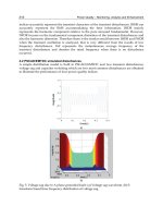
XPS method for determining VBO is explained by the schematic band diagram displayed in
Fig. 1, in which an idealized flat band was assumed. Based on the measured values of ΔE
CL
,
the core level to E
V
binding energy difference in bulk semiconductors A and B, (E
A
CL
-E
A
V
)and
308
Ferroelectrics - Characterization and Modeling
Valence Band Offsets of ZnO/SrTiO
3
, ZnO/BaTiO
3
,InN/SrTiO
3
, and InN/BaTiO
3
Heterojunctions Measured by X-ray Photoelectron Spectroscopy 5
(E
B
CL
-E
B
V
), respectively. By inspection of Fig. 1, it can be seen that
ΔE
V
(B − A )=(E
B
CL
− E
B
V
) −(E
A
CL
− E
A
V
)+ΔE
CL
(A − B).(8)
Thus, to apply XPS for ΔE
V
measurements, it is essential to determine the bulk semiconductor
material parameters (E
CL
-E
V
) for those semiconductors forming the heterojunctions. A
primary difficulty with measuring (E
CL
-E
V
) is the accurate determination of the E
V
position
in photoemission spectra. The most frequently employed method involves extrapolation of a
tangent line to the leading edge of the valence band spectrum to the energy axis, this intercept
is defined as E
V
. Substituting these values to Eq. 8 , the VBO of heterojunction A/B can be
obtained.
increasing E
B
BA
E
CL
B
E
c
A
E
v
A
E
CL
A
E
c
B
E
v
B
E
g
B
E
g
A
(E
CL
-E
v
)
A
(E
CL
-E
v
)
B
ǻE
c
ǻE
v
ǻE
CL
E
B
=0
E
F
Fig. 1. Schematic energy band diagram illustrating the measurement of VBO by XPS.
3. Experimental
Several samples, bulk commercial (001) STO, (111) ST O and (001) BTO substrates, thick
(several hundred nanometers) and thin (about 5 nm) ZnO and InN layers grown on the
commercial STO and BTO substrates were studied in this work. To get a clean interface,
the STO and BTO substrates were cleaned with organic solvents and rinsed with de-ionized
water sequentially before loading into the reactor. The thick and thin heterostructures of
ZnO/STO, ZnO/BTO, InN/STO and InN/BTO were deposited by MOCVD. More growth
condition details of the ZnO and InN layers can be found in our previous reports (Jia et al.,
2008; 2009a;b; 2010a;b; 2011; Li et al., 2011).
XPSs were performed on ThermoFisher ESCALAB 250, PHI Quantera SXM, and VG MKII
XPS instruments with AlKα (hν=1486.6 eV) as the x-ray radiation source, which had been
carefully calibrated on work function and Fermi energy level (E
F
). Becauseallthesamples
were exposed to air, there must be some impurities (e.g., oxygen and carbon) existing in the
sample surface, which may prevent the precise determination of the positions of the valence
band maximum (VBM). To reduce the undesirable effects of surface co ntamination, all the
samples were cleaned by Ar
+
bombardment at a low sputtering rate to avoid damage to the
samples. After the bombardment, peaks related to impurities were greatly reduced, and no
new peaks appeared. Because a large amount of electrons are excited and emitted from the
sample, the sample is always positively charged and the e lectric field caused by the charge can
affect the measured kinetic energy of photoelectron. Charge neutralization was performed
309
Valence Band Offsets of ZnO/SrTiO
3
, ZnO/BaTiO
3
,
InN/SrTiO
3
, and InN/BaTiO
3
Heterojunctions Measured by X-Ray Photoelectron Spectroscopy
6 Will-be-set-by-IN-TECH
with an electron flood gun and all XPS spectra were calibrated by t he C 1s p eak at 284.8 eV
from contamination to compensate the charge effect. Since only the relative energy position in
each sample is needed to determine the VBO, the absolute energy calibration for a sample
has no effect on the ultimate result. The surfaces of samples were examined initially by
low-resolution survey scans to determine which elements were present. Very high-resolution
spectra were acquired to determine the binding energy of core level (CL) and the valence
band maximum energy in the survey spectra. All the CL spectra were fitted to Voigt (mixed
Lorentz-Gaussian) line shape with a Shirley background. Since considerable acco rdance of the
fitted line to the original measured data has been obtained, the uncertainty of the CL position
should be less than 0.03 eV, as evaluated by numerous fittings with different parameters. The
VBM positions in the valence band (VB) spectra were determined by linear extrapolation of
the leading edge of the VB spectra recorded on bulk substrates and thick films to the base
lines in order to account for instrument resolution i nduced tail (Zhang et al., 2007), which
has already been widely used to determine the VBM of semiconductors. Evidently, the VBM
value i s sensitive to the choice of points o n the leading edge used to obtain the regression
line (Chambers et al., 2001). Thus, several different sets of points were selected over the linear
region of the leading edge to perform regressions, and the uncertainty of VBO is found to be
less than 0.06 eV in the present work.
4. VBO for ZnO/STO heterojunction
Figure 2 (a) shows the x-ray θ-2θ diffraction patterns of thick ZnO films on (111) STO
substrates. The diffractogram indicates only a single phase ZnO with a hexagonal wurtzite
structure. Only peaks of ZnO (0002) and (0004) reflection and no other ZnO related peaks are
observed, implying a complete c-axis oriented growth of the ZnO layer. The highly oriented
ZnO films on STO substrate strongly suggest that the nucleation and crystal growth is initiated
near the substrate surface. The full width at half maximum (FWHM) of symmetric (0002) scan
is about 0.85
◦
along ω-axis, as shown in the inset of Fig. 2(a). X-ray off-axis φ scans are
performed to identify the in-plane orientation relationships between the film and substrate.
The number of peaks in a φ scan corresponds to the number of planes for a particular family
that possesses t he same angle with the film surface. Figure 2 (b) shows the results of x-ray
φ scans performed using the
{1122} reflection of ZnO (2θ=67.95
◦
, χ=58.03
◦
)andthe{110}
reflection of STO (2θ=32.4
◦
, χ=35.26
◦
). Only six peaks separated by 60
◦
are observed f or the
ZnO
{112} family, which has six crystal planes with the same angle with the growth plane
(χ =58.03
◦
), as shown in Fig. 2 (b), indicating a single domain. From the relative position
of ZnO
{112} and STO {110} families, the in-plane relationships can be determined to be
[11
20]ZnO[011]STO. The atomic arrangement in the (0001) basal plane of ZnO is shown
in Fig. 2 (c). The growth in this direction shows a large lattice mismatch of about 17.7%
(
2a
ZnO
−
√
2a
STO
√
2a
STO
×100%) along the direction of <1120>
ZnO
, although it shows a much smaller
lattice mismatch of 1.91% (
√
3a
ZnO
−
√
2a
STO
√
2a
STO
×100%) along the direction of <1100>
ZnO
when
ZnO rotated 30
◦
in plane.
For ZnO/STO heterojunction, the VBO (ΔE
V
) can be calculated from the formula
ΔE
V
= ΔE
CL
+(E
ZnO
Zn2p
− E
ZnO
VBM
) −(E
STO
Ti2p
− E
STO
VBM
),(9)
310
Ferroelectrics - Characterization and Modeling
Valence Band Offsets of ZnO/SrTiO
3
, ZnO/BaTiO
3
,InN/SrTiO
3
, and InN/BaTiO
3
Heterojunctions Measured by X-ray Photoelectron Spectroscopy 7
20 30 40 50 60 70 80
-3 -2 -1 0 1 2 3
Intensity (arb. units.)
Z (deg.)
STO(111)
ZnO(004)
ZnO(002)
Intensity (arb. units.)
2T (deg.)
0 50 100 150 200 250 300 350
STO{110} (2T=32.40
o
F=35.26
o
)
ZnO{112} (2
T=67.95
o
F=58.03
o
)
Intensity (arb. units.)
I (deg.)
2 a
STO
a
ZnO
[1100]
[211
]
[011]
(111)STO
[112
0]
(0001)ZnO
(c)
(a) (b)
Fig. 2. X-ray θ-2θ (a), ω (inset of (a)), and φ (b) scans and atomic arrangement (c) of ZnO films
on (111) STO substrate.
where ΔE
CL
=(E
ZnO/STO
Ti2p
-E
ZnO/STO
Zn2p
) is the energy difference between Zn 2p and Ti 2p CLs
measured in the thin ZnO/STO heterojunction sample, a nd (E
STO
Ti2p
-E
STO
VBM
)and(E
ZnO
Zn2p
-E
ZnO
VBM
)
are the VBM energies with reference to the CL positions of bulk STO and thick ZnO film,
respectively, w hich are obtained by XPS measurement from the respective STO substrate and
thick ZnO film.
Figure 3 shows the XPS Ti 2p and Zn 2p CL narrow scans and the valence band spectra
from the STO substrate and the thick ZnO/STO samples, respectively. As shown in Fig.
3(a), the Zn 2p CL peak locates a t 1021.69
±0.03 eV. Fig. 3(e) s hows the VB spectra of the
thick ZnO sample, and the VBM position is determined to be 1.06
±0.06 eV by a linear fitting
depicted above. As a result, the energy difference of Zn 2p to ZnO VBM (E
ZnO
Zn2p
-E
ZnO
VBM
)can
be determined to be 1020.63
±0.03 eV. Using the same Voigt fitting and linear extrapolation
methods mentioned abo ve, the energy difference of T i2p to STO VBM (E
STO
Ti2p
-E
STO
VBM
)canbe
determined to be 457.32
±0.06 eV. The CL spectrum of Zn 2p and Ti 2p in thick ZnO film
and bulk STO are quite symmetric indicating the uniform bonding state and the only peaks
correspond to Zn-O and Ti-O bonds, respectively. The measurement of ΔE
CL
for the Ti 2p and
Zn 2p CLs recorded in the thin ZnO/STO junction is illustrated in Fig. 3(c) and (d). After
substraction of the background, the spectra of Ti 2p and Zn 2p CLs were well Voigt fitted and
the energy difference of Ti 2p and Zn 2p CLs (ΔE
CL
) can be determined to be 562.69±0.03
eV. It is noteworthy that the Ti 2p peak is not symmetric and consists of two components by
careful Voigt fitting. The prominent one located at 459.22 eV is attributed to the Ti emitters
within the ST O substrate which have six bonds to oxygen atoms, and the other one shifting
by
∼2 eV to a lower binding energy indicates the presence of an interfacial oxide layer. This
phenomenon is similar to that observed in the interface of LaAlO
3
/SrTiO
3
, and the shoulder
at lower binding energy is attributed to TiO
x
suboxides, which is expected on account of the
TiO
x
-terminated STO initial surface (Kazzi et al., 2006). The fair double-peak fitting shown
311
Valence Band Offsets of ZnO/SrTiO
3
, ZnO/BaTiO
3
,
InN/SrTiO
3
, and InN/BaTiO
3
Heterojunctions Measured by X-Ray Photoelectron Spectroscopy
8 Will-be-set-by-IN-TECH
in Fig. 3(d) confirms the presence of TiO
x
suboxides. Substituting the above (E
STO
Ti2p
-E
STO
VBM
),
(E
ZnO
Zn2p
-E
ZnO
VBM
)andΔE
CL
into Eq. 9, the resulting VBO value is calculated to be 0.62±0.09 eV.
1010 1015 1020 1025 1030
(a) ZnO: Zn2p
1021.69 eV
-4 -2 0 2 4 6
1.06 eV
(e) ZnO: VBM
-4-202468
0.98 eV
(f) STO: VBM
445 450 455 460 465 470
(b) STO: Ti2p
458.30 eV
1010 1015 1020 1025 1030
(c) ZnO/STO: Zn2p
1021.91 eV
445 450 455 460 465 470
(d) ZnO/STO: Ti2p
459.22 eV
Binding energy (eV)
Intensit
y(
arb. units
)
Fig. 3. Zn 2p spectra recorded on ZnO (a) and ZnO/STO (c), Ti 2p spectra on STO (b) and
ZnO/STO (d), and VB spectra for ZnO (e) and STO (f). All peaks have been fitted to Voigt
line shapes using Shirley background, and the VBM values are determined by linear
extrapolation of the leading edge to the base line. The errors in the peak positions and VBM
are
±0.03 and ±0.06 eV, respectively.
The reliability of the measured result is analyzed by considering several possible factors that
could impact the experiment results. The lattice mismatch between ZnO and STO is about
∼17.7%, which will induce a much smaller critical thickness than 5-10 nm, compared with
the lattice mismatch of BaTiO
3
grown on STO (2.2%) and a critical thickness of 5-10 nm
(Sun et al., 2004). Meanwhile, the ZnO epitaxial layer grown on STO substrate by MOCVD is
characterized by columnar growth mode, which provides strain relief mechanism (Fan et al.,
2008). Thus, the ZnO overlayer in the heterojunction is almost completely strained and the
strain-induced piezoelectric field effect can also be neglected. In addition, the error induced
by band bending is checked to be much smaller than the average standard deviation of
±0.09
eV given above (Yang et al., 2009). Since the factors that can affect the ultimate result can be
excluded from the measured result, the experimental obtained VBO value is reliable.
To further confirm our result, it would be very useful to compare our experimental results
with a theoretical model proposed by M
¨
onch (Monch et al., 2005). The VBOs of ZnO
heterojunctions are predicted based on the difference of the respective interface-induced gap
312
Ferroelectrics - Characterization and Modeling
Valence Band Offsets of ZnO/SrTiO
3
, ZnO/BaTiO
3
,InN/SrTiO
3
, and InN/BaTiO
3
Heterojunctions Measured by X-ray Photoelectron Spectroscopy 9
states (IFIGS) branch-point energies and electric dipole terms. That is
ΔE
V
= E
vl
(Γ) − E
vr
(Γ)=φ
p
bpr
−φ
p
bpl
+ D
X
(X
sr
− X
sl
), (10)
where the p-type branch-point energy φ
p
bp
(Γ)=E
bp
− E
V
(Γ) is the energy distance from the
valence band maximum to the branch point of the IFIGS and X
s
is the electronegativity of the
respective semiconductor. The subscripts r and l stand for the right and left side, respectively,
of the heterostructure. The dipole parameter D
X
is determined by the density of states and
extension of the IFIGS at their branch point. This dipole term can also be neglected, just
like the common semiconductor heterojunctions, since the electronegativities of the ato ms
constituting ZnO/STO heterojunction differ by up to 10% only. Through analysis of the VBO
values reported for ZnO heterostructure (Monch et al., 2005), the dependence of VBO on the
p-type branch-point energy is obtained to be
ΔE
V
= ϕ
vbo
[φ
p
bp
(ZnO) −φ
p
bp
(semi)]. (11)
With the p-type branch-point energies of ZnO (3.04 eV) (Monch et al., 2005) and STO (2.5
eV) (Monch et al., 2004), and the slope parameters ϕ
vbo
for insulator heterostructures of
1.14
∼1.23, a V BO of 0.64±0.21 eV would b e calculated, which is in good agreement with
the experimentally determined value of 0.62
±0.09 eV. It implies that the IFIGS theory is not
only widely used to the group-IV elemental semiconductors, SiC, and the III-V, II-VI, and
I-III-VI
2
compound semiconductors and their alloys (Monch et al., 2005), but also applicable t o
the semiconductor/insulator heterostructures. In addition, the resulting ΔE
V
is a sufficiently
large value for device applications in which strong carrier confinement is needed, such as
light emitters or he terostructure field effect transistors. For instance, the valence band offset
in the Zn
0.95
Cd
0.05
O/ZnO system is only 0.17 eV (Chen et al., 2005), which is less than that of
ZnO/STO.
Finally, the CBO (ΔE
C
) can be estimated by the formula ΔE
C
=ΔE
V
+E
ZnO
g
-E
STO
g
.By
substituting the band gap values (E
ZnO
g
=3.37 eV (Su et al., 2008) and E
STO
g
=3.2 eV (Baer et al.,
1967)), ΔE
C
is calculated to be 0.79±0.09 eV. It would be interesting to compare
our experimental values with the electrical transport results by Wu et al (Wu et al.,
2008). They have investigated the temperature d ependent current-voltage characteristic of
ZnO/Nb:SrTiO
3
junction, and found that the effective barrier height (φ
eff
)is0.73eV,which
is directly considered to be the CBO in n-N heterojunctions (Alivov et al., 2006). It can be seen
that the effective barrier height in Wu’s work is consistent with our CBO value. Accordingly,
a type-II band alignment forms at the heterojunction interface, in which the conduction and
valence bands of the ZnO film are concomitantly higher than those of the STO substrate, as
shown in Fig. 4.
5. VBO for ZnO/BTO heterojunction
In x-ray θ-2θ diffraction measurements, as shown in Fig. 5 (a), the ZnO/BTO sample presented
the only peak of ZnO (0002) reflection and no other ZnO related peaks were observed,
implying a complete c-axis oriented g rowth of the ZnO layer. From the pole figure of ZnO
{1011} family, shown in Fig. 5 (b), twelve peaks separated by 30
◦
are present, although ZnO
has a sixfold symmetry about the [0001] axis, indicating that the ZnO film is twinned in the
growth plane by a 30
◦
in-plane rotation. The relative intensities of the two sets of peaks is
313
Valence Band Offsets of ZnO/SrTiO
3
, ZnO/BaTiO
3
,
InN/SrTiO
3
, and InN/BaTiO
3
Heterojunctions Measured by X-Ray Photoelectron Spectroscopy
10 Will-be-set-by-IN-TECH
STO ZnO
E
Ti2p
STO
E
c
ZnO
E
v
ZnO
E
Zn2p
ZnO
E
c
STO
E
v
STO
E
g
STO
=3.2 eV
E
g
ZnO
=3.37 eV
(E
Zn2p
-E
v
)
ZnO
=1020.63 eV
(E
Ti2p
-E
v
)
STO
=457.32 eV
ǻE
c
=0.79 eV
ǻE
v
=0.62 eV
ǻE
CL
=562.69 eV
Fig. 4. Energy band diagram of ZnO/STO heterojunction.
related to the proportion of the two domains, indicating that the two domains are almost
equal in amount.
10 20 30 40 50 60 70 80
BTO (200)
BTO (002)
BTO (100)
BTO (001)
ZnO (002)
Intensity (arb. units.)
2T (deg.)
(a) (b)
Fig. 5. X-ray θ-2θ diffraction pattern (a) and pole figure (b) of the thick ZnO films on BTO
substrates.
For ZnO/BTO heterojunction, the VBO (ΔE
V
) can be calculated from the formula
ΔE
V
= ΔE
CL
+(E
ZnO
Zn2p
− E
ZnO
VBM
) −(E
BTO
Ti2p
− E
BTO
VBM
), (12)
where ΔE
CL
=(E
ZnO/BTO
Ti2p
-E
ZnO/BTO
Zn2p
) is the energy difference between Zn 2p and Ti 2p CLs
measured in the thin ZnO/BTO heterojunction, while (E
BTO
Ti2p
-E
BTO
VBM
)and(E
ZnO
Zn2p
-E
ZnO
VBM
)arethe
VBM energies with reference to the CL positions of bulk BTO and thick ZnO film, respectively.
Figure 6 shows the XPS Ti 2p and Zn 2p CL narrow scans and the valence band spectra from
the bulk BTO, thick and thin ZnO/BTO samples, respectively. For the thick ZnO film, the Zn
2p CL peak l ocates at 1022.04
±0.03 eV, and the VBM position is determined to b e 2.44±0.06
eV by a linear fitting described above, as shown in Fig. 6(a) and (e). The energy difference
between Zn 2p and VBM of thi ck ZnO film (E
ZnO
Zn2p3
-E
ZnO
VBM
) is deduced to be 1019.60±0.09
eV, which is well consistent with our previous reports (Zhang et al., 2007). It can also be
clearly seen from Fig. 6 that the CL spectra of Zn 2p and Ti 2p in the thick ZnO film and
thin ZnO/BTO heterojunction are quite symmetric, indicating a uniform bonding state and
314
Ferroelectrics - Characterization and Modeling
Valence Band Offsets of ZnO/SrTiO
3
, ZnO/BaTiO
3
,InN/SrTiO
3
, and InN/BaTiO
3
Heterojunctions Measured by X-ray Photoelectron Spectroscopy 11
-202468
2.44 eV
(e) ZnO: VBM
-202468
1.49 eV
(f) BTO: VBM
455 460 465
457.12 eV
(b) BTO: Ti 2p
1015102010251030
(a) ZnO: Zn 2p
1022.04 eV
1015102010251030
(c) ZnO/BTO: Zn 2p
1021.17 eV
455 460 465
457.68 eV
(d) ZnO/BTO: Ti 2p
Binding energy (eV)
Intensity (arb. units)
Fig. 6. Zn 2p spectra recorded on ZnO (a) and ZnO/BTO (c), T i 2p spectra on BTO (b) and
ZnO/BTO (d), and VB spectra for ZnO (e) and BTO (f). All peaks have been fitted to Voigt
line shapes using Shirley background, and the VBM values are determined by linear
extrapolation of the leading edge to the base line. The errors in the peak positions and VBM
are
±0.03 and ±0.06 eV, respectively.
BTO ZnO
E
Ti2p
BTO
E
c
ZnO
E
v
ZnO
E
Zn2p
ZnO
E
c
BTO
E
v
BTO
E
g
BTO
=3.1 eV
E
g
ZnO
=3.37 eV
(E
Zn2p
-E
v
)
ZnO
=1019.60 eV
(E
Ti2p
-E
v
)
BTO
=455.63 eV
ǻE
c
=0.75 eV
ǻE
v
=0.48 eV
ǻE
CL
=563.49 eV
Fig. 7. Energy band diagram of ZnO/BTO heterojunction.
the only peaks correspond to Zn-O and Ti-O bonds, respectively. However, the Ti 2p peak
in the bulk BTO is not symmetric and consists of two components by careful Voigt fitting.
The prominent one located at 457.12
±0.03 eV is attributed t o the Ti emitters within the BTO
substrate, which have six bonds to oxygen atoms. The other one shifting by
∼2eVtoalower
315
Valence Band Offsets of ZnO/SrTiO
3
, ZnO/BaTiO
3
,
InN/SrTiO
3
, and InN/BaTiO
3
Heterojunctions Measured by X-Ray Photoelectron Spectroscopy
12 Will-be-set-by-IN-TECH
binding energy is attributed t o TiO
x
suboxides on account of the TiO-terminated BTO initial
surface (Kazzi et al., 2006). It is interesting that the Ti 2p peaks transform from asymmetry
in bulk B T O to symmetry in the thin ZnO/BTO sample, implying that the T iO
x
suboxides
in the BTO surface is oxidized completely to the highest valence of Ti
4+
.TheVBMvalueof
bulk BTO is determined to be 1.49
±0.06 eV using the linear method. The Fermi level of an
insulator is expected to be located in the m iddle of the forbidden energy gap, so the VBM
will be one-half of the band gap of insulators (Yo u et al., 2009). For B TO, the VBM should
be 1.55 eV calculated from the band g ap of 3.1 eV (Boggess et al., 1990), which is in good
agreement w ith the measured value (1.49
±0.06 eV) in the present work. Using the same fitting
methods mentioned above, the energy values of CL for the thin ZnO/BTO heterojunction can
be determined, as shown in Fig. 6. Substituting the above values into Eq. 12, the resulting
VBO value is calculated to be 0.48
±0.09 eV.
A small lattice mismatch is present between the BTO[0
11] direction and the hexagonal
apothem of ZnO, which is only about 0.8% (
√
3a
ZnO
−
√
2a
BTO
√
2a
BTO
×100%) (Wei et al., 2007). This
lattice mismatch is so small that the strain-induced piezoelectric field effect can be neglected
in this work (Su et al., 2008). In ZnO/MgO heterostructure, the 8.3% mismatch brings a shift
of 0.22 eV on VBO (Li et al., 2008). By linear extrapolation method, the strain induced shift in
ZnO/BTO is less than 0.02 eV, which is much smaller than the aforementioned deviation of
0.09 eV. The error induced by band bending is checked to be much smaller than the average
standard deviation of 0.09 eV given above (Yang et al., 2009). So the experimental obtained
VBO value is reliable.
To further confirm the reliability of the experimental values, it would be useful to compare
our VBO value with other results deduced by transitive property. For heterojunctions formed
between all pairs of three materials (A, B, and C), ΔE
V
(A-C) can be deduced from the
difference between ΔE
V
(A-B) and ΔE
V
(C-B) neglecting the interface effects (Foulon et al.,
1992). The reported VBO values for some heterojunctions are ΔE
V
(ZnO-STO)=0.62 eV
(Jia et al., 2009b), ΔE
V
(Si-STO)=2.38 or 2.64 eV, and ΔE
V
(Si-BTO)=2.35 or 2.66 eV (Amy et al.,
2004), respectively. Then the ΔE
V
(ZnO-BTO) is deduced to be 0.59, 0.64, 0.9 or 0.33 eV, which
is comparable to our measured val u e 0.48
±0.09 eV. Since the samples were prepared under
different growth conditions, the different interfaces are responsible for the difference between
our measured value and the results from the transitivity. In addition, t he resulting ΔE
V
is a
sufficiently large value for device applications which require strong carrier confinement, such
as light emitters or heterostructure field effect transistors (Chen et al., 2005).
Finally, the CBO (ΔE
C
) can be estimated by the formula ΔE
C
=ΔE
V
+E
ZnO
g
-E
BTO
g
.By
substituting the band gap values at room temperature (E
ZnO
g
=3.37 eV (Su et al., 2008) and
E
BTO
g
=3.1 eV (Boggess et al., 1990)), ΔE
C
is calculated to be 0.75±0.09 eV. Accordingly, atype-II
band alignment forms at the heterojunction interface, in w hich the conduction and valence
bands of the ZnO film are concomitantly higher than those of the BTO substrate, as shown in
Fig. 7.
6. VBO for InN/STO heterojunction
Figure 8 (a) shows the typical XRD θ-2θ patterns of InN thin fi lms deposited on (001) STO
substrates. InN crystals shows an intense diffraction line at 2θ=31.28
◦
assigned to the (0002)
diffraction of InN with hexagonal wurtzite structure, implying that the c-axis of InN films
is perpendicular to the substrate surface. Figure 8 (b) shows the results of x-ray off-axis
316
Ferroelectrics - Characterization and Modeling
Valence Band Offsets of ZnO/SrTiO
3
, ZnO/BaTiO
3
,InN/SrTiO
3
, and InN/BaTiO
3
Heterojunctions Measured by X-ray Photoelectron Spectroscopy 13
φ scans performed using the {1011} reflection of InN (2θ=33.49
◦
, χ=61.86
◦
)andthe{111}
reflection of STO (2θ=39.96
◦
, χ=54.74
◦
) to determine the in-plane orientation of the InN film
relative to STO. Although InN has a sixfold symmetry about the [0001] axis, the presence of
twelve peaks separated by 30
◦
for {1122} reflections indicates that the InN films is twinned
in the growth plane by a 30
◦
in-plane rotation. The relative intensities of the two sets of
peaks is related to the proportion of the two domains, indicating almost the same amount
for the two domains. Comparing the locations in φ-space of the InN{10
11} with STO{111}
families, the two-dimensional epitaxial relationships for the two domains can be derived to
be [1
100]InN[110]STO f or one domain and [1120]InN[110]STO for the other. The atomic
arrangements for the two domains are illustrated in the schematic drawings of Fig. 8(c).
20 30 40 50 60 70 80
InN(112)
InN(004)
STO(003)
STO(002)
Intensity (arb. units.)
2T (deg.)
InN(002)
STO(001)
K
E
-150 -100 -50 0 50 100 150
STO{111} (2T=39.96
o
, F=54.74
o
)
InN{101} (2
T=33.49
o
, F=61.86
o
)
I(deg.)
(b)(a)
a
STO
a
InN
a
InN
(c)
Fig. 8. X-ray θ-2θ (a) and φ (b) scanning patterns, and atomic arrangement (c) of the thick InN
films on (001)STO substrates.
For InN/STO heterojunction, the VBO (ΔE
V
) can be calculated from the formula
ΔE
V
= ΔE
CL
+(E
InN
In3d
− E
InN
VBM
) −(E
STO
Ti2p
− E
STO
VBM
), (13)
where ΔE
CL
=(E
InN/STO
Ti2p
-E
InN/STO
In3d
) is the energy difference between In 3d and Ti 2p CLs
measured in the thin InN/STO heterojunction, while (E
STO
Ti2p
-E
STO
VBM
)and(E
InN
In3d
-E
InN
VBM
)arethe
VBM energies with reference to the CL positions of bulk STO and thick InN film, respectively.
Fig. 9 shows In 3d, Ti 2p CL narrow scans and valence band spectra recorded on thick InN,
bulk STO and thin InN/STO heterojunction samples, respectively. The In 3d spectra in thick
InN films include two peaks of 3d
5/2
(443.50±0.03 eV) a nd 3d
3/2
(451.09±0.03 eV), whi ch
are separated by t he spin-orbit interaction with a splitting energy of around 7.57 eV. Both
peaks are found out to c onsist of two components by careful Voigt fitting. The first In 3d
5/2
component located at 443.50±0.03 eV is attributed to the In-N bonding, and the second, at
444.52
±0.03 eV, is identified to be due to surface contamination. This two-peak profile of the
In 3d
5/2
spectra i n InN is ty pical and have been demonstrated by o ther researchers (King et al.,
2008; Piper et al., 2005; Yang et al., 2009). Comparison of their binding energy separation with
previous re sults, we suggest that the second peak at 444.52
±0.03 eV to the In-O bonding is due
to contamination by oxygen during the growth process. The ratio of In-N peak intensity to
317
Valence Band Offsets of ZnO/SrTiO
3
, ZnO/BaTiO
3
,
InN/SrTiO
3
, and InN/BaTiO
3
Heterojunctions Measured by X-Ray Photoelectron Spectroscopy
14 Will-be-set-by-IN-TECH
-2 0 2 4 6 8
0.45 eV
(e) InN: VBM
-20246810
(f) STO: VBM
1.91 eV
440 445 450 455
(a) InN: In3d
443.50 eV
455 460 465
(b) STO: Ti 2p
458.32 eV
440 445 450 455
(c) InN/STO: In 3d
443.68 eV
455 460 465
(d) InN/STO: Ti 2p
458.17 eV
Binding energy (eV)
Intensit
y(
arb. units
)
Fig. 9. In 3d spectra recorded on InN (a) and InN/STO (c), Ti 2p spectra on STO (b) and
InN/STO (d), and VB spectra for InN (e) and STO (f). All peaks have been fitted to Voigt line
shapes using Shirley background, and the VBM values are determined by linear
extrapolation of the leading edge to the base line. The errors in the peak positions and VBM
are
±0.03 and ±0.06 eV, respectively.
STO
InN
E
Ti2p
STO
E
c
InN
E
v
InN
E
In3d
InN
E
c
STO
E
v
STO
E
g
STO
=3.2 eV
E
g
InN
=0.7 eV
(E
In3d
-E
v
)
InN
=443.05 eV
(E
Ti2p
-E
v
)
STO
=456.41 eV
ǻE
c
=1.37 eV
ǻE
v
=1.13 eV
ǻE
CL
=14.49 eV
Fig. 10. Energy band diagram of InN/STO heterojunction.
the oxygen related peaks indicates that only a small quantity o f oxygen contamination exists
in our samples. Both the Ti 2p spectra in bulk STO and thin InN/STO heterojunction are
quite symmetric, indicating a uniform bonding state. Using the linear extrapolation method
mentioned above, the VBM of InN and STO are 0.45
±0.06 eV and 1.91±0.06 eV respectively.
318
Ferroelectrics - Characterization and Modeling
Valence Band Offsets of ZnO/SrTiO
3
, ZnO/BaTiO
3
,InN/SrTiO
3
, and InN/BaTiO
3
Heterojunctions Measured by X-ray Photoelectron Spectroscopy 15
Compared with the spectra recorded on the InN and STO samples, the In 3d core level shifts
to 443.68
±0.03 eV and Ti 2p shifts to 458.17±0.03 eV in thin InN/STO heterojunction. The
VBO value is calculated to be 1.13
±0.09 eV by substituting those values into Eq. 13.
Reliability of the analysis of the measured results is provided by considering possible factors
that could impact the experimental results. InN is a kind of piezoelectric crystal, so the strain
existing in the InN overlayer of the heterojunction will induce piezoelectric field and a ffect the
results. The lattice mismatch between InN and STO is larger than 9.8% (
√
3a
InN
−
√
2a
STO
√
2a
STO
×100%),
so the InN layer can be approximately treated as completely relaxed and this approximation
should not introduce much error in our result. In addition, the energy band bends downward
at the surface of InN film and there is an electron accumulation layer (Mahboob et al., 2004),
so the energy separation between VBM and Fermi level can be changed at the InN surface,
which could impact the measured VBO values of the heterojunctions. However, both the CL
emissions of In 3d and Ti2p at the InN/STO heterojunction are collected from the same surface
(InN surface), thus, the surface band bending effects can be canceled out for the measurement
of ΔE
CL
, as was the measurement of the band offset of the InN/AlN heterojunction by others
(King et al., 2007; Wu et al., 2006). Since the factors that can affect the results can be excluded
from the measured results, the experimental obtained VBO value is reliable.
Making use of the band gap of InN (0.7 eV) (Yang et al., 2009) and SrTiO
3
(3.2 eV) (Baer et al.,
1967), the CBO (ΔE
C
) is calculated to be 1 .37 eV and the ratio of ΔE
C
/ΔE
V
is close to 1:1. As
shown in Fig. 10, a type-I heterojunction is seen to be formed in the straddling configuration.
So STO can be utilized as the gate oxide for InN based metal-oxide semiconductor, the
gate leakage is expected to be negligible, which is different from the Si based devices
(Chambers et al., 2000).
7. VBO for InN/BTO heterojunction
10 20 30 40 50 60 70 80
Intensity (arb. units.)
InN (002)
BTO (200)
BTO (002)
BTO (100)
BTO (001)
2T (deg.)
Fig. 11. X-ray θ-2θ scanning patterns of the thick InN films on BTO substrates.
In x-ray θ-2θ diffraction measurements, as shown in Fig. 11, the thick InN/BTO sample
presented the only peak of InN (0002) reflection and no other InN related peaks were
observed, implying a complete c-axis oriented growth of the InN layer. For InN/BTO
heterojunction, the VBO (ΔE
V
) can be calculated from the formula
ΔE
V
= ΔE
CL
+(E
InN
In3d
− E
InN
VBM
) −(E
BTO
Ti2p
− E
BTO
VBM
), (14)
319
Valence Band Offsets of ZnO/SrTiO
3
, ZnO/BaTiO
3
,
InN/SrTiO
3
, and InN/BaTiO
3
Heterojunctions Measured by X-Ray Photoelectron Spectroscopy
16 Will-be-set-by-IN-TECH
-202468
1.49 eV
(f) BTO: VBM
455 460 465
457.12 eV
(b) BTO: Ti 2p
Binding energy (eV)
Intensity (arb. units)
455 460 465
458.43 eV
(d) InN/BTO: Ti 2p
-4-202468
0.24 eV
(e) InN: VBM
440 445 450 455
443.98 eV
(c) InN/BTO: In 3d
440 445 450 455
443.67 eV
(a) InN: In 3d
Fig. 12. In 3d spectra recorded on InN (a) and InN/BTO (c), Ti 2p spectra on BTO (b) and
InN/BTO (d), and VB spectra for InN (e) and BTO (f). All peaks have been fitted to Voigt line
shapes using Shirley background, and the VBM values are determined by linear
extrapolation of the leading edge to the base line. The errors in the peak positions and VBM
are
±0.03 and ±0.06 eV, respectively.
BTO InN
E
Ti2p
BTO
E
c
InN
E
v
InN
E
In3d
InN
E
c
BTO
E
v
BTO
E
g
BTO
=3.1 eV
E
g
InN
=0.7 eV
(E
In3d
-E
v
)
InN
=443.43 eV
(E
Ti2p
-E
v
)
BTO
=455.63 eV
ǻE
c
=0.15 eV
ǻE
v
=2.25 eV
ǻE
CL
=14.45 eV
Fig. 13. Energy band diagram of InN/BTO heterojunction.
where ΔE
CL
=(E
InN/BTO
Ti2p
-E
InN/BTO
In3d
) is the energy difference between In 3d and Ti 2p CLs
measured in the thin heterojunction InN/BTO, while (E
BTO
Ti2p
-E
BTO
VBM
)and(E
InN
In3d
-E
InN
VBM
)arethe
VBM energies with reference to the CL positions of bulk BTO and thick InN film, respectively.
320
Ferroelectrics - Characterization and Modeling
Valence Band Offsets of ZnO/SrTiO
3
, ZnO/BaTiO
3
,InN/SrTiO
3
, and InN/BaTiO
3
Heterojunctions Measured by X-ray Photoelectron Spectroscopy 17
Figure 12 shows the XPS Ti 2p and In 3d CL narrow scans and the valence band spectra
from the bulk BTO, thick InN and thin InN/BTO samples, respectively. For the In 3d spectra
of both the InN and thin InN/BTO samples, additional low intensity higher-binding-energy
components were required. These extra components are attributed to In-O bonding due to
oxide contamination when InN is present at the surface (Piper et al., 2005), as shown i n Fig.
12(a). In the thin InN/BT O sample shown in Fig. 12(c), they are attributed to In-O bonding
at the InN/BTO interfaces, and/or inelastic losses to free carriers in the InN layer (King et al.,
2008). The CL peak attributed to In-N bonding locates at 443.67
±0.03 eV and 443.98±0.03 eV
for thick InN and thin InN/BTO, respectively, as shown in Fig. 12(a) and (c). It is interesting
that the Ti 2p peaks transform from asymmetry in b ulk B T O to symmetry in the thin InN/B T O
sample, as observed in the thin ZnO/BTO heterostructure (Jia et al., 2010b). Using the same
fitting methods mentioned above, the VBM value for the bulk BTO and thick InN films can
be determined, as shown in Fig. 12 (e)and (f). Substituting the above values into Eq. 14, the
resulting VBO value is calculated to be 2.25
±0.09 eV.
The reliability of the measured result is analyzed by considering several possible factors that
could impact the experiment results. Both the CL emissions of In 3d and Ti 2p at the InN/BTO
heterojunction are collected from the same surface (InN surface), so the surface band bending
effects can be canceled out for the measurement of ΔE
CL
. Another factor which may affect
the precision of the VBO value is the strain-induced piezoelectric field in the overlayer
of the heterojunction (Martin et al., 1996). There is a large lattice mismatch of about 7.1%
(
√
3a
InN
−
√
2a
BTO
√
2a
BTO
×100%) between the hexagonal apothem of InN and the B T O[011] direction.
It is comparable with that of the InN/ZnO heterojunction (7.7%), and the InN thin film of 5
nm is approximately treated as completely relaxed (Zhang et al., 2007). So the strain-induced
piezoelectric field effect can be neglected in our experiment. Thus, the experimental obtained
VBO value is reliable.
To further confirm the reliability of the experimental values, it would be useful to compare our
VBO value with other results deduced by transitive property. The reported VBO values for
ZnO/BTO and InN/ZnO heterojunctions are ΔE
V
(ZnO-BTO)=0.48 eV (Jia et al., 2010b), and
ΔE
V
(InN-ZnO)=1.76 eV (Yang et al., 2009), respectively. Then the ΔE
V
(InN-BTO) is deduced
to be 2.24 eV, which is well consistent with our measured value 2.25
±0.09 eV.
Finally, the CBO (ΔE
C
) can be estimated by the formula ΔE
C
=E
BTO
g
-E
InN
g
-ΔE
V
. By substituting
the band gap values at room temperature (E
InN
g
=0.7 eV (Yang et al., 2009) and E
BTO
g
=3.1
eV (Boggess et al., 1990)), ΔE
C
is calculated to be 0.15±0.09 eV. Accordingly, a type-I band
alignment forms at the heterojunction interface, as shown in Fig. 13.
8. Conclusions
In summary, XPS was used to measure the VBO of the ZnO(or InN)/STO(or BTO)
heterojunctions. A type-II band al ignment with VBO o f 0.62
±0.09 eV and CBO of 0.79±0.09 eV
is obtained for ZnO/STO heterojunction. A type-II band alignment with VBO of 0.48
±0.09 eV
and CBO of 0.75
±0.09 eV is obtained for ZnO/BTO heterojunction. A type-I band alignment
with VBO of 1.13
±0.09 eV and CBO of 1.37±0.09 eV is obtained for InN/STO heterojunction.
A type-I band alignment with VBO of 2.25
±0.09 eV and CBO of 0.15±0.09 eV is obtained for
InN/BTO heterojuncion. The accurately determined result is important for the design and
application of these semiconductor/ferroelectric heterostructures based devices.
321
Valence Band Offsets of ZnO/SrTiO
3
, ZnO/BaTiO
3
,
InN/SrTiO
3
, and InN/BaTiO
3
Heterojunctions Measured by X-Ray Photoelectron Spectroscopy
18 Will-be-set-by-IN-TECH
9. Acknowledgements
This work was supported by the 973 program (2006CB604908, 2006CB921607), and the
National Natural Science Foundation of China (60625402, 60990313).
10. References
Alivov Y. I.; Xiao B.; Fan Q.; Morkoc H. & Johnstone D. (2006). Appl. Phys. Lett., Vol. 89, 152115
Amy F.; Wan A. S.; Kahn A.; Walker F. J. & Mckee R. A. (2004). J. Appl. Phys., Vol. 96, 1635
Baer W. S. (1967). J. Phys. Chem. Solids, Vol. 28, 677
Boggess T. F.; White J. O. & Valley G. C. (1990). J. Opt. Soc. Am. B., Vol. 7, 2255
Brandt M.; Frenzel H.; Hochmuth H.; Lorentz M.; Grundmann M. & Schubert J. (2009). J. Vac.
Sci. Technol. B, Vol. 27, 1789
Capasso F. & Margaritondo G. (1987). Heterojunction band discontinuities: Physics and device
applications, (115-377), Elsevier, 0444870601, North-Holland, Amsterdam Oxford
New York Tokyo
Chambers S. A.; Liang Y.; Yu Z.; Droopad R.; Ramdani J & Eisenbeiser (2000). Appl. Phys. Lett,
Vol. 77, 1662
Chambers S. A.; Liang Y.; Yu Z.; Droopad R. & Ramdani J (2001). J. Vac. Sci. Technol. A, Vol. 19,
934
ChenJ.J.;RenF.;LiY.J.;NortonD.P.;PeartonS.J.;OsinskyA.;DongJ.W.;ChowP.P.&
Weaver J. F. (2005). Appl. Phys. Lett., Vol. 87, 192106
CimallaV.;LebedevV.;WangC.Y.;AliM.;CkeG.E.;PolyakovV.M.;SchwierzF.;Ambacher
O.; Lu H. & Schaff W. J. (2007). Appl. Phys. Lett., Vol. 90, 152106
Fan H. B.; Sun, G. S.; Yang S. Y.; Zhang P. F.; Zhang R. Q.; Wei H. Y.; Jiao C. M.; Liu X. L.;
ChenY. H.; Zhu Q. S. & Wang Z. G. (2008). Appl. Phys. Lett., Vol. 92, 192107
Foulon Y. & Priester C. (1992). Phys.Rev.B, Vol. 45, 6259
Grant R. W.; Waldrop J. R. & Kraut E. A. (1978). Phys. Rev. Lett., Vol. 40, 656
Jia C. H.; Chen Y. H.; Liu G. H.; Liu X. L.; Yang S. Y. & Wang Z. G. (2008). J. Crystal Growth,
Vol. 311, 200-204
Jia C. H.; Chen Y. H.; L iu G. H.; Liu X. L.; Yang S. Y. & Wang Z. G. (2009). J. Phys. D: Appl.
Phys., Vol. 42, 015415
JiaC.H.;ChenY.H.;ZhouX.L.;YangA.L;ZhengG.L.;LiuX.L.;YangS.Y.&WangZ.G.
(2009). J. Phys. D: Appl. Phys., Vol. 42, 095305
Jia C. H.; Chen Y. H.; Zhou X. L.; Liu G. H.; Guo Y.; Liu X. L.; Yang S. Y. & Wang Z. G. (2010).
J. Crystal Growth, Vol. 312, 373-377
JiaC.H.;ChenY.H.;ZhouX.L.;YangA.L.;ZhengG.L.;LiuX.L.;YangS.Y.&WangZ.G.
(2010). Appl. Phys. A, Vol. 99, 511
Jia C. H.; Chen Y. H.; Liu X. L.; Yang S. Y. & Wang Z. G. (2011). Nano. Res. Lett,Vol.6,316
Kang K. T.; Lim M. H.; K im H. G.; Kim I. D. & Hong J . M. (2007). Appl. Phys. Lett., Vol. 90,
043502
Kazzi M. E.; Merckling C.; Delhaye G.; Arzel L.; Grenet G.; Bergignat E. & Hollinger G. (2006).
Mater. Sci. Semi. Proc., Vol. 9, 954
Kim D.; Choi Y. W. & Tuller H. L., (2005). Appl. Phys. Lett., Vol. 87, 042509
King P. D. C.; Veal T. D.; Jefferson P. H.; Mcconville C. F.; Wang T.; Parbrook P. J.; Lu H. & W.J.
Schaff (2007). Appl. Phys. Lett., Vol. 90, 132105
322
Ferroelectrics - Characterization and Modeling
Valence Band Offsets of ZnO/SrTiO
3
, ZnO/BaTiO
3
,InN/SrTiO
3
, and InN/BaTiO
3
Heterojunctions Measured by X-ray Photoelectron Spectroscopy 19
King P. D. C.; Veal T. D.; Lu H.; Hatfield S. A.; Schaff W. J. & Mcconville C.F. (2008). Surf. Sci.,
Vol. 602, 871
Kryliouk O.; Park H. J.; Won Y. S.; Anderson T.; Davydov A.; Levin I.; Kim J.H. & Freitas Jr. J.
A. (2007). Nanotechnology, Vol. 18, 135606
LiY.F.;YaoB.;LuY.M.;LiB.H.;GaiY.Q.;CongC.X.;ZhangZ.Z.;ZhaoD.X.;ZhangJ.Y.;
Shen D. Z. & Fan X. W. (2008). Appl. Phys. Lett., Vol. 92, 192116
Li Z. W.; Zhang B.; Wang J.; Liu J. M.; Liu X. L.; Yang S. Y.; Zhu Q. S. & Wang Z. G. (2011).
Nano. Res. Lett, Vol. 6, 193
Lorentz M.; Brandi M.; Schubert J.; H ochmuth H., Wenckstern H. v; Schubert M. &
Grundmann M. (2007). Procc. of SPIE, Vol. 6474, 64741S
LosurdoM.;GiangregorioM.M.;BrunoG.;KimT.H.;WuP.;ChoiS.;BrownA.;MasiaF.;
Capizzi M. & Polimeni A. (2007). Appl. Phys. Lett., Vol. 90, 011910
Losego M. D.; Kourkoutis L. F.; Mita S.; Craft H. S.; Muller D. A.; Collazo R.; Sitar Z. & Maria
J. P. (2009). J. Crystal Growth, Vol. 311, 1106
Mahboob I.; Veal T. D.; Mcconville C.F.; Lu H. & Schaff W. J. (2004). Phys. Rev. Lett.,Vol.92,
036804
Martin G.; Botchkarev A.; Rockett A. & Morkoc H. (1996). Appl. Phys. Lett., Vol. 68, 2541
Mbenkum B. N.; Ashkenov N.; Schubert M.; Lorentz M.; Hochmuth H.; Michel D.;
Grundmann M. & Wagner G. (2005). Appl. Phys. Lett., Vol. 86, 091904
M
¨
onch W. (2004). Electronic properties of Semiconductor Interfaces, Springer, Berlin, 176
M
¨
onch W. (2005). Appl. Phys. Lett., Vol. 86, 162101
Murakami H.; Eriguchi K. I.; Torri J. I.; Cho H. C.; Kumagai Y. & Koukitu A. (2008). J. Crystal
Growth, Vol. 310, 1602
Ozgur U.; Alivov Y. I.; Liu C.; Teke A.; Reshchikov M. A.; Dogan S.; Avrutin V.; Cho S. J. &
Morkoc H. (2005). J. Appl. Phys., Vol. 98, 041301
Peruzzi M.; P edarni J. D.; Bauerle D.; Schwinger W. & Schaffler F. (2004). Appl. Phys. A.,Vol.
79, 1873
Piper L. F. J.; Veal T. D.; Walker M.; Mahboob I.; Mcconville C.F., Lu H. & Schaff W. J. (2005). J.
Vac. Sci. Technol. A, Vol. 23, 617
Siddiqui J.; Cagin E.; D. Chen & Phillips J. D. (2006). Appl. Phys. Lett., Vol. 88, 212903
Singh M.; Wu Y. R. & J. Singh (2003). Solid State Electron., Vol. 47, 2155
Song D. Y.; Holtz M. E.; Chandolu A.; Bernussi A.; Nikishin S. A.; Holtz M. W. & Gherasoiu I.
(2008). Appl. Phys. Lett., Vol. 92, 121913
SuS.C.;LuY.M.;ZhangZ.Z.;ShanC.X.;LiB.H.;ShenD.Z.;YaoB.;ZhangJ.Y.;ZhaoD.X.
& Fan X. W. (2008). Appl. Phys. Lett., Vol. 93, 082108
Sun H. P.; Tian W.; Pan X. Q.; Haeni J. H. & Schlom D. G. (2004). Appl. Phys. Lett., Vol. 84, 3298
Takahashi N.; Niwa A. & Nakamura T. (2004). J. Phys. Chem. Solid., Vol. 65, 1259
Voora V. M.; Hofmann T.; Schubert M., Brandt M., Lorenz M., Grundmann M., Ashkenov N .
& Schubert M. (2009). Appl. Phys. Lett., Vol. 94, 142904
Voora V. M; Hofmann T.; Brandt M.; Lorenz M.; Grundmann M; Ashkenov N.; Schmidt H;
Ianno N. & Schubert M. (2010). Phys. Rev. B
, Vol. 81, No. 19, 195307
Wei X. H.; Li Y. R.; Jie W. J.; Tang J. L.; Zeng H. Z.; Huang W.; Zhang Y. & Zhu J. (2007). J. Phys.
D: Appl. Phys., Vol. 40, 7502
Wu C.L.; Shen C. H. & Gwo S. (2006).
Appl. Phys. Lett., Vol. 88, 032105
Wu Y. L.; Zhang L. W.; Xie G. L.; Zhu J. L. & Chen Y. H. (2008). Appl. Phys. Lett., Vol. 92, 012115
YangA.L.;SongH.P.;LiuX.L.;WeiH.Y.;GuoY.;ZhengG.L.;JiaoC.M.;YangS.Y.;ZhuQ.
S. & Wang Z. G. (2009). Appl. Phys. Lett., Vol. 94, 052101
323
Valence Band Offsets of ZnO/SrTiO
3
, ZnO/BaTiO
3
,
InN/SrTiO
3
, and InN/BaTiO
3
Heterojunctions Measured by X-Ray Photoelectron Spectroscopy
20 Will-be-set-by-IN-TECH
Yasuda H. & Kanemitsu Y. (2008). Phys.Rev.B., Vol. 77, 193202
YouJ.B.;ZhangX.W.;SongH.P.;YingJ.;GuoY.;YangA.L.;YinZ.G.;ChenN.F.&ZhuQ.
S. (2009). J. Appl. Phys., Vol. 106, 043709
Zhang R. Q.; Zhang P. F.; Kang T. T.; Fan H. B.; Liu X. L.; Yang S. Y.; Wei H. Y.; Zhu Q. S. &
Wang Z. G. (2007). Appl. Phys. Lett., Vol. 91, 162104
324
Ferroelectrics - Characterization and Modeling
Part 4
Modeling: Phenomenological Analysis
17
Self-Consistent Anharmonic
Theory and Its Application to BaTiO
3
Crystal
Yutaka Aikawa
Taiyo Yuden Co, Ltd.
Japan
1. Introduction
Because phase transition is important in solid state physics, numerous attempts have thus
far been made to study the nature of phase transitions in magnets, superconductors,
ferroelectrics, and so on. For ferroelectrics, both phenomenological and microscopic
approaches have been adopted to study phase transitions. Generally, it is considered that at
high temperatures, the general phenomenological theory and first-principles calculations
appears to be almost mutually exclusive.
It is well known that the phenomenological Landau theory of phase transitions can
provide a qualitatively correct interpretation of the soft mode of ferroelectrics at the Curie
temperature (L.D.Landau & E.M.Lifshitz, 1958); however, this theory cannot explain the
mechanism of ferroelectric phase transition. Furthermore, the coefficients of the expansion
terms of the Gibbs potential cannot be explained by the essential parameters derived by
first-principles calculations. The first principles calculations were performed to determine
the adiabatic potential surface of atoms, and the potential parameters were determined to
recreate the original adiabatic potential surface. This procedure ensures a highly
systematic study of ferroelectric properties without any reference to the experimental
values.
In order to study the phase transition, Gillis et al. discussed first the instability phenomena
in crystals, on the basis of a self-consistent Einstein model (N. S. Gills et al., 1968, 1971). In
this model each atom is assumed to perform harmonic oscillation with the frequency which
is self-consistently determined from the knowledge of interatomic potential in crystal and
the averaged motions of all atoms. The effect of anharmonicity comes in through the self-
consistent equations. T. Matsubara et al. applied this method to a simple one-dimensional
model to discuss anharmonic lattice vibration, which is enhanced on and near the surface
than in the interior (T. Matsubara & K. Kamiya,1977).
On the other hand, the combination of the results derived from first-principles calculations
with the effective Hamiltonian method implemented by means of a Monte Carlo simulation
(W. Zhong et al.,1995), seems to successfully explain the lattice strain change in BaTiO
3
at
high temperatures. However, the abovementioned approach cannot explain the behavior of
the dielectric property of materials at high temperatures during the phase transitions in the
soft mode.
Ferroelectrics - Characterization and Modeling
328
()
,VmH
nnn
nnnn
′
′
−+=
xxx
2
2
1
To discuss such high temperature transitions, K. Fujii et al. have proposed a self-consistent
anharmonic model (K. Fujii et al., 2001), and the author
has extended it to derive the
ferroelectric properties of BaTiO
3
(Y.AIkawa et al., 2007, 2009), in other words, it has been
shown that the ferroelectric properties of materials can be described by the interatomic
potential, which is derived from first-principles calculations. In the present study we
applied a theoretical method, namely, the self-consistent anharmonic theory, to study the
cubic-to-tetragonal phase transition in practical applications. The author shows that the
transition occurs in the soft mode, and that the relationship between the transition behavior
in the high temperature region and the essential parameters at absolute zero temperature
which can be derived using first-principles calculations.
In the previous study, the author introduces the anharmonicity not only into crystal
potential but also into trial one in order to extend the self-consistent Einstein model, and
succeeded to derive the soft mode frequency of BaTiO
3
crystal near the transition
temperature, and showed that the softening phenomena never take place when harmonic
oscillator is adopted as trial potential (Y. Aikawa & K. Fujii, 2010). Furthermore, it becomes
possible to explain the relation between the dielectric property in high temperature and
atomic potential at absolute zero temperature derived from first principles calculations
(Y.Aikawa et al., 2009 ), and also to explain the isotope effect (Y.Aikawa et al., 2010a),
surface effect (Y.Aikawa et al., 2010b; T. Hoshina et al., 2008), and so on.
2. Theoretical analysis
Landau constructed a phenomenological theory for the second order phase transition by
considering only the symmetry change of a system (L. D. Landau & E. M. Lifshitz, 1958).
Gibbs free energy is expanded by an order parameter
σ
in the vicinity of transition
temperature as
++−+=
42
0
σσ
A)TT(BGG
C
It is difficult to reflect microscopic information such as interactions between atoms in the
expansion coefficients A, B and the transition temperature T
C
.
K. Fujii et.al showed theoretically a softening mechanism from the variational principle at
finite temperature (K. Fujii et al., 2001, 2003). In that work, the coefficients of the second and
fourth order terms in a trial potential represented by an anharmonic oscillator system were
expressed by the characteristic constants of interatomic potentials in a crystal. The author
found that the temperature dependence of the coefficient of the second order term in the
trial potential shows the same behavior as the Landau expansion. The softening phenomena
are discussed on the basis of the temperature- and wave vector-dependence of the
expansion coefficient near the instability temperature, and the soft mode is identified by
introducing normal coordinates instead of direct atomic displacements.
It is considered a crystal system consisting of
N
atoms. Let
n
x
be coordinate of the n-th
atom whose mass is
n
m
. The Hamiltonian of this system is given by
(1)
where
V
are interatomic pair potentials. An interatomic distance between atoms
n
and
n
′
is given by