Integrated Waste Management Volume I Part 5 docx
Bạn đang xem bản rút gọn của tài liệu. Xem và tải ngay bản đầy đủ của tài liệu tại đây (912.4 KB, 35 trang )
Dry Digestion of Organic Residues
131
7. References
Amon, T.; Amon, B.; Kryvoruchko, V.; Machmüller, A.; Hopfner-Sixt, K.; Bodiroza, V.;
Hrbek, R.; Friedel, J.; Pötsch, E.; Wagentristl, H.; Schreiner, M. & Zollitsch, W.
(2007). Methane production through anaerobic digestion of various energy crops
grown in sustainable crop rotations. In: Bioresource Technology, Vol.98, pp. 3204-3212
Anand, V.; Chanakya, H.N. & Rajan, M.G.C. (1991). Solid phase fermentation of leaf biomass
to biogas. In: Resources, Conservation and Recycling, Vol.6, pp. 23-33
Andersson, J. & Björnsson, L. (2002). Evaluation of straw as a biofilm carrier in the
methanogenic stage of two-stage anaerobic digestion of crop residues. In:
Bioresource Technology, Vol.85, pp. 51-56
Banks, C.J.; Salter, A.M. & Chesshire, M. (2007). Potential of anaerobic digestion for
mitigation of greenhouse gas emissions and production of renewable energy from
agriculture: barriers and incentives to widespread adoption in Europe. In: Water
Science & Technology, Vol.55, No.10, pp. 165-173
Baserga, U.; Egger, K. & Wellinger, A. (1994). Biogas aus Festmist. Entwicklung einer
kontinuierlich betriebenen Biogasanlage zur Vergärung von strohreichem Mist.
FAT-Berichte Nr. 451. Tänikon: Eidgenössische Forschungsanstalt für
Agrarwirtschaft und Landtechnik (FAT) Tänikon, Switzerland
Bolzonella, D.; Innocenti, L.; Pavan, P.; Traverso, P. & Cecchi, F. (2003). Semi-dry
thermophilic anaerobic digestion of the organic fraction of municipal solid waste:
focusing on the start-up phase. In: Bioresource Technology, Vol.86, pp. 123-129
Borges Neto, M.R.; Carvalho, P.C.M.; Carioca, J.O.B. & Canafistula, F.J.F. (2010).
Biogas/photovoltaic hybrid systems for decentralized energy supply of rural areas.
In: Energy Policy, Vol. 38, pp. 4497-4506
Bundesforschungsanstalt für Landwirtschaft (FAL) Institut für Technologie und
Biosystemtechnik (2006). Ergebnisse des Biogas-Messprogramms, Fachagentur
Nachwachsende Rohstoffe e.V. (FNR) (Ed.), Gülzow, Germany
Chanakya, H.N.; Venkatsubramaniyam, R. & Modak, J. (1997). Fermentation and
methanogenic characteristics of leafy biomass feedstocks in a solid phase biogas
fermentor. In: Bioresource Technology, Vol.62, pp. 71-78
Eurostat (2011). Municipal waste treatment by type of treatment. Available from
/>uage=en&pcode=tsdpc240 (March 2011)
FNR (Fachagentur Nachwachsende Rohstoffe) (ed.) (2009). Biogas-Messprogramm II - 61
Biogasanlagen im Vergleich. ISBN 978-3-9803927-8-5, Gülzow, Germany
Forster-Carneiro, T.; Pérez, M. & Romero, L.I. (2008). Thermophilic anaerobic digestion of
source-sorted organic fraction of municipal solid waste. In: Bioresource Technology,
Vol.99, pp. 6763-6770
Hoffmann, M. (2001). Dry fermentation – state of development and perspectives. In:
Landtechnik, Vol.56, pp. 410-411
Jian, L. (2009). Socio-economic barriers to biogas development in rural southwest China: an
ethnographic case study. In: Human Organization, Vol.68, No.4, pp.415-430
132
Integrated Waste Management – Volume I
Kalia, A.K. & Singh, S.P. (1998). Horse dung as a partial substitute for cattle dung for
operating family-size biogas plants in a hilly region. In: Bioresource Technology,
Vol.64, pp.63-66
Köttner, M. (2002). Dry fermentation– a new method for biological treatment in ecological
sanitation systems (Ecosan) for biogas and fertilizer production from stackable
biomass suitable for semiarid climates. In: Proc. 3rd international conference on
environmental management, Johannesburg, South Africa, 16pp
Kraft, E. (2004). Trockenfermentation – Brücke zwischen Abfallbehandlung und
Landwirtschaft? In: Gülzower Fachgespräche 23, Gülzower Fachgespräch
„Trockenfermentation“, Gülzow, 4./5. Februar 2004, Fachagentur Nachwachsende
Rohstoffe e.V. (FNR) (Ed.), pp. 81-95, Gülzow, Germany
Kranert, M. (1989). Freisetzung und Nutzung von thermischer Energie bei der
Schlammkompostierung. Stuttgarter Berichte zur Abfallwirtschaft, Vol.33, Erich
Schmidt Verlag, ISBN 3-503-02093-4, Bielefeld, Germany
Kusch, S. (2007). Methanisierung stapelbarer Biomassen in diskontinuierlich betriebenen
Feststofffermentationsanlagen. Herbert Utz Verlag, ISBN 978-3831607235, Munich,
Germany
Kusch, S.; Oechsner, H. & Jungbluth, T. (2008). Biogas production with horse dung in solidphase digestion systems. In: Bioresource Technology, Vol.99, pp. 1280-1292
Kusch, S.; Oechsner, H.; Kranert, M. & Jungbluth, T. (2009). Methane generation from the
recirculated liquid phase in batch operated anaerobic dry digestion. In: Bulletin
UASVM Agriculture, Vol.66, No.2, Print ISSN 1843-5246; Electronic ISSN 1843-5386,
pp. 110-115
Kusch, S.; Oechsner, H. & Jungbluth, T. (2012). Effect of various leachate recirculation
strategies on batch anaerobic digestion of solid substrates. In: International Journal of
Environment and Waste Management, (accepted for publication)
Kusch, S.; Schumacher, B.; Oechsner, H. & Schäfer, W. (2011). Methane yield of oat husks. In:
Biomass & Bioenergy, Vol.35, pp. 2627-2633
Liu, H.W.; Walter, H.K.; Vogt, G.M.; Vogt, H.S. & Holbein B.E. (2002). Steam pressure
disruption of municipal solid waste enhances anaerobic digestion kinetics and
biogas yield. In: Biotechnology and Bioengineering, Vol.77, No.2, pp. 121-130
Lal, R. (2008). Crop residues as soil amendments and feedstock for bioethanol production.
In: Waste Management, Vol. 28, pp. 747-758
Linke, B.; Heiermann, M. & Mumme, J. (2006). Ergebnisse aus den wissenschaftlichen
Begleitungen der Pilotanlagen Pirow und Clausnitz. FNR (editor): Gülzower
Fachgespräche, Vol.24, pp. 112-130
Martin, D.J. (1999). Mass transfer limitations in solid-state digestion. In: Biotechnology Letters,
Vol.21, pp. 809-814
Martin, D.J.; Potts, L.G.A. & Heslop, V.A. (2003). Reaction mechanisms in solid-state
anaerobic digestion: I. The reaction front hypothesis. In: Process Safety and
Environmental Protection, Transactions IChemE, Vol.81(B3), pp. 171-179
Møller, H.; Sommer, S. & Ahring, B. (2004). Methane productivity of manure, straw and
solid fractions of manure. In: Biomass & Bioenergy, Vol.26, pp. 485-495
Dry Digestion of Organic Residues
133
Mühle, S.; Balsam, I. & Cheeseman, C.R. (2010). Comparison of carbon emissions associated
with municipal solid waste management in Germany and the UK, In: Resources,
Conservation and Recycling, Vol.54, pp. 793-801
Panic, O.; Hafner, G.; Kranert, M. & Kusch, S. (2011). Mikrogasnetze - eine innovative
Lösung zur Steigerung der Energieeffizienz von Vergärungsanlagen. In: energie
wasser-praxis, No.2/2011, pp. 18-23
Parawira, W.; Read, J.S.; Mattiasson, B. & Björnsson, L. (2008). Energy production from
agricultural residues: high methane yields in pilot-scale two-stage anaerobic
digestion. In: Biomass & Bioenergy, Vol.32, pp. 44-50
Petersson, A.; Thomsen, M.H.; Hauggaard-Nielsen, H. & Thomsen, A.B. (2007). Potential
bioetanol and biogas production using lignocellulosic biomass from winter rye,
oilseed rape and faba bean. In: Biomass & Bioenergy, Vol.31, pp. 812-819
Schäfer, W.; Lehto, M. & Teye, F. (2006). Dry anaerobic digestion of organic residues on-farm - a
feasibility study. Agrifood Research Reports 77, Vihti, Finland, Retrieved from
/>Sims, R. (2003). Biomass and resources bioenergy options for a cleaner environment in
developed and developing countries. Elsevier Science, ISBN 978-0080443515,
London, UK
Suryawanshi, P.C.; Chaudhari, A.B. & Kothari, R.M. (2010). Mesophilic anaerobic digestion:
first option for waste treatment in tropical regions. In: Critical Reviews in
Biotechnology, Vol.30, No.4, pp. 259-282
Svensson, L.M.; Björnsson, L. & Mattiasson, B. (2006). Straw bed priming enhances the
methane yield and speeds up the start-up of single-stage, high-solids anaerobic
reactors treating plant biomass. In: Journal of Chemical Technology and Biotechnology,
Vol.81, pp. 1729-1735
Ten Brummeler, E. & Koster, I.W. (1989). The effect of several pH control chemicals on the
dry batch digestion of the organic fraction of municipal solid waste. In: Resources,
Conservation and Recycling., Vol.3, pp. 19-32
Vavilin, V.A.; Shchelkanov, M.Y. & Rytov, S.V. (2002). Effect of mass transfer on
concentration wave propagation during anaerobic digestion of solid waste. In:
Water Res., Vol.36, pp.2405-2409
Vavilin, V.A.; Rytov, S.V.; Lokshina, L.Y.; Pavlostathis, S.G. & Barlaz, M.A. (2003).
Distributed model of solid waste anaerobic digestion - Effects of leachate
recirculation and pH adjustment. In: Biotechnology and Bioengineering., Vol.81, pp.6673
Veeken, A.H.M. & Hamelers, B.V.M. (2000). Effect of substrate-seed mixing and leachate
recirculation on solid state digestion of biowaste. In: Water Science & Technology,
Vol.41, No.3, pp. 255-262
Virkkunen, E.; Jaakkola, M. & Korhonen, E. (2010). Kuivamädätysbiokaasureaktorin
toiminnan käynnistys. In: Maataloustieteen Päivät 2010, 12.-13.1.2010 Viikki, Helsinki,
Suomen maataloustieteellisen seuran tiedote 26, Date of access 22.3.2011, Available
from: />
134
Integrated Waste Management – Volume I
Weiland, P. (2006). Biomass digestion in agriculture: a successful pathway for the energy
production and waste treatment in Germany. In: Engineering in Life Sciences, Vol.6,
pp. 302-309
Yadvika; Santosh; Sreekrishnan, T.R.; Kohli, S. & Rana, V. (2004). Enhancement of biogas
production from solid substrates using different techniques – a review. In:
Bioresource Technology, Vol.95, No.1, pp. 1-10
8
Production of Activated Char and
Producer Gas Sewage Sludge
Young Nam Chun
Chosun University
Korea
1. Introduction
According to the depletion of fossil fuel and global warming, energy conversion technology
for waste has been considered as value added alternative energy source. Among the
potential waste that can be converted into energy, waste sludge continues to be increased
due to increased amount of waste water treatment facilities, resulting from industry
development and population increase. Most of waste sludge was treated through landfill,
incineration, and land spreading (Fullana et al, 2003; Inguanzo et al, 2002; Karayildirim et al,
2006). However, landfill requires the complete isolation between filling site and surrounding
area due to leaching of hazardous substance in sludge, and has the limited space for filling
site. Utilization of sludge as compost incurs soil contamination by increasing the content of
heavy metal in soil, and causes air pollution problem due to spreading of hazardous
component to atmosphere. Incineration has the benefits of effective volume reduction of
waste sludge and energy recovery, but insufficient mixing of air could discharge hazardous
organic pollutant especially in the condition of low oxygen region. In addition, significant
amount of ashes with hazardous component will be created after incineration.
As alternative technology for the previously described sludge treatment methods,
researches on pyrolysis (Dominguez et al, 2006; Fullana et al, 2003; Karayildirim et al, 2006)
and gasification treatment (Dogru et al, 2002; Phuphuakrat et al, 2010) have been conducted.
Pyrolysis/gasification can produce gas, oil, and char that could be utilized as fuel, adsorber
and feedstock for petrochemicals. In addition, heavy metal in sludge (excluding cadmium
and mercury) can be safely enclosed. It is treated at the lower temperature than incineration
so that amount of contaminant is lower in pyrolysis gasification gas due to no or less usage
of air. Moreover, hazardous components, such as dioxin, are not generated. However
utilization of producer gas from pyrolysis gasification into engine and gas turbine might
cause the condensation of tar. In addition, aerosol and polymerization reaction could cause
clogging of cooler, filter element, engine inlet, etc (Devi at el, 2005; Tippayawong &
Inthasan, 2010).
As the reduction methods of tar component, in-pyrolysis gasifier technology (IPGT) and
technology after pyrolysis gasifier (TAPG) were suggested. Firstly, IPGT does not require
the additional post-treatment facility for tar removal, and further development is required
for operating condition and design of pyrolysis gasifier. Through these conditions and
technical advancement, production of syngas with low tar content can be achievable, but
cost and large scaled complex equipments are needed (Bergman et al, 2002; Devi et al, 2003).
136
Integrated Waste Management – Volume I
Secondly, multi-faceted researches on TAPG, such as thermal cracking (Phuohuakrat et al,
2010; Zhang et al, 2009), catalysis (Pfeifer & Hofbauer, 2008), adsorption (Phuohuakrat et al,
2010), steam reforming (Hosokai et al, 2005; Onozaki et al, 2006; Phuohuakrat et al, 2010),
partial oxidation (Onozaki et al, 2006; Phuohuakrat et al, 2010), plasma discharge (Du et al,
2007; Guo et al, 2008; Nair et al, 2003; Nair et al, 2005; Tippayawong & Inthasan, 2010; Yu et
al, 2010; Yu et al, 2010), etc have been conducted. For thermal cracking, higher than 800°C is
required for the reaction, and its energy consumption surpass the production benefit.
Catalyst sensitively reacts with contaminants such as sulfur, chlorine, nitrogen compounds
from biomass gasification. Also, catalyst can be de-activated due to cokes formation, and
additional energy cost to maintain high temperature is needed. For adsorption, there were
several researches utilizing char, commercial activated carbon, wood chip and synthetic
porous cordierite for tar adsorption. In case of adsorbers having mesopore, adsorption
performance of light PAH tars, such as naphthalene, anthracene, pyrene, etc excluding light
aromatic hydrocarbon tar (benzene, toluene, etc) was superior.
Tar reduction in steam reforming, partial oxidation and plasma discharge can produce
syngas having major compounds of hydrogen and carbon monoxide through reforming and
cracking reaction. The steam reforming has a good characteristic in high hydrogen yield. But
it requires high temperature steam which consumes great deal of energy. In addition, longer
holding time might require larger facility scale. On the contrary, partial oxidation reforming
features less energy consumption, and has the benefit of heat recovery due to exothermic
reaction. However, hydrogen yield is relatively small, and large amount of carbon dioxide
discharge is the disadvantage. Researches on tar decomposition via plasma discharge were
conducted in dielectric barrier discharge (DBD) (Guo et al, 2008), single phase DC gliding
arc plasma (Du et al, 2007; Tippayawong & Inthasan, 2010; Yu et al, 2010), and pulsed
plasma discharge (Nair et al, 2003). Compared to conventional thermal and catalytic
cracking, the plasma discharge shows the higher removal efficiency due to the formation of
radicals. However, high cost of preparation of power supply and short life cycle is the key
for improvement. A 3-phase arc plasma applied for tar removal is easy to control the
reaction, and has high decomposition efficiency along with high energy efficiency. That is to
say; all the methods have limitation in the waste sludge treatment for producing products
and removing tar in the producer gas. Therefore, the combination of both IPGT and TAPG
should be accepted as a new alternative method for with feature of environmentfriendliness.
In this study, thermal treatment system with pyrolysis gasifier, 3-phase gliding arc plasma
reformer, and sludge char adsorber was developed for energy and resource utilization of
waste sludge. A pyrolysis gasifier was combined as screw pyrolyzer and rotary carbonizer
for sequential carbonization and steam activation, and it produced producer gas, sludge
char, and tar. For the reduction of tar from the pyrolysis gasifier, a 3-phase gliding arc
plasma reformer and a fixed adsorber bed with sludge char were implemented. System
analysis in pyrolysis gasification characteristics and tar reduction from the thermal
treatment system were achieved.
2. Experimental apparatus and methods
2.1 Sludge thermal treatment system
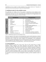
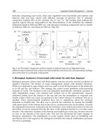
A pyrolysis gasification system developed in this study was composed of pyrolysis gasifier,
3-phase gliding arc plasma reformer, and fixed bed adsorber, as shown in figure 1.
Production of Activated Char and Producer Gas Sewage Sludge
137
A pyrolysis gasifier was designed to be a combined rig with a screw carbonizer for pyrolysis
of dried sludge and a rotary activator for steam activation of carbonized material. The screw
carbonizer was manufactured as feed screw type for carbonization of dried sludge. Feed
screw controls the holding time of dried sludge at carbonizer according to motor revolution
number. The screw carbonizer features dual pipe, and steam holes were installed at radial
direction of external wall, and high pressure steam is discharged to activator radially. The
rotary activator is composed of rotary drum with vane and pick-up flight, indirect heating
jacket, pyrolysis gas outlet, gas sampling port, char outlet, etc. Retention time of activated
sludge is controlled via number of rotation for a rotary drum. A sludge feeding device is for
holding of dried sludge in a dried sludge hopper which is installed at inlet of the combined
pyrolysis gasifier. A screw feeder is installed at the bottom of the hopper, and controls the
input amount of dried sludge via revolution number. The feeder feeds the dried sludge into
the screw carbonizer. A hot gas generator is for producing hot gas to heat a heating jacket
and supplys hot steam into a rotary drum. It was composed of a combustor with burner and
a steam generator.
A 3-phase gliding arc plasma reformer was installed at downstream of outlet for the
pyrolysis gasifier. The gliding arc plasma reformer utilized a quartz tube (55 mm in
diameter, 200 mm in height) for insulation and monitoring purposes, and a ceramic
connector (Al2O3, wt 96%) in electrode fixing was adopted for complete insulation between
three electrodes. The three conical electrodes in 120° (95 mm in length) were installed,
maintaining 3 mm gap. At the inlet of the plasma reformer, a orifice disc with 3 mm hole for
injection of producer gas was installed. A 3-phase AC high voltage power supply unit
(Unicon Tech., UAP-15K1A, Korea) was used for stable plasma discharge at the inside of the
plasma reformer.
A sludge char adsorber was made of a fixed bed cylinder (76 mm in diameter, 160 mm in
length), and installed at the rear section of the plasma reformer. To fix the packing material
at an adsorber, a porous distributer in stainless steel (25-mesh) was installed at the upper
part. The porous distributer was made in a honeycomb ceramic for preventing channeling
effect of input producer gas.
Fig. 1. Experimental setup of a pyrolysis gasification
138
Integrated Waste Management – Volume I
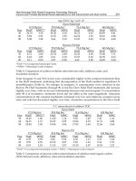
Experiment was conducted at optimal condition for high quality porosity in sludge char and
for the largest amount of combustible gas formation. The experimental conditions and each
temperature condition were given in table 1. All the data in experiments were taken after
stabilizing temperatures at each part, particularly the screw carbonizer and rotary activator.
After finishing experiment by setting condition, sludge char in a char outlet is cooled up to
room temperature by nitrogen passed the pyrolysis gasifier to protect the oxidation of the
sludge char by air. Gas was sampled for 5 minutes in a stainless cylinder at the sampling
ports of each pyrolysis gasifier, plasma reformer, and adsorber (Refer a gas sampling line in
section 2.3.2). For tar sampling, it was conducted for 20 minutes by tar sampling method (as
shown section 2.2), and total amount of gas was measured with a gas-flow meter. For a test,
the gas and tar sampling were conducted 3 times during test time of 120 minutes stably, and
the taken data were averaged. Adsorption capacity of sludge char was calculated from
weight of adsorber before/after experiment divided by test time.
Test conditions
Steam feed amount
(mL/min)
10
Temperature (°C) in each part
Moisture content of dried
sludge (%)1)
9.8
④Steam
generator
1,010
450
820
450
1) Moisture content of dried sludge is average number
①Combustor
②Carbonizer
③Activator
Retention time (min)
Activator
Carbonizer
30
30
⑤Plasma
reformer
400
⑥Adsorber
35
Table 1. Detailed conditions in each section
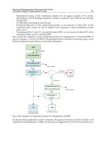
2.2 Tar sampling and analysis methods
Tar sampling and analysis were used by the method of biomass technology groups (BTGs)
(Good et al, 2005; Neeft, 2005; Phuohuakrat et al, 2010; Son et al, 2009; Yamazaki et al, 2005).
Wet sampling module was installed with 6 impingers (250 mL) in two separated isothermal
baths for adsorption of tar and particles. At the first isothermal bath, 100 mL of isopropanol
was filled into 4 impingers, respectively, along with 20°C of water. For the second bath,
isopropanol was filled while it was maintained at -20°C using mechanical cooling device
(ECS-30SS, Eyela Co., Japan). Among 2 impingers, 1 unit was filled with 100 mL of
isopropanol, and the other was left as empty. In the series of impinger bottles, the first
impinger bottle acts as a moisture and particle collector, in which water, tar and soot are
condensed from the process gas by absorption in isopropanol. Other impinger bottles collect
tars, and the empty bottle collects drop.
Immediately after completing the sampling, the content of the impinger bottles were filtered
through a filter paper (Model F-5B, Advantec Co., Japan). The filtered isopropanol solution
was divided into two parts; the first was used to determine the gravimetric tar mass by
means of solvent distillation and evaporation by evaporator (Model N-1000-SW, Eyela,
Japan) in which temperature and steam pressure were 55~57°C and 230 hPa, respectively.
The second was used to determine the concentrations of light tar compounds using GC-FID
(Model 14B, Shimadzu, Japan).
Quantitative tar analysis was performed on a GC system, using a RTX-5 (RESTEK) capillary
column (30 m - 0.53 mm id, 0.5 μm film thickness) and an isothermal temperature profile at
Production of Activated Char and Producer Gas Sewage Sludge
139
45°C for the first 2 min, followed by a 7 °C/min temperature gradient to 320°C and finally
an isothermal period at 320°C for 10 min. Helium was used as a carrier gas. The temperature
of the detector and injector were maintained at 340 and 250°C, respectively.
Fig. 2. Tar sampling line system
2.3 Sludge char and gas analysis
2.3.1 Pore development in sludge char
The structural characterization of the sewage sludge char was carried out by physical
adsorption of N2 at -196°C. The adsorption isotherms were determined using
nanoPOROSITY (Model nanoPOROSITY-XQ, MiraeSI Co. Ltd, Korea). The surface area was
calculated using the BET (Brauner-Emmet-Teller) equation. Using BJH (Barret-JoynerHalenda) equation, incremental pore volume and mean pore size was calculated. To
compare pore development in sludge char, SEM (scanning electron microscopy; Model S4800, Hitachi Co., Japan) was used, and image was taken at 50,000X resolution for
morphological analysis. Chemical properties and constituent components were analyzed via
EDX (Energy-dispersive X-ray spectroscopy; Model 7593-H, Horiba, UK).
2.3.2 Sampling and analysis producer gas
The produced gas was sampled for 5 minutes in a stainless cylinder as sampling gas flow
rate is 1 L/min. As can be seen in figure 2, a set of backup VOC adsorber was installed
downstream of the series of impinger bottles to protect the column of the gas
chromatography from the residual solvent or VOCs, which may have passed through the
impinger train. The set of backup VOC adsorber consists of two cotton filters and an
activated carbon filter connected in a series. Gas analysis was conducted with GC-TCD
(Model CP-4900 Varian, Netherland). MolSieve 5A PLOT column for H2, CO, O2, and N2
and PoraPLOT Q column for CO2, CH4, C2H4, and C2H6 were used for simultaneous
analysis.
3. Results and discussion
3.1 Dried sludge characteristics
Sludge from a local wastewater treatment plant was dewatered by a centrifuging. And then
the dewatered sludge was dried to less than 10% of moisture content using a rotary kiln
type dryer developed by the corresponding researcher. The pyrolysis gasification is a
140
Integrated Waste Management – Volume I
process of which heat is applied by external source or partial oxidation. Vaporization
temperature of moisture is lower than thermal decomposition temperature for organic
compound in sludge. Therefore, high moisture content in sewage sludge will show
significant energy loss due to preemptive utilization of the heat for drying.
In addition, delayed pyrolysis gasification will affect the producer via reaction with
moisture and reactant. Therefore, less than 10% of moisture content in the dried sludge was
taken for this study.
Table 2 shows proximate analysis and ultimate analysis on the dried sludge.
Proximate analysis (%)
Moisture
9.7
Ultimate analysis (%)
C
52.3
Volatile matter
51.7
H
8.2
Fixed carbon
6.1
O
32.2
Ash
32.5
N
7.92
S
0.01
Table 2. Properties of the dried sludge
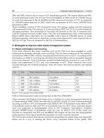
3.2 Thermal behavior analysis
To determine pyrolysis temperature, TGA (thermo gravimetric analysis) and DTG (derived
thermo-gravimetric) analysis was shown in figure 3. According to TGA and DTG results, the
maximum weight loss temperature and final decomposition temperature, etc can be derived
(Karayildirim et al, 2006).
100
80
Weight loss (%)
0.15
TGA
60
0.1
40
0
0.05
DTG
20
0
100
200
300
400
500
600
Temperature (oC)
700
800
Rate of weight loss (%/sec)
0.2
0
900
Fig. 3. TGA and DTG for pyrolysis of the dried sewage sludge
Thermal decomposition of the dried sludge showed weight loss after evaporation of small
moisture content at 100~150°C as shown in DTG curve. This could be elucidated by two
steps. First step (primary pyrolysis) is discharging of volatile component at 200~500°C, and
the second step is decomposition of inorganic compound at over 500°C. First step for
volatile component discharge displayed two peaks, and it can be explained as follows. The
first peak might be due to decomposition and devolatilization of less complex organic
141
Production of Activated Char and Producer Gas Sewage Sludge
structures which is a small fraction. The second peak was caused by decomposition of more
complex organic structures corresponding to a larger fraction. Second step (secondary
pyrolysis) is related to decomposition of inorganic compound as described before. In first
step, TGA displayed 57% at 500°C, and 900°C for the second step was 46.2%. That is, 43% of
moisture content and volatile component was discharged during the first step, and in
second step 10.8% reduction (from first step) was corresponded to decomposing ash which
is an inorganic component in dried sludge.Therefore, for the pyrolysis gasification
experiment in purpose of improved yield of producer gas and higher adsorption rate,
pyrolysis carbonization were maintained at 450°C which discharges the largest amount of
volatile component, and steam activation was set to 850°C for increasing the porosity in the
sludge char.
3.3 Characteristics of a pyrolysis gasifier
Figure 4 shows mass yield for char, tar, and gas from a pyrolysis gasifier. The product
amount ordered was producer gas of 43.6%, sludge char of 35.4% and tar of 21%. As
described before, the corresponding experiment setup was made to primary pyrolysis
carbonization at screw carbonizer which is set to 450°C and post-activation at rotary kiln
activator along with steam injection, which is set to 820°C.
Producer gas was formed by decomposition and volatilization of organic compound in a
screw carbonizer (refer first step description of DTG in figure 3), and gas formation was
increased due to steam reforming of tar and char in a rotary kiln activator. Sludge char in
mass was reduced by vaporization of volatile component during the passing of the
carbonizer, and steam gasification and inorganic decomposition in the activator. Heavy tar
was formed and then it was converted into producer gas and light tar at the activator.
50
43.6
40
Mass yield (%)
35.4
30
21.0
20
10
0
Char
Tar
Gas
Fig. 4. Mass yield of the products
3.3.1 Characteristics of the sludge char
Figure 5 compares incremental pore volume and SEM photos of the dried sludge and sludge
char. The pore size classification in this study follows the IUPAC classification (IUPAC,
1982; Lu, 1995) i.e. micropores (<20 Å), mesopores (20∼500 Å) and macropores (>500 Å). Pore
142
Integrated Waste Management – Volume I
of sludge char after carbonization activation showed significant increase compared to the
dried sludge, and pore distribution was less than 500 Å, which is comprised of micropores
and mesopores. The pyrolysis gasifier in this study had been designed as continuously
combined type for carbonization of dried sludge at a screw carbonizer and steam activation
at a rotary activator. The dried sludge experienced evaporating of moisture and
decomposing of organic component for pore development through passing the screw
carbonizer (Lu, 1995). And then carbonized material was exposed to steam at the rotary
activator for the formation and development of micropoees and mesopores. For steam
activation in developing micropores, steam should deeply penetrate into pores of the
carbonized material for surface reaction. High temperature activation had the benefit of
diffusion and penetration of the steam to develop micropore. On the other hand, it was
blocked by tar in the carbonized material, resulted as well-developed mesopore. This is the
reason that the sludge char from the carbonization activation had well-developed
micrepores and mesopores. Sludge drying was made with a parallel flow rotary kiln drier
with direct-hot gas application. Hot gas inflow in turbulent flow was directly contacted with
the dewatered sludge in the dryer. Inside of the dryer was set to 255°C in average value.
For dried sludge, small portion of micropore and mesopore was formed. It is considered to
be formed due to discharging of volatile organic material and dehydroxlation of inorganic
material from the dried sludge. Bagreev et al. proved that water released by the
dehydroxylation of inorganic material could aid pore formation and moreover could act as
an agent for creating micropores (Bagreev et al, 2001). In addition, Inguanzo et al. proposed
that carbonization increases the porosity through unblocking many of the pores obscured by
volatile matter (Inguanzo et al, 2001). Surface of the dried sludge from SEM photograph in
50,000 times of magnification shows smooth surface with less pores, but the sludge char
presents overall formation of pores.
0.003
Sludge char
3
Incremental pore volume (cm /g A)
Dried sludge
0.0025
0.002
0.0015
20 A
20 A
0.001
0.0005
0
20
100
500
1000
Average pore diameter (A)
Fig. 5. Incremental pore volume and SEM images of the dried sludge and sludge char
Table 3 compares the results of the sludge char made from this study and 3 types adsorbent
from the study of Thana Phuphuakrat etc (Phuphuakrat et al, 2010). For the sludge char,
143
Production of Activated Char and Producer Gas Sewage Sludge
specific surface area and pore volume were smaller than commercial activated carbon, and
mean pore size was larger. The sludge char displayed mesopore similar to wood chip and
synthetic porous cordierite, but the activated carbon featured micropore.
Adsorption capability of the sludge char was less than the one with wood chip, but larger
than the one of activated carbon and synthetic porous cordierite. The adsorption experiment
in this study was conducted by using benzene only. So the comparison in the adsorption
capacity has difficulty because the study of Thana Phuphuakrat etc was achieved in a
continuous test rig using Japanese cedar which produced pyrolysis gas including all tars
and water. However, it might be considered that the wood chip adsorbed large amount of
steam when compared to the sludge char, because of hydrophilic surface and mesoporous
material favoring water adsorption. Although the test in non-condensable light aromatic
hydrocarbon (e.g. benzene) was conducted in this study, it should be expected for the
sludge char to adsorb well for the condensable light PAH (e.g. naphthalene, anthracene,
pyrene) due to having mesopores as proved in the other study.
Adsorbent
Specific surface
area (m2/g)
Sludge char1)
98.1
Activated
987.1
carbon
Wood chip
1.072
Synthetic
porous
6.045
cordierite
1) Sludge char from this study
Mean pore size
(Å)
Pore volume
(cm3/g)
63.49
0.2354
Adsorption
capacity
(mg/g)
120.6
11.28
0.5569
97.5
100.77
0.0058
155.7
27.43
0.0083
12.8
Table 3. Porous characteristics and adsorption capacity of the adsorbents from this study
and other results (Phuohuakrat et al, 2010)
A semi quantitative chemical analysis of dried sludge and sludge char, figure 6 and table 4,
was obtained from the EDX analyzer coupled to SEM measurements. The results indicate
that both samples present relatively high carbon content in addition to mineral components.
The relative amount of carbon decreased after carbonization and activation, as expected
considering the decomposition of the organic components.
These atoms might be considered as the potential catalysts for pyrolysis reaction. For
example, with Al, if existing in the form of Al2O3, it would be an acid catalyst for cracking
reaction (Sinfelt & Rohrer, 1962); or with K, and Ca atoms, they were already reported as the
catalyst for biomass pyrolysis in literature (Yaman, 2004).
Figure 7 shows the N2 adsorption-desorption isotherm for the dried sludge and sludge char.
According to the isothermal adsorption graphs, the dried sludge exhibited only a small
amount of adsorption, but the sludge char displayed a larger amount of adsorption at lower
nitrogen concentrations. As shown in figure 5, the sludge char exhibited well-developed
micro- and meso-pore structures. The analysis on the adsorption isotherm provides an
assessment for the pore size distribution. According to the IUPAC classification, the curve of
the sludge char corresponds to Type V isotherm. A characteristic of the Type V isotherm is
the hysteresis loop, which is associated with the capillary condensation in mesopores and
limiting uptake at high relative pressure (Khalili et al, 2000).
144
Integrated Waste Management – Volume I
1000
C
Dried sludge
Sludge char
Counts
800
600
O
Si
Al
400
200
0
P
Mg
S
0
Cl
K Ca
2
4
Ti
Fe
Ba
Energy (keV)
Zn
6
8
10
Fig. 6. EDX spectrums of dried sludge and sludge char
Item
C
O
Mg Al
Si
P
S
Cl
K
Ca
Ti
Fe Zn Ba
Dried
sludge 53.65 44.62 0.06 0.23 0.45 0.55 0.03 0.01 0.06 0.07 0.01 0.24 0.02 0
(wt %)
Sludge
char 47.65 44.83 0.14 1.21 5.34 0.46 0.03 0.02 0.09 0.11 0 0.21 0 0.01
(wt %)
Table 4. Elements content of dried sludge and sludge char
180
Adsorbed amount of N2 (cm3/g)
160
Dried sludge adsorption
Dried sludge desorption
Sludge char adsorption
Sludge char desorption
140
120
100
80
60
40
20
0
0
0.2
0.4
0.6
Relative pressure (P/Po)
Fig. 7. Isothermal adsorption-desorption linear plot
0.8
1
145
Production of Activated Char and Producer Gas Sewage Sludge
3.3.2 Tar characteristics for the pyrolysis gasification
Results produced from the pyrolysis gasifier were shown in table 5.
Representative tars for the corresponding benzene ring were selected to benzene (1 ring),
naphthalene (2 ring), anthracene (3 ring) and pyrene (4 ring). And the representative tars
with nitrogen for the sewage sludge (Fullana et al, 2003) were taken as benzonitrile and
benzeneacetonitrile. Gravimetric tar was 26.3 g/Nm3. Total concentration of light tar was
10.9 g/Nm3, and its amount order was benzene, naphthalene, benzonitrile,
benzeneacetonitrile, anthracene, and pyrene. Dried sludge formed sludge char, tar, and gas
during pyrolysis at screw carbonizer, and then steam activation was achieved in rotary
activator. The gravimetric tar is total amount of tar after passing carbonization and
activation process. Benzene and naphthalene among light tar are products produced during
secondary pyrolysis at carbonizer, and some part of both tars converts to gas during steam
activation at activator. In addition, anthracene and pyrene were directly formed by primary
pyrolysis from dried sludge at carbonizer. Both tars should be known as not affecting by
carbonization-activation temperature and steam amount (Umeki, 2009).
Gravimetric
tar
26.3
Benzene
Naphthalene
Anthracene
Pyrene
6.31
2.97
0.87
0.12
Benzonitrile
0.61
Benzeneacetonitrile
0.11
Table 5. Tar concentrations from a pyrolysis gasifier (unit: g/Nm3)
3.3.3 Producer gas characteristics
Table 6 shows producer gas concentration and higher heating value from a pyrolysis
gasifier. Major components in gas were analyzed to be hydrogen, carbon monoxide,
methane, and carbon dioxide along with trace amount of nitrogen and oxygen. The higher
heating value was 13,400 kJ/Nm3 having half value of natural gas.
H2
CO
CH4
CO2
C2H4
C2H6
O2
N2
41.2
17.3
9.5
15.4
0
0
0.5
3.3
Higher
heating value
13,400
Table 6. Concentration of producer gas (dry vol. %) and higher heating value (kJ/Nm3)
Hydrogen was produced by the cracking of the volatile matter generated by the pyrolysis
gasification. Methane resulted from cracking and depolymerization reactions, while carbon
monoxide and carbon dioxide were produced from decarboxylation and depolymerization
or the secondary oxidation of carbon (Xiao et al, 2010). In addition, the presence of steam at
high temperatures gave rise to in situ steam reforming of the volatile matters and partial
gasification of the solid carbonaceous residue, as shown in the reactions of Eqs. (1) and (2).
Non-condensable products may also undergo gas phase reactions with each other. For
example, the CO and CH4 contents may be affected by the methane gasification and water
gas shift reactions, as shown in Eqs. (3) and (4) (Domínguez et al, 2006).
Steam reforming reaction:
Organics ( g ) H 2O ( g ) CO H 2
-
(1)
Steam gasification reaction:
C ( s ) H 2O ( g ) CO H 2 , H 298 K 132kJ mol 1
(2)
146
-
Integrated Waste Management – Volume I
CH4 gasification reaction:
CH 4 H 2O CO 3H 2 , H 298 K 206.1kJ mol 1
CO H 2O CO2 H 2 ,
-
(3)
(4)
CO shift reaction:
H 298 K 41.5 kJ mol 1
High temperatures were also responsible for the reduction of C2H4, C2H6 and C3H8. Some of
the typical reactions are as follows (Zhang et al, 2010):
C2 H 6 C2 H 4 H 2
(5)
C2 H 4 CH 4 C
(6)
However, it should be noted that the gas composition may not exclusively be the result of
tar cracking and the partial gasification of char due to the complicated interactions of the
intermediate products, which would probably affect the final gas composition.
3.4 Plasma reformer and adsorber characteristics
The plasma reformer was installed for converting produced tar from the pyrolysis gasifier
into syngas via decomposition and steam reforming. In addition, the fixed bed adsorber was
implemented for adsorption of by-passed tar from the plasma reformer.
3.4.1 Tar destruction performance
Fig. 8 shows the results of tar sampling at the rear section of the pyrolysis gasifier, plasma
reformer, and fixed bed adsorber. Gravimetric tar concentration at the outlet of
carbonization activator was 26.3 g/Nm3, and it was reduced to 4.4 g/Nm3 at the reformer
outlet. Decomposition efficiency of the corresponding gravimetric tar was 83.2%. For light
tar, total amount of carbonization activator outlet was 10.9 g/Nm3. The concentration was
reduced to 1.3 g/Nm3 at the outlet of reformer, and the destruction efficiency of the light tar
was 87.9%. Each concentration of the light tars was found to be 0.62 g/Nm3 for benzene,
0.45 g/Nm3 for naphthalene, 0.14 g/Nm3 for anthracene, 0.021 g/Nm3 for pyrene, 0.08
g/Nm3 for benzonitrile, and 0.015 g/Nm3 for benzeneacetonitrile.
Decomposition of heavy tar was happened due to plasma cracking and carbon formation in
Eqs. (7) and (8) (Tippayawong & Inthasan, 2010). In addition, steam in producer gas from
the pyrolysis gasifier formed excitation species as shown in Eq. (9), and the radicals reduced
light tar and carbon black which produce by the reactions of plasma cracking and carbon
formation (Guo et al, 2008). It is remarkable that the tars from the pyrolysis gasification
should be decomposed significantly by the plasma reformer.
Plasma cracking:
pCn H x qCm H y rH 2
-
(7)
Cn H x nC ( x / 2) H 2
(8)
Carbon formation:
147
Production of Activated Char and Producer Gas Sewage Sludge
-
Water excitation:
H 2O H , e eq , OH , H 2 , H 2O2 , H 3O , Oh
(9)
In Eq. (9), CnHx represents tar, such as the large molecular compounds, and CmHy represents
a hydrocarbon with a smaller carbon number compared to that of CnHx.. Discharged
residual tar from the plasma reformer was removed by the fixed bed adsorber filled with
sludge char. Gravimetric tar at the adsorber outlet displayed 0.5 g/Nm3, which is 88.6% of
removal efficiency. Total amount of light tar was 0.39 g/Nm3, which is corresponded to
40.5% of removal efficiency. The relevant concentration was 0.28 g/Nm3 for benzene, 0.09
g/Nm3 for naphthalene, 0.14 g/Nm3 for anthracene, 0.01 g/Nm3 for benzonitrile, and 0.003
g/Nm3 for benzeneacetonitrile. Among residual tar, heavy tar was mostly removed at
adsorber, and non-condensed light tar that was not adsorbed was considered to be passed
through the adsorber. For satisfactory IC engine operation, an acceptable particle content
<50 mg/Nm3 and a tar content <100 mg/Nm3 is postulated (Milne et al, 1998). Therefore, 0.5
g/Nm3 of tar concentration in producer gas is sufficient for utilization. In addition,
sampling analysis on particulate matter was not conducted in this study, but the carbon
black was not formed due to steam reforming at the plasma reformer. Therefore, it is not
considered to be problematic in the operation.
30
8
26.3
7
20
5
15
4
2.97
3
10
4.4
5
2
0.62
0.28
0.5
0
Gravimetic
tar
Light tar (g/Nm3)
6
3
Gravimetric tar (g/Nm )
Pyrolysis gasifier
Plasma reformer
Adsorber
6.31
25
Benzene
0.45
0.09
Naphthalene
0.87
0.14
0
Anthracene
0.12
0.02
0
Pyrene
0.11
0.61
0.08
0.01
Benzonitrile
0.01
0
Benzeneacetonitrile
1
0
Fig. 8. Gravimetric tar and light tar concentrations
3.4.2 Gas formation characteristics
Figure 9 shows the producer gas analysis sampled from the pyrolysis gasifier, plasma
reformer, and fixed bed adsorber, respectively. At the outlet of plasma reformer, gas
concentration was found to be 50.9% for H2, 22.3% for CO, 11% for CH4, 8.7% for CO2, 0.4%
for C2H2, and 0.2% for C2H4. Concentration of hydrogen, carbon monoxide, and light
hydrocarbon (methane, ethylene, and ethane) were increased compared to the outlet
concentration of pyrolysis gasifier. For hydrogen and carbon monoxide, it was increased
148
Integrated Waste Management – Volume I
due to Eqs. (1) and (3), steam reforming and methane gasification reaction, respectively.
Light hydrocarbon was converted from light tar using tar plasma cracking reaction (7) in
portion and from chain reactions of Eqs. (5) and (6). In addition, decrease in carbon dioxide
was considered to be dry reforming as shown in Eq. (10) (Devi et al, 2005).
Cn H x nCO2 ( x / 2) H 2 2nCO
(10)
According to gas analysis results at adsorber outlet, 50.5% of H2, 21.9% of CO, 10.5% of CH4,
7.7% of CO2, and 0.1% of C2H2 were displayed. Compared to the results at plasma reformer
outlet, the corresponding concentration was slightly decreased within measurement
tolerance, but it was not almost adsorbed. Higher heating value calculated using the gases
from each outlet. It was found to be 11,200 kJ/Nm3 for producer gas from the pyrolysis
gasifier, 13,992 kJ/Nm3 for the plasma reformer and 13,482 kJ/Nm3 for the adsorber. The
increase at the plasma reformer outlet is due to increased amount of combustible gases,
particularly methane having high calorific value.
60
50.9
Pyrolsis gasifier
Plasma reformer
Adsorber
50.5
Gas concentration (%)
50
41.2
40
30
22.3
17.3
21.9
20
11
9.5
10.5
15.4
8.7
7.9
10
0
0.4
0.1
0
H2
CO
CH 4
CO2
C 2H 2
0
0.2
0
C2H 4
0.5
0.8
0.9
O2
3.3
1.8
2.5
N2
Fig. 9. Producer gas concentrations at exit of each part
4. Conclusions
To utilize dried sewage sludge as energy and resource, pyrolysis gasifier, plasma reformer,
and fixed bed adsorber system were established. From the pyrolysis gasifier, sludge char
and pyrolysis gases were produced along with small amount of tar. To improve tar
adsorption capability of sludge char, an integrated pyrolysis gasifier was developed for
achieving in sequential carbonization and activation. In addition, for higher producer gas
yield and tar reduction, a plasma reformer was installed at the rear section of the pyrolysis
gasifier, and a fixed bed adsorber, which contains sludge char from the pyrolysis gasifier,
Production of Activated Char and Producer Gas Sewage Sludge
149
was implemented for adsorption of residual tars. Sludge char from the pyrolysis gasifier
displayed 98.1 m2/g of specific surface area and 63.49 Å of mean pore size, showing the
distribution of mesopore and micropore with superior adsorption capability. Producer gas
was mostly comprised of hydrogen, carbon monoxide, methane, and carbon dioxide, and
the corresponding higher heating value was 13,400 kJ/Nm3. Gravimetric tar was 26.3
g/Nm3, and total amount of light tar was 10.9 g/Nm3, which showed benzene, naphthalene,
benzonitrile, and benzeneacetonitrile according to the concentration level. Plasma reformer
featured tar cracking and steam reformation, and decomposition efficiency of gravimetric
tar was 83.2%, which is corresponded to 4.4 g/Nm3. For light tar, total amount was 1.3
g/Nm3, which is 87.9% of decomposition efficiency. Hydrogen, carbon monoxide, and
methane among the components of reforming gas were increased, having 13,992 kJ/Nm3 of
higher heating value. Gravimetric tar at the adsorber outlet was 0.5 g/Nm3, which is 88.6%
of decomposition efficiency. Total amount of light tar was 0.39 g/Nm3, and it was 40.5% of
decomposition efficiency. According to gas analysis results, 50.5% of H2, 21.9% of CO, 10.5%
of CH4, 7.7% of CO2, and 0.1% of C2H2 were displayed, and the corresponding higher
heating value was 13,482 kJ/Nm3. Therefore, carbonization-activation of sludge can form
sludge char that could be utilized for tar adsorption, and the relevant clean producer gas is
proved to be applicable for heat engine.
5. References
Bagreev, A., Bandosz, T. J. & Locke, D. C. (2001). Pore structure and surface chemistry of
adsorbents obtained by pyrolysis of sewage sludge-derived fertilizer, Carbon,
Vol.39, No.13, pp. 1971-1979, ISSN 0008-6223.
Bergman, P. C. A. van Paasen, S. V. B. & Boerrigter, H. (2002). The novel “OLGA”
technology for complete tar removal from biomass producer gas, Pyrolysis and
Gasification of Biomass and Waste, Expert Meeting, ISBN 1872691773, Strasbourg,
France, 30 September - 1 October 2002.
Devi, L., Ptasinski, K. J. & Janssen, F. J. J. G. (2003). A review of the primary measures for tar
elimination in biomass gasification processes, Biomass and Bioenergy Vol.24, No.2,
pp. 125-140, ISSN 0961-9534.
Devi, L., Ptasinski, K. J., Janssen, F. J. J. G., van Paasen, S. V. B., Bergman, P. C. A. & Kiel, J.
H. A. (2005). Catalytic decomposition of biomass tars: use of dolomite and
untreated olivine, Renewable Energy, Vol.30, No.4, pp. 565-587, ISSN 0960-1481.
Dogru, M., Midilli, A. & Howarth, C. R. (2002). Gasification of sewage sludge using a
throated downdraft gasifier and uncertainty analysis, Fuel Processing Technology,
Vol. 75, No.1, pp. 55-82, ISSN 0378-3820.
Domínguez, A., Menéndez, J. A. & Pis, J. J. (2006). Hydrogen rich fuel gas production from
the pyrolysis of wet sewage sludge at high temperature, Journal of Analytical and
Applied Pyrolysis, Vol.77, No.2, pp. 127-132, ISSN 0165-2370.
Du, C. M., Yan, J. H. & Cheron, B. (2007). Decomposition of toluene in a gliding arc
discharge plasma reactor, Plasma Sources Science and Technology, Vol.16, pp. 791-797,
ISSN 0963-0252.
Fullana, A., Conesa, J. A., Font, R. & Martín-Gullón, I. (2003). Pyrolysis of sewage sludge:
nitrogenated compounds and pretreatment effects, Journal of Analytical and Applied
Pyrolysis, Vol.68-69, pp. 561-575, ISSN 0165-2370.
150
Integrated Waste Management – Volume I
Good, J., Ventress, L., Knoef, H., Zielke, U., Hansen, P. L. van de Kamp, W., de Wild, P.,
Coda, B., van Paasen, S., Kiel, J., Sjöström, K., Liliedahl, T., Unger, Ch., Neeft, J.,
Suomalainen, M. & Simell, P. (2005). Sampling and analysis of tar and particles in
biomass producer gases, Technical Report, BTG biomass technology group CEN BT/TF
143, pp. 1-44.
Guo, Y., Liao, X. & Ye, D. (2008). Detection of hydroxyl radical in plasma reaction on toluene
removal, Journal of Environmental Sciences, Vol.20, No.12, pp. 1429-143, ISSN 10010742.
Hosokai, S., Hayashi, J. I., Shimada, T., Kobayashi, Y., Kuramoto, K., LI, C. Z. & Chiba, T.
(2005). Spontaneous generation of tar decomposition promoter in a biomass steam
reformer, Chemical Engineering Research & Design, Vol.83, No.A9, pp. 1093-1102,
ISSN 0263-8762.
Inguanzo, M., Mendez, J. A., Fuente, E. & Pis, J. J. (2001). Reactivity of pyrolyzed sewage
sludge in air and CO2, Journal of Analytical and Applied Pyrolysis, Vol.58-59, pp. 943954, ISSN 0165-2370.
Inguanzo, M., DomInguez, A., Menéndez, J. A., Blanco, C. G. & Pis, J. J. (2002). On the
pyrolysis of sewage sludge: the influence of pyrolysis conditions on solid, liquid
and gas fractions, Journal of Analytical and Applied Pyrolysis, Vol.63, No.1, pp. 209222, ISSN 0165-2370.
IUPAC. (1982). Manual of Symbols and Terminology of Colloid Surface, Butterworths,
London.
Karayildirim, T., Yanik, J., Yuksel, M. & Bockhom, H. (2006). Characterization of products
from pyrolysis of waste sludges, Fuel, Vol.85, No.10-11, pp. 1498-1508, ISSN 00162361.
Khalili, N. R., Campbell, M., Sandi, G. & Golaś, J. (2000). Production of micro- and
mesoporous activated carbon from paper mill sludge: I. Effect of zinc chloride
activation, Carbon, Vol.38, No.14, pp. 1905-1915, ISSN 0008-6223.
Lu, G. Q. (1995). Effect of Pre-Drying on the Pore Structure Development of Sewage Sludge
during Pyrolysis, Environmental Technology, Vol.16, No.5, pp. 495-499, ISSN 09593330.
Milne, T. A., Evans, R. J. & Abatzoglou, N. (1998). Biomass gasifier "Tars'': their nature,
formation and conversion, National Renewable Energy Laboratory (NREL), report
NREL/TP-570-25357.
Nair, S. A., Pemen, A. J. M., Yan, K., van Gompel, F. M., van Leuken, H. E. M., van Heesch,
E. J. M., Ptasinski, K. J. & Drinkenburg, A. A. H. (2003). Tar removal from biomassderived fuel gas by pulsed corona discharges, Fuel Processing Technology, Vol. 84,
No.1-3, pp. 161-173, ISSN 0378-3820.
Nair, S. A., Yan, K., Pemen, A. J. M., van Heesch, E. J. M., Ptasinski, K. J. & Drinkenburg, A.
A. H. (2005). Tar Removal from Biomass Derived Fuel Gas by Pulsed Corona
Discharges: Chemical Kinetic Study II, Industrial & Engineering Chemistry Research,
Vol.44, No.6, pp. 1734-1741, ISSN 0888-5885.
Neeft, J. P. A. (2005). Rationale for setup of impinger train, SenterNovem CEN BT/TF 143, pp.
1-14.
Production of Activated Char and Producer Gas Sewage Sludge
151
Onozaki, M., Watanabe, K., Hashimoto, T., Saegusa, H. & Katayama, Y. (2006). Hydrogen
production by the partial oxidation and steam reforming of tar from hot coke oven
gas, Fuel, Vol.85, No.2, pp. 143-149, ISSN 0016-2361.
Pfeifer, C. & Hofbauer, H. (2008). Development of catalytic tar decomposition downstream
from a dual fluidized bed biomass steam gasifier, Powder Technology, Vol. 180, No.12, pp. 9-16, ISSN 0032-5910.
Phuphuakrat, T., Namioka, T. & Yoshikawa, K. (2010). Tar removal from biomass pyrolysis
gas in two-step function of decomposition and adsorption, Applied Energy, Vol. 87,
No.7, pp. 2203-2211, ISSN 0306-2619.
Phuphuakrat, T., Nipattummakul, N., Namioka, T., Kerdsuwan, S. & Yoshikawa, K. (2010).
Characterization of tar content in the syngas produced in a downdraft type fixed
bed gasification system from dried sewage sludge, Fuel, Vol.89, No.9, pp. 22782284, ISSN 0016-2361.
Sinfelt, J. H. & Rohrer, J. C. (1962). Cracking of Hydrocarbons over a promoted Alumina
Catalyst. The Journal of Physical Chemistry, Vol.66, No.8, pp. 1559-1560, ISSN 00223654.
Son, Y. I., Sato, M., Namioka, T. & Yosikawa, K. (2009). A Study on Measurement of Light
Tar Content in the Fuel Gas Produced in Small-Scale Gasification and Power
Generation Systems for Solid Wastes, Journal of Environment and Engineering, Vol.4,
No.1, pp. 12-23, ISSN 1880-988X
Tippayawong, N. & Inthasan, P. (2010). Investigation of Light Tar Cracking in a Gliding Arc
Plasma System, International Journal of Chemical Reactor Engineering, Vol.8, pp. 1-16,
ISSN 1542-6580.
Umeki, K. (2009). Modeling and simulation of biomass gasification with high temperature
steam in an updraft fixed-bed gasifier, Doctoral thesis, pp. 1-148.
Xiao, R., Chen, X., Wang, F. & Yu, G. (2010). Pyrolysis pretreatment of biomass for
entrained-flow gasification, Applied Energy, Vol.87, No.1, pp. 149-155, ISSN 03062619.
Yaman, S. (2004). Pyrolysis of biomass to produce fuels and chemical feedstocks, Energy
Conversion and Management, Vol.45, No.5, pp. 651-671, ISSN 0196-8904.
Yamazaki, T., Kozu, H., Yamagata, S., Murao, N., Ohta, S., Shiva, S. & Ohba, T. (2005). Effect
of Superficial Velocity on Tar from Downdraft Gasification of Biomass, Energy &
Fuels, Vol.19, No.3, pp. 1186-1191, ISSN 0887-0624.
Yu, L., Li, X. D., Tu, X., Wang, Y., Shengyong, L. & Jianhua, Y. (2010). Decomposition of
Naphthalene by dc Gliding Arc Gas Discharge, Journal of Physical Chemistry A,
Vol.114, No.1, pp. 360-368, ISSN 1089-5639.
Yu, L., Tu, X., Li, X., Wang, Y., Yong, C. & Jianhua, Y. (2010). Destruction of acenaphthene,
fluorene, anthracene and pyrene by a dc gliding arc plasma reactor, Journal of
Hazardous Materials, Vol.180, No.1-3, pp. 449-455, ISSN 0304-3894.
Zhang, K., Li, H. T., Wu, Z. S. & Mi, T. (2009). The thermal cracking experiment research of
tar model compound, International Conference on Energy and Environment Technology,
ISBN 978-0-7695-3819-8, Guilin, China 16-18 October 2009.
152
Integrated Waste Management – Volume I
Zhang, B., Xiong, S., Xiao, B., Dongke, Y. & Jia, X. (2010). Mechanism of wet sewage sludge
pyrolysis in a tubular furnace, International Journal of Hydrogen Energy In Press,
Corrected Proof, pp. 1-9, ISSN 0360-3199.
9
Modelled on Nature – Biological Processes
in Waste Management
Katharina Böhm, Johannes Tintner and Ena Smidt
BOKU - University of Natural Resources and Life Sciences, Vienna
Austria
1. Introduction
Biological degradation and transformation of organic substances under aerobic or anaerobic
conditions are key processes within the natural metabolism of an equilibrated circulation
system in order to handle the accumulating biomass. These fundamental processes are the
basis for management strategies focusing on the biological treatment of organic waste
materials. They are subjected to the biochemical metabolism using the capability of
microbial populations to degrade, transform and stabilise organic matter. Stabilisation
comprises biological as well as abiotic chemical and physical processes and their interaction.
Avoiding greenhouse gases and shortening the after care period stabilisation is the key
target for safe waste disposal in landfills. Biogenic waste materials are a source of secondary
products: biogas obtained by anaerobic digestion and composts produced under aerobic
conditions. For composts stabilisation is a relevant process to achieve plant compatibility
and persistent organic substances for soil amelioration. Biological processes additionally
contribute to landfill remediation, e.g. by methane oxidation.
Nevertheless, biological degradation of waste materials is ambivalent and can lead to
harmful effects if microbial activities take place under uncontrolled conditions in
imbalanced systems. Abandoned landfills from the past demonstrate this fact.
Anthropogenic organic wastes differ from “natural” organic waste by their amount, their
heterogeneity and the content of xenobiotics. Therefore it is necessary to support and
optimise biological degradation of waste organic matter by adequate process operation and
technical devices. The equilibrium of necessary mineralisation and accessible humification is
a topic of high interest in the context of carbon fixation.
“Optimisation” is no aspect in the context with natural degradation processes. Additionally
they are not harmless a priori. They take place under the current conditions, but it can be
assumed that an equilibrium is reached over longer periods of time. Changes of
environmental conditions by anthropogenic activities can accelerate biological degradation.
Peat bogs that were drained and amended with carbonates lose organic matter due to
mineralisation (Küster, 1990). The pH value, water and air supply and temperature mainly
influence the transformation rate. This fact indicates that biodegradability is not only an
inherent property that depends on chemical and physical features of the material. The
behaviour of biodegradable substances is affected by the interaction of both material
characteristics and environmental conditions.
154
Integrated Waste Management – Volume I
This chapter provides an overview of biological processes in waste management, targets and
benefits, weak points and optimisation potential, process and product control by modern
analytical tools such as FT-IR spectroscopy and thermal analysis.
2. Composting and anaerobic digestion - Environmental benefits of resource
recovery
The biological treatment of waste materials primarily focuses on stabilisation of organic
matter in order to avoid gaseous emissions after waste disposal. The aspect of resource
recovery has gained in importance during the last two decades. Although resource recovery
has been practiced in the past, e.g. by composting of organic residues, this idea is currently
going through a renaissance, primarily due to the necessity of energy supply and increase of
soil organic matter by compost application. The retrieval of chemical products from waste
materials is also under discussion.
The knowledge about the biodegradability and microbial processes is a prerequisite for the
optimum use of biogenic waste. The heterogeneous composition of the incoming material
additionally demands a certain flexibility and adaptation according to basic requirements.
In many cases there is a potential for process optimisation.
Soil improvement by compost application and its relevance to carbon storage and climate
change
The benefits of compost application have been known for long time. According to
historical traditions clever farmers recognised the value of “rotted” and “putrefying”
organic waste for soil amelioration (Bruchhausen 1790, cited by Eckelmann, 1980).
Compost management for many centuries has led to the formation of anthropogenic soils
in several north-western European countries and in Russia (Hubbe et al., 2007). These so
called “Plaggensoils” represent an impressive example of organic matter increase by
compost application. “Terra preta” in the Amazon region also attests to the long-term
effect of organic matter brought into soil by anthropogenic activities and organic waste
(Sohi et al., 2009). Long-term experiments that have been initiated in the 19th century
provide useful data on the effects of organic matter amendments and their long-term
behaviour (Jenkinson & Rayner, 1977).
Agricultural activities, tillage and the application of mineral fertilisers have promoted losses
of organic matter in soils that have caused their degradation to a certain degree.
“Desertification” has become a keyword in this context (Montanarella, 2003). The current
issue of climate change has additionally attracted notice to carbon losses. The maintenance
of organic matter and organic carbon is an effective measure to reduce CO2 emissions.
Besides technical approaches of carbon sequestration, prevention of carbon losses in soils by
adequate tillage and compost application, which seems an effective measure should be
given priority. Composts with high humic substance contents play a crucial role as they
favour the fixation of carbon and minimise the losses.
How compost organic matter is integrated in different soil carbon pools is a topic of high
interest in order to evaluate the stability and the long-term behaviour. Different approaches
have been applied to identify and describe the carbon pools in soils (Six et al., 2000a; Six et
al., 2000b; Pulleman & Marinissen, 2004). These methods can be applied to amended soils in
order to trace the fate of compost organic matter and to quantify the contribution of
composts to the stable carbon pool.
Modelled on Nature – Biological Processes in Waste Management
155
2.1 Composting
Composting is a biotechnological process that can be operated at different technical levels.
Due to this fact composting is an appropriate technique for developing countries to handle
biogenic resources for soil amelioration. Besides the environmental aspect resource recovery
is a crucial issue. The application of composts on agricultural soils has gained in importance
in view of the considerable losses of organic matter and soil degradation in many countries.
2.1.1 Regulations for compost quality - European and American situation
No European directive or regulation on compost quality determination has been put into
force to date. A first step to establish such regulations was done by the Commission of the
European Community in December 2008 by a green paper called “On the management of
bio-waste in the European Union” (COM(2008) 811 final) (Commission of the European
Communities, 2008). In this green paper national compost standards and legislations of the
Member States are summarised. Compost policies and regulations differ substantially
between the Member States. In Bulgaria, Cyprus, the Czech Republic, Denmark, Estonia,
Hungary, Malta, Poland, Romania, Sweden and the United Kingdom no specific compost
legislation exists. In Lithuania, France and Slovakia compost regulations were integrated in
the waste and environmental legislation or only simple registration schemes were
established. In Belgium, Finland, Germany and Austria specific compost standards are
available. Austria, Belgium and Finland have an obligatory and Germany a voluntary
quality assurance system. But only in Austria compost reaches the level of a product.
In Austria the “Compost Ordinance” (BMLFUW, 2001) was put into force in 2001. These
rules defined limit values for pollutants (especially for heavy metals), foreign matter
(plastics, glass, metals) and plant compatibility (maturity, toxic components). The Austrian
Compost Ordinance provides three compost classes that are distinguished by both the input
materials (e.g. kitchen, yard and market waste, sewage sludge) and the specific limit values
for heavy metals. The compliance with the Austrian Compost Ordinance is supported by the
„Ordinance for the separate collection of biogenic waste from households“ (BMLFUW, 1992)
which was enacted in 1992. It includes the obligation for the separate collection of biogenic
waste from households, the recycling and use of these materials.
In America no directive or regulation on compost quality determination has been
established up to date. The 50 federal states of America can rule compost quality by
themselves. If there is any regulation available it only sets limit values for pollutants,
especially for heavy metals.
2.1.2 Adequate ingredients and process operation
A wide range of organic waste materials is available. There are several synonymic terms to
describe the waste fraction that serves as input material for anaerobic digestion and
composting: organic waste, biogenic waste and biowaste are the most common ones. Besides
yard and kitchen waste that have always been a basic component of composts, residues
from food industry (Grigatti et al.; Bustamante et al., 2011) and biotechnological processes,
agriculture, sewage sludge (Doublet et al., 2010), digestates from anaerobic processes and
mixtures of these materials extend the list of ingredients for composting. Agricultural waste
comprises crop residues and manure (Shen et al., 2011). Due to increasing amounts of food
waste in industrial countries the separate collection for different treatment strategies is
under discussion (Levis et al., 2010). Nevertheless, prevention of food waste should be given