Novel Applications of the UWB Technologies Part 8 doc
Bạn đang xem bản rút gọn của tài liệu. Xem và tải ngay bản đầy đủ của tài liệu tại đây (3.28 MB, 30 trang )
A Telematics System using In-Vehicle UWB Communications
197
(a) (b)
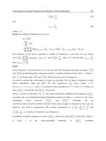
Fig. 1. A highway communication infrastructure (a) and an in-vehicle femtocell (b)
High capacity, Quality of Service (QoS) and data transfer communications are in demand.
Methods to meet these demands include techniques that range from the use of smaller
radius cells and the use of sectorisation, to the most recent use of multiple antennas in
spatial and/or frequency diversity configurations. For these systems it is desirable to have
easy integration and small package antenna units. Multiple Input Multiple Output (MIMO)
Antennas composed of three 120
sectors exploiting frequency diversity gain have been
reported in (Garcia et al., 2008). In the same way, wireless systems devices for the vehicle to
road intercommunication are usually of small profile. A tri-sector configuration antenna to
meet this demand has been reported in (Garcia et al., 2010).
Low cost RoF distribution deployed in-vehicles is of great interest, Fig. 1b. Unlike coaxial,
fibre lines are capable of providing electromagnetic interference free transmissions over the
distance. Centralisation of transceivers to a system backbone might complement with lower
engineering costs, both in deployment and maintenance.
Antennas play a key role in wireless transceivers as they are the last step to radiating energy
into the space. Miniature antennas are required for the in-vehicle application; the prototypes
will have to ensure a good system performance and be platform tolerant.
In the next section, the motorway-to-vehicle wireless communication system, the in-
vehicle wireless communication system including a UWB in-car wireless channel
analysis, and finally the design of an UWB antenna for in-vehicle applications are
introduced.
2.1 Motorway-to-vehicle communication system
In Telematics applications, an autonomous data collection and processing systems can
exploit recent advances in UWB, Worldwide Interoperability for Microwave Access
(WiMAX) and radio fibre technologies to provide data and multimedia services for vehicles
along sophisticated highways (Kerner et al., 2005). Traffic prediction systems are receiving
increased attention and are being evaluated and adopted in a variety of contexts
(Gunter & Grosmann, 2005). Communication between vehicles and vehicle to infrastructure
has also been explored using a range of technologies (Lee & Williams, 2000). Refined
highways hold sophisticated telematics infrastructure that includes fibre, inductive loops
buried, routers, switches and digital video cameras with number plate recognition systems
among others.
An example of a highway sensing and communication infrastructure is depicted in Fig. 1.
Novel Applications of the UWB Technologies
198
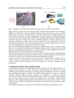
Fig. 2. The Telematics system architecture
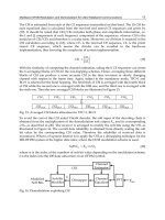
The motorway-to-vehicle wireless communication system is realised using various
components of the system architecture in Fig. 2, the RoF architecture.
In essence, the system architecture comprises a (virtual) central office (CO) which consists of
base station modules (BSM), circulators, attenuators, bidirectional optical transceivers
(BIDI TRX) and wavelength division multiplexers (WDM). Erbium-doped fibre amplifiers
(EDFAs) provide bi-directional amplification to compensate for losses due to long runs of
the single mode fibre (SMF). Optical add drop multiplexers (OADM) provide interfaces
between the fibre and the remote antenna units (RAUs).
The functional view of the RoF system is now detailed. The system employs a high
performance unlicensed 5.470-5.725 GHz WiMAX band directly modulated over a
bi-directional SMF link using remote units composed of three sector antennas
(Garcia et al., 2008) which aims to achieve a better capacity and coverage performance over
micro-cells, and is intended to support around 100 Mbps. The radio frequency (RF) signals
are directly modulated using a distributed feedback laser (DFL) contained in the BIDI TRX.
The signal generated is carried over the downlink SMF to a remote RAU site which converts
this optical signal to an RF signal by positive-intrinsic-negative photodiode with a
transimpedance amplifier (PIN-TIA) receiver with high sensitivity. For uplink transmission,
the wireless signal received from an RAU is amplified, converted into an optical form by a
DFB laser (chosen as an ideal device for SMF and long haul communications), and
transported uplink by the SMF to the CO where another PIN-TIA receiver in BIDI TRX
demodulates the optical signal into the RF.
2.2 In-vehicle communication system
UWB technology has gained huge interest globally due to its potential to deliver high data
rate and spatial capacity, with multipath immunity (Das et al., 2006; Way, 1989) and low
power, low cost design. The deployment of this wireless technology in vehicles will provide
A Telematics System using In-Vehicle UWB Communications
199
mobility and connectivity to a host of passenger devices while reducing significantly the
costs associated with wiring.
In addition, large vehicles can benefit from the use of low cost optical fibre communications.
A RoF system can be used as part of a distributed antenna system (DAS), (with centeralised
control) which supports the deployment of femtocellular access networks at 480Mbps
within airplanes, buses, coaches, cars, lorries, trains, trams and other transport vehicles.
Such a system can assist in the minimisation of radio frequency (RF) inference when
compared to coaxial cable links, simplifies the infrastructure and reduces engineering cost.
A high-level block diagram for the in-car system is depicted in Fig. 3.
Next, a study of a UWB system over RoF in an in-vehicle scenario is described in Section
2.2.1. Experimental results of the radio propagation within the car in a realistic environment
validate the system and are described in Section 2.2.2.
Fig. 3. The in-vehicle distributed antenna system
2.2.1 UWB RoF transmission in-vehicle
A feasibility study of an IEEE 802.15.3a UWB system based on Multi-Band Orthogonal
Frequency Division Multiplexing (MB-OFDM) transmitted over RoF inside a vehicle is
described. The in-vehicle system set-up includes a DV9110 Development Kit (DVK) from
Wisair Ltd and a Renault Extra Van that was used as a base for the experiments. Two
UWB transceivers were placed in the vehicle; one was used as an Access Point (AP) and
the other as fixed/Mobile Equipment (ME). Each transceiver had an integrated
monopole antenna of 2 dBi gain. The transceiver emits a short pulse of output power
80μW (Power Spectral Density PSD of -42 dBm/MHz max) containing the
WiMedia/MBOA Group 1 sub-band (3.168–4.752 GHz) and using a modulated signal
MB-OFDM quadrature phase shift keying (QPSK) at a varying physical data rate
between 53.3 Mbps and 480 Mbps.
The in-vehicle system design is depicted in Fig. 4 which shows the UWB RoF architecture.
A UWB radio at the central unit was directly modulated over an optical signal using a
Vertical Cavity Surface Emitting Laser (VCSEL) and then distributed over a MultiMode
Fibre (MMF) to a remote antenna unit where the transmitted modulated optical signal was
demodulated back to radio using a PhotoDetector (PD) and then propagated by the antenna
Novel Applications of the UWB Technologies
200
into the space. A multimode fibre network was used for the UWB radio distribution due to
the large bandwidth, low loss and the ability of centralisation at a relatively low cost
(Garcia et al., 2005).
Results using Agilent ADS software demonstrate the feasibility of the RoF system. A
waveform generator was used to transmit/receive through the system. It used a signal
spectrum at 1 MHz narrow resolution bandwidth (RBW) filter within a Federal
Communications Commission (FCC) mask. The transmitted and received signals are
depicted in Fig. 5. They overlapped and showed good agreement.
Fig. 4. The complete UWB RoF femtocell
The measured output power was -41.3dBm; this agreed with the maximum UWB Effective
Isotropic Radiated Power (EIRP) allowance and the receiver sensitivity was -79.55 dBm. The
system Transmit (Tx) power budget was measured near 0dBm after compensating for a
power penalty (attributed to optical and RF devices loses) of 8.26dB.
Fig. 5. Transmitted/received UWB MB-OFDM signal
A Bit Error Rate (BER) test evaluated the performance of the system. The transmitter
produced OFDM UWB symbols that a receiver was capable of analysing; with/without
A Telematics System using In-Vehicle UWB Communications
201
multipath over an in-door channel. The resulting test for the down link is depicted in Fig. 6,
where an irrelevant BER difference between a referenced transmitter and the UWB RoF
full-duplex system is observed.
Fig. 6. The system Bit Error Rate (BER)
The results show the feasibility of the RoF system; this would allow extending UWB radio
signals over hundreds of meters distances, well enough for in-vehicle applications.
2.2.2 UWB in-car wireless propagation
Based on the MultiBand technique, the multiband UWB (MB-UWB) splits the spectrum into
sub-bands and uses conventional narrow band techniques, such as Orthogonal Frequency-
Division Multiplexing (OFDM), to transmit the information in each sub-band (Elmirghani et
al., 2006).
In this section, the propagation of a MB-UWB wireless system is studied within the in-car
environment.
Using the same wireless set-up as in Section 2.2.1 without the optical fibre distribution, each
transceiver was connected to a laptop for control and datalogging.
The cell size which is limited by the in-vehicle dimension was 0.9 metres in radius. The
access point was set in the middle of the ceiling of the car as the preferred location in
vehicles (Garcia et al., 2009); this ensures good power distribution and minimises field
exposure to occupants.
The maximum channel path loss (where the antennas are considered as part of the channel)
was measured at 33.53dB at 3.8GHz and the antenna mismatch or de-tuning is best at about
4cm away from the metallic in-car ceiling. A -91.30dBm noise floor was observed and an
Access Point (AP) UWB Development Kit (DVK) power of -43.42dBm (1MHz resolution
bandwidth, RBW) was employed.
Several channel analysis have been reported in (Garcia et al., 2009), this includes a rich
multipath in this application, high reflections, path delay changes in open and closed
environments with a possible Doppler dispersion, and the Inter-Symbol Interference (ISI) for
moving vehicles. A Bit Error Rate (BER) measurement was made to validate the system.
Novel Applications of the UWB Technologies
202
The BER was set up having the Access Point (AP) and Mobile Equipment (ME)
intercommunicating reciprocally with each other. To predict the maximum achievable data
rate at the allowed BER, packets of certain known length were sent over the in-car channel
from the AP to the ME when the vehicle was stationary and then at different vehicle
velocities using the driver closed environment scenario. The received data is analysed and
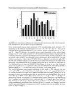
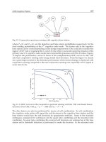
recorded as BER in Figs. 7a and 7b respectively. Throughputs (capacity) for the same set up
are shown in Figs. 8a and 8b. Although there are fluctuations in the BER performance, an
average of 2.5x10
-4
is obtained while the vehicle is stationary and BERs up to 3.2x10
-2
are
measured at a speed of 120km/h.
The vehicle in motion (system closed) affects the BER results. The ISI mainly arising from
high reflections within the small car metallic chamber is conjectured to be aggravated by the
antenna instability due to the mobile vehicle vibration and interaction through the restricted
window area. This is translated into a collection of received variations in the amplitudes and
phases of differently delayed waves caused by further fading and multipath. The
interference of direct path and the reflected waves results in higher BERs.
(a) (b)
Fig. 7. BER as a function of distance (a) and BER as a function of mobility (b).
(a) (b)
Fig. 8. Capacity vs. distance (a) and Capacity vs. mobility (b).
An average of 115Mbps throughput is measured when stationary and up to 102Mbps at a
speed of 120km/h. The vehicle in motion affects the BER results due to the antenna
instability that is created while in motion. There was high multipath in-vehicle, and this, in
A Telematics System using In-Vehicle UWB Communications
203
the moving vehicle, resulted in ISI and caused higher BER measured at higher speeds. In the
same way, a lower data rate was achieved in motion.
3. UWB Antenna for in-vehicle applications
Planar Inverted-F Antennas (PIFAs) are well suited for integration inside vehicles. Their
chasses may contain large steel plates and antennas over ground planes are favoured for
ceiling mounts (Garcia et al., 2009). A UWB PIFA incorporating two shorting posts with
coupling gaps is presented. The antenna operates at the lower UWB band (3.168-4.752 GHz)
with a 3.57:1 VSWR and has a tailored impedance bandwidth and roll-off comparable to a
standard frontend Band Pass Filter (BPF). To bring down unit cost, there has been a drive to
simplify the hardware of UWB systems (Mohammad & Ismail 2008) and hardware could be
further reduced by the adoption of the UWB PIFA proposed here, because the commonly
deployed front-end BPFs would not be required. For the antenna to be implemented in car,
the antenna performance was verified when in close proximity to a large conducting plate.
Additionally, the elimination of the BPF with its associated insertion loss can offer power
savings from the vehicle´s battery especially when stationary.
Fig. 9 depicts the geometry of the UWB PIFA antenna. It consists of two planes, an etched
upper layer (A) and a bottom ground (B) separated by an air substrate (ε
r
≈1).
Fig. 9. Geometry of the UWB PIFA
The A and B planes are capacitively coupled via the two pairs of pins (a & a’ and b & b’).
The dimensions of both posts a & b are 2.9 x 2.9 x 2.9 mm
3
while posts a’ & b’ are 2.9 x 2.9 x
1.45 mm
3
. Coupling between planes A and B is achieved across the gaps in the posts.
The antenna is fed at the upper plane A using the inner core (0.51 mm) of a 50Ω rigid coax
cable with a total diameter of 2.16mm and 62mm length. The outer shield of the cable is
Novel Applications of the UWB Technologies
204
attached to a grounding strip, D, electrically connected to B. The total volume of the antenna
is 19.58 x 15.75 x 5.53 mm
3
. The maximum dimension is smaller than 0.21λ at the lowest
frequency of operation.
A simulated parametric study of the capacitive gap is reported in (Garcia et al., 2010b)
where decreasing the gap between a and a' (or b and b') tended to improve the band-notch
depth and impedance roll-off. Therefore, adjusting the gap capacitance of the electrically
unconnected shorting posts allows a BPF like characteristic to be defined. An optimum
length value of a = b = 2.9 mm and, a' = b' = 1.45 mm was found to give a band-notch at
5.5GHz, a return loss (RL) of -5dB, roll-off of 0.18 and 0.03 dB/MHz and a -5dB S11
fractional bandwidth of 40%. The optimal value of the gap corresponds to 1.18mm.
Fig. 10. The UWB PIFA antenna
The reflection coefficient of the UWB antenna is shown in Fig. 10 compared to a standard
frontend BPF (RFlambda, n.d.). Compared to the commercially available BPF (2441MHz
pass-band rejection and 2dB insertion loss; roll-offs of 0.050dB/MHz and 0.031dB/MHz for
the lower and upper bands respectively), the UWB antenna has a lower 1108MHz pass-band
rejection and improves the roll-offs to 0.024dB/MHz and 0.030dB/MHz.
An antenna having a VSWR of 3.57 (5dB RL) can be calculated to present an equivalent
mismatch loss of 1.65dB (Kraus & Marhefka, 2001). Therefore, if the BPF and its associated
mismatch loss of 2dB was removed, then there will still be an overall reduction in loss of
0.8dB.
The measured 5dB return loss bandwidth of the proposed PIFA is 42.15% for the
3.168-4.860 GHz FCC UWB. To investigate the effect of attaching the antenna to a large
conducting plate in a car chassis, a larger ground plane of dimensions 510 x 800 x 0.75 mm
3
was placed ¼ wavelength below the PIFA. Fig. 10 shows the S11 response.
A Telematics System using In-Vehicle UWB Communications
205
The far-field radiation patterns of the antenna including the large plane in polar form
(measured at 4.752 GHz) are depicted in Fig. 11. The patterns are essentially directional,
presenting a 120
half power beam-width (HPBW) and 1.53/1 front-to-back ratio in the
H-azimuth plane and similar value for the E-elevation. A gain of 7.11dBi was measured
with the E plane present.
Fig. 11. Radiation patterns of the antenna including the large ground plane
Novel Applications of the UWB Technologies
206
4. Conclusion
This chapter has introduced new techniques and methodologies to support the cost effective
growth of mobile telephony and the tremendous increase in Internet data traffic in
Telematics for the delivery of enhanced services to highways users.
A Telematics system has been described based on a high performance WiMAX spectrum
using an unlicensed band (5.470-5.725 GHz) and recent developments in RoF systems as a
base for the delivery of wireless communications to motorway-to-vehicle applications. This
approach results in a relative low cost deployment and maintenance, extends the radio over
long distances and delivers peak rates of at least 1 Gbit/s to fixed users and 100Mbit/s to
mobile users over micro-cells.
Cost-effective while efficient narrow band tri-sector antenna units have been assessed for
Intelligent Transport Systems (ITS) in the presented highway scenario. The antennas served
the WiMAX standard over full-duplex bi-directional optical links (Garcia et al., 2008). These
antennas seem to be reasonably proficient for use in ITS due to their potential higher gains
and reduced spatial limitations. The low VSWR performance achieved by the use of these
narrow band antennas can improve the system link budget, which is translated into a
relatively higher coverage/throughput.
The Robustness to multipath interference offered by the unlicensed lower band
(3.168-4.752 GHz) UWB communication is to be exploited for in-vehicle communications.
Within this work a promising low cost RoF link to extend the UWB radio over relatively long
distances (i.e.: trains, trams and airplanes) has been introduced. The transmission was assessed
using a relatively inexpensive multimode RoF link. The transmission network was capable of
providing high data rates of 400-480Mbps at picocells of about a metre radius with
inconsiderable SNR degradation performance over fibre links of several hundred of meters.
In addition, a wireless propagation of UWB radio inside a vehicle is analysed. The analysis
of the UWB radio channel in-vehicles demonstrates that UWB is a very suitable and
promising technology for transmission networks able to provide high data rates of 400Mbps
within cars. Path loss was not of a significant level due to the short ranges that are
encountered within cars. However, the main attenuation might perhaps be due to
shadowing effects. High data rates were achieved in closed environment scenarios (Garcia et
al., 2009). As many new cars include air conditioning, it is not unreasonable to expect the
environment to be closed for the majority of the time.
A UWB antenna design example for an in-vehicle application has been introduced. The
results indicate that the presented antenna works satisfactorily in the unlicensed UWB band
and that the antenna element can be mounted on a large ground plane without degrading its
performance. Owing to the low volume of the design it can be easily integrated inside
vehicles in close proximity to the body.
5. Acknowledgment
This work was partially funded by the European Union.
6. References
Biagi, M. & Baccarelli, E. (2003). A simple multiple-antenna ultra wide band transceiver
scheme for 4th generation WLAN, IEEE 58th Vehicular Technology Conference,
pp. 1903 – 1907, Volume 3, Orlando, Florida, USA, 2003.
A Telematics System using In-Vehicle UWB Communications
207
Das, A., Nkansah, A., Gomes, N. J., García Zuazola, I. J., Batchelor, J. C. & Wake, D. (2006).
Design of Low Cost Multimode Fiber-Fed Indoor Wireless Networks, IEEE
Transactions on Microwave Theory and Techniques, pp. 3426-3432, Vol.54, No.8,
August 2006.
Elmirghani, J.M.H., Badic, B., Li, Y., Liu, R., Mehmood, R., Wang, C., Xing, W., García
Zuazola, I.J. & Jones, S. (2006). IRIS: An Intelligent Radio-fibre Telematics
System, proc. of 13th ITS World Congress and Exhibition in London, UK, 8-12
October 2006.
FCC - Federal Communications Commision, (2002). First Report and Order on Ultra-Wideband
Technology, fCC 02-48, Washington, DC, 22nd April, 2002.
García Zuazola, I.J., Batchelor, J.C., Langley, R.J., Das, A., Nkansah, A., Wake, D. & Gomes,
N.J. (2005). Photonic Antenna Units containing Bi-directional Amplification for
TDD and FDD in Picocell Systems, Proc. LAPC Conference, pp. 217-220,
Loughborough, UK, April 2005.
García Zuazola, I.J., Elmirghani, J.M.H. & Batchelor, J.C. (2008). WiMAX Antennas for
Intelligent Transport Systems communications, Proc. LAPC Conference, pp. 133-136,
Loughborough, UK, 17-18 March, 2008.
García Zuazola, I.J., Elmirghani, J.M.H. & and Batchelor, J.C. (2009). High-speed ultra-wide
band in-car wireless channel measurements, IET Communications., pp. 1115–1123,
Volume 3, Issue 7, 2009.
García Zuazola, I.J., Batchelor, J.C. & Elmirghani, J.M.H. (2010). Sectorized WIMAX Antenna
for future Vehicular Communications Systems, Microwaves, Antennas & Propagation,
IET, pp. 210 – 218, Volume 4, Issue 2, Feb. 2010.
García Zuazola, I.J., Batchelor, J.C., Elmirghani, J.M.H. & Gomes, N.J. (2010b). UWB PIFA
Antenna for simplified transceivers, Electronics Letters, pp. 116–118, Volume 46,
Issue 2, January 2010.
Gunter, Y. & Grosmann, H.P. (2005). Usage of Wireless LAN for Inter-Vehicle
Communication, Proceedings of the 8th International IEEE Conference on Intelligent
Transportation Systems, pp. 296-301, Vienna, Austria, September 13-16,
2005.
Kerner, B. S., Rehborn, H., Aleksi, M. & Haug, A. (2005). Traffic Prediction Systems in
Vehicles, Proceedings of the 8th International IEEE Conference on Intelligent
Transportation Systems, pp. 251-256, Vienna, Austria, September 13-16,
2005.
Kraus, J. D. & Marhefka R. J. (2001). Antennas for all applications, 3rd edition, McGraw-Hill,
ISBN 0072321032, Boston, 2001.
Lee, K.F. & Williams, D. B. (2000). A Space-Frequency Transmitter Diversity Technique for
OFDM Systems, IEEE Globecom, pp. 1473-1477, Volume 3, San Francisco, Nov.
2000.
Mohammad, N.H. & Ismail, W. (2008) System-level integration and simulation of ultra
wideband receiver front-end, Communications, Propagation and Electronics, MIC-CPE
Mosharaka International Conference, pp. 1-6, Jordan, 6-8 March 2008
RFlambda (n.d.) Available from: www.rflambda.com
Novel Applications of the UWB Technologies
208
Way, W. I. (1989). Subcarrier multiplexed lightwave system design considerations for
subscriber loop applications, Journal of Lightwave Technology, pp. 1806–1818, vol. 7,
no. 11, November 1989.
Part 3
Novel UWB Applications
in Cognitive Radio Systems
0
UWB Cognitive Radios
Sithamparanathan Kandeepan
1,2
, Gianmarco Baldini
3
and Radoslaw Piesiewicz
4
1
RMIT University, Melbourne
2
CREATE-NET, Trento
3
Joint Research Center, European Commission, Ispra
4
Wroclaw Research Center, EIT+, Wroclaw
1
Australia
2,3
Italy
3
Poland
1. Introduction
In this chapter we present UWB communication as a potential candidate for cognitive radio
technology. Cognitive radios are intelligent radios that could adopt itself by sensing and
learning the radio environment and optimize its transmission strategies to maximize the
utilization of the scarce radio resources such as the radio spectrum. This has been motivated
by the radio regulatory bodies around the world (EC, 2007; FCC, 2003) to utilize unused
radio spectrum known as white space in the spatio-temporal domain. In the recent years
UWB communication has emerged as a potential candidate for the CR technology due to
its ability to share the spectrum with others for short range wireless communications. In
this context we present the concept of cognitive radios and the necessary techniques to
adopt UWB as cognitive radios in this chapter. Especially, we enhance on the fundamentals
of cognitive radios and spectrum sensing which enable the UWB radio to learn the radio
environment. We also touch upon other cognitive radio related topics that are related to UWB
communications such as dynamic spectrum access, interference mitigation and localization
techniques. Furthermore, we present some potential applications for the use of UWB based
cognitive radios which are derived from the European Union funded projects EUWB (EUWB,
2008) which is one of the biggest UWB projects that the world has seen so far, and the
C2POWER project (C2POWER, 2010) which is related to energy efficiency in short range
wireless communications with the use of cognitive radios. In this chapter we do not consider
the technological aspects related to the use of cognitive radios for energy efficiency but only
consider the use of cognitive radios for dynamic spectrum access. However, at the end of
the chapter we present a scenario for the use of cognitive radios for energy efficiency derived
from (C2POWER, 2010).
In the material presented in this chapter we mainly consider the high data rate UWB
radios based on the Multi-Band Orthogonal Frequency Division Multiplexing (MB-OFDM)
technique following the Wimedia specifications (Wimedia-PHY, 2009). The OFDM based
transceiver design makes it feasible for the UWB radio to sense the radio environment
and dynamically change the transmission parameters accordingly. This makes the UWB
11
2 Will-be-set-by-IN-TECH
radios much more attractive and to suit cognitive radio technology that require having
intelligence and adoptability in the radio itself. Moreover, the low transmit power in UWB
communications also makes it feasible to have secondary user access to the spectrum without
interfering with the primary users of the spectrum. The concepts of secondary users and
primary users are treated subsequently in this chapter.
2. Cognitive radio fundamentals
The term cognitive radio was coined by Joseph Mitola (Mitola, J. & Maguire Jr. G.) considering
ideal context aware radios with embedded intelligence. Mitola’s vision of cognitive radios
spans across all the layers of the communication protocol stack emphasizing on the need
for optimum utilization of the radio resources by adopting its transmission policies and
strategies. The adaptation of the local policies is based on sensing and learning the
environment or by being informed about the radio environment by an information broker
in the network. Haykin (Haykin, S. 2005) then adopted Mitola’s ideal cognitive radio
concept to wireless communications by defining the corresponding communications and
signal processing problems associated with cognitive radios in the lower layers of the protocol
stack. Here we present the fundamentals of cognitive radios explaining the cognitive engine
and the cognitive cycle as described by Mitola and Haykin. We present the concept of white-
space in the spatio-temporal domain in regards to spectrum utilization and the underlay and
overlay technologies for dynamic spectrum access.
2.1 Spectrum classification in a broader sense
First let us classify the spectral usage in the spatio-temporal domain. By computing the power
spectra of the received radio stimuli at a particular point and time one could broadly classify
the spectra into three types (Haykin, S. 2005), as given below.
Black Spaces: spectra occupied by high-power ’local’ interferers.
Gray Spaces: spectra occupied partially by low power interferers.
White spaces : spectra free of radio frequency interferers except for ambient natural and man-
made noise.
Fig. 1. The evolution of ’spectrum holes’ in the spatio-temporal domain
One could clearly see that the above classification is a function in the spatio-temporal domain.
For example, ’black’, ’gray’ and ’white’ spaces could appear and disappear back and forth
at a particular location over time. Therefore it is necessary to sense and learn the radio
environment in order to maximize the spectral usage opportunistically. In other words
212
Novel Applications of the UWB Technologies
UWB Cognitive Radios 3
detecting ’spectrum holes’ as it is termed is quite crucial for dynamic spectrum access. Figure-
1 depicts the concept of ’spectrum hole’ evolution in the spatio-temporal domain.
2.2 Spectrum sharing in cognitive radio networks: ’Underlay’ and ’Overlay’ techniques
With cognitive radio technology the concept of ’primary users’ and ’secondary users’ of the
spectrum are developed. The primary users are the incumbent users with the exclusive rights
to use the spectrum at anytime and the secondary users, also known as the cognitive radio
users, are the users that use the spectrum without interfering with the primary users. There
are basically two spectrum sharing techniques considered for cognitive radio networks for
maximizing the spectral efficiency between the primary and the secondary users. First is the
’spectrum underlay’ technique and second is the ’spectrum overlay’ technique.
Fig. 2. Spectrum sharing in cognitive radio networks, with (a) overlay and (b) underlay
sharing techniques.
In the ’spectrum underlay’ method the secondary users can utilize the spectrum
simultaneously with the primary users without exceeding a predefined interference level to
the primary users. Secondary users in this case can share the spectrum such that the total
interference power from the secondary users to the primary users are controlled below the
interference limit set by the relevant regulatory authorities. The characterization of such
interference limit is given in the next subsection. Figure-2 depicts the concept of spectrum
underlay technology. UWB radio technology due to the low powered transmissions in the
ultra wide band frequency range is therefore a potential candidate for deploying spectrum
underlay technology for spectral sharing. Using the low powered transmissions and making
sure that the interference limit is not exceeded UWB radios can potentially share the spectrum
with the primary users and coexist.
In the ’spectrum overlay’ method the cognitive radios can identify the spectrum holes in the
spatio-temporal domain and opportunistically utilize them by giving higher priority to the
primary users. Whenever a primary user is not using the spectrum secondary users (cognitive
radios) are allowed to transmit however when a primary user is detected in that particular
band then secondary users need to immediately vacate the band by stopping transmitting in
that particular band. In this sense spectrum sensing and primary user detection become a
crucial functionality for reliably detecting the primary users in the environment in the spatio-
temporal domain. Figure-2 depicts the concept of spectrum overlay technology at a particular
time in some space. The MB-OFDM based UWB technology is considered as a potential
candidate for spectrum overlay technology for spectrum sharing by inherently making use
of the OFDM transmission technique. By using OFDM, UWB devices can dynamically turn
on and off the corresponding subcarriers depending on whether any primary users exist or
213
UWB Cognitive Radios
4 Will-be-set-by-IN-TECH
not in a particular band in the environment. In other words the transmission spectrum of
UWB radios can be sculpt according to the presence of the primary users in the respective
frequency bands in the environment.
2.3 The interference temperature limit
The interference temperature T
I
is a measure of the interference power level due to wireless
transmissions at a particular location as defined by the FCC in (FCC, 2002). The interference
temperature follows a similar definition as to the thermal noise temperature in receivers. It is
well known that the thermal noise power P
n
in receivers is given by (Sklar, B.),
P
n
= kT
N
B (1)
where k
= 1.38 ×10
−23
is the Boltzmann’s constant, B (Hz) is the receiver operating frequency
bandwidth and T
N
(in degrees Kelvin unit) is the noise temperature. Likewise the total
interference power P
I
due to the transmissions of wireless devices and natural interferences
at a particular point in space can be characterized by,
P
I
= kT
I
B (2)
The interference temperature limit T
max
I
therefore is an upper limit on the value of T
I
that
can be used to control and limit the interference in the radio environment. Such limits for the
interference temperature can be used to enable the underlay spectrum sharing technique by
coordinating or policing the interference level in the environment generated by the secondary
users to the primary users.
2.4 The cognitive cycle
The cognitive cycle is the term describing the activities involving the intelligence of the radio
device such as sensing, learning and adopting. In (Mitola, J. & Maguire Jr. G.), Mitola had
presented a generic cognitive cycle that corresponds to his view of ideal cognitive radios.
By adopting this model, Haykin then presented a similar cognitive cycle model in (Haykin,
S. 2005) by mainly describing the PHY and MAC layer aspects of the radio device considering
the communications and signal processing functionalities. Here we explain both the cognitive
cycles described by Mitola and Haykin.
Fig. 3. Cognitive Cycle described by (Mitola, J. & Maguire Jr. G.)
214
Novel Applications of the UWB Technologies
UWB Cognitive Radios 5
Figure-3 depicts the cognitive cycle described by Mitola. In the figure the radio observes and
senses the external world and orients itself according to the internal policies and plans before
making a decision on how to act upon that situation. Once the decision is made the radio then
acts accordingly. Then in the next and the consecutive cycles it goes through a similar process
until it decides not to operate. The cognitive radio learns from the observations as shown in
the figure. The core of the cognitive cycle that lies inside the radio is known as the cognitive
engine.
The equivalent cognitive cycle presented by Haykin is depicted in Figure-4. In this figure,
the corresponding signal processing and communications functionalities associated with
the radio is presented within the cognitive engine. As shown in the figure, the cognitive
radio observes the radio environment using the sensed radio stimuli and creates a radio
environment map of the potential radios in the environment considering the spatio-temporal
usage of the frequency bands. This information is then used together with the channel state
estimation by the transmitter to adopt its transmissions accordingly.
Fig. 4. Cognitive Cycle corresponding to the communications and signal processing aspects
in the radio, as described by (Haykin, S. 2005)
The cognitive engines presented in Figure-3 and Figure-4 are only the conceptual ones which
include the basic functionalities required for the radio to have intelligence. The spectrum
sensing functionality helps the radio to observe the radio environment, and is one of the
hot topics in the field of cognitive radios. Spectrum sensing is covered later in Section-5.
The radio environment map is then created with the use of spectrum sensing information
and the radio-localization functionality (if available) of the cognitive radio. Localizing a
radio in the environment is not always feasible given the fact that the localization task needs
to be performed blindly. Once the cognitive radio nodes have a good understanding of
the radio environment it would then perform power control with appropriate interference
mitigation techniques in the spatio-temporal domain to transmit its data. Furthermore, other
functionalities also can be added into the cognitive engine depending on the applications and
any specific requirements appropriately.
215
UWB Cognitive Radios
6 Will-be-set-by-IN-TECH
3. Dynamic spectrum access
The radio spectrum can be utilized by considering various access strategies, methodologies
or policies. In this section we provide a quick background on the spectrum access models to
explain how cognitive radios are used for dynamic spectrum access. Spectrum access models
can be classified as command and control model, exclusive-use model, commons model and
the shared model (Hossain, E. et. al.). In the shared use model the secondary user of the
spectrum will opportunistically access the spectrum without interfering with the primary user
of the spectrum, in the exclusive use model the unlicensed secondary user can be granted
access to the spectrum by the licensed primary user, and in the commons model the secondary
user can access the spectrum without any restrictions. In Figure-5 we present a taxonomy of
the different spectrum access models.
Fig. 5. Classification of spectrum access models
For a detailed description of the different access models the reader is referred to (Hossain,
E. et. al.). In the previous section we briefly described the access model that is of interest to us
which is the shared spectrum access model that includes the spectrum underlay and overlay
techniques. In the ’shared’ model the concept of primary and secondary users of the spectrum
are derived and the spectrum can be shared simultaneously between the primary and the
secondary users of spectrum. The primary users are the incumbent users of the spectrum
however the secondary radios also can use the spectrum. In this case the secondary radios
need to make sure that they do not interfere with the primary radio transmissions, and as long
as the interference constraint is met the secondary users can use the spectrum transparently
to a primary user.
4. UWB as cognitive radio, and coexistence
As described previously cognitive radio nodes require intelligence and self adoptability in
order to dynamically adopt its strategies based on the time varying radio environment. In this
section we see how UWB devices can suit such requirements and be considered as a potential
candidate for cognitive radio technology. Based on MB-OFDM transmission, Figure-6 depicts
216
Novel Applications of the UWB Technologies
UWB Cognitive Radios 7
how UWB radios could be used as secondary radios based on cognitive radio technology for
sharing the spectrum with the other users. In this section we further describe how the UWB
radios can be considered to adopt both underlay and overlay spectrum sharing models.
Fig. 6. Intelligent spectrum sharing mechanism based on underlay and overlay policies by
UWB radios using cognitive radio technology
As we know there exist many radio technologies in the UWB frequency range operating in
the licensed as well as the unlicensed frequency bands. The UWB radios therefore need to
coexist with all the radios in the frequency range which makes UWB as a potential candidate
for cognitive radio technology which maximizes the usage of the scarce spectrum. In this
section we further consider the coexistence of various spectrum users in the UWB frequency
range with the MB-OFDM based UWB radios. In particularly, we discuss the policies and
requirements for the UWB radios to coexist with the other radios and utilize the spectrum as
a secondary user considering both underlay and overlay spectrum access methods. Power
controlling with the concept of interference temperature limit, spectrum sculpting together
with detect-and-avoid (DAA) techniques are some of the strategies used by UWB radios in
order share the spectrum with the primary users. Below we provide some background on
spectrum sculpting and power control in UWB radios in the context of spectrum sharing, and
later we present detect-and-avoid technique in detail.
4.1 Spectrum sculpting
For the UWB radios to share the spectrum with the primary users using the overlay method
it needs to shape its transmission spectrum in such away that the primary users are not
interfered. Spectrum sculpting techniques are used for shaping the spectrum in UWB radios
(Wang, Z.; Yamaguchi, H.). The two most common spectrum sculpting methods are the
spectrum shaping in time domain using shaped pulses and spectrum shaping in the frequency
domain using tone nulling (in OFDM systems). The time domain method in general may
not be possible to shape the spectrum in all the cases, the frequency domain tone nulling
method on the hand can provide better performances in terms of shaping the spectrum. The
tone nulling technique can cause spectral overshoots in the transmission band and hence
various derivatives of this method are also considered such as enhanced active interference
217
UWB Cognitive Radios
8 Will-be-set-by-IN-TECH
cancelation as proposed in (Wang, Z.). The example shown in Figure-6 clearly depicts how the
spectrum sculpting technique is used in UWB radios in order to coexist and share the radio
spectrum with the primary user radios in the environment.
4.2 Power control
Power control in wireless and mobile communications is a well studied topic for more than
twenty years. It has attained more attention in the recent years for potential spectrum sharing
in cognitive radio networks. Traditionally power control was considered for maximizing
the transmission rate with fare-scheduling without degrading the QoS of the other users in
the environment. In a similar context power control is also considered for cognitive radio
networks as presented in (Gu, H.; Radunovic, B.; Xing, Y.; Zhang, L.). Here we briefly explain
the concept on power control for dynamic spectrum sharing with underlay technology in
cognitive radio networks by having the total interference power as a constraint.
Suppose P
I
is the interference power limit corresponding to the interference temperature T
I
as explained in (2). If there exist K number of cognitive radios in the environment sharing the
spectrum with the incumbent users, then the total interference caused to the l
th
primary user
is given by,
I
l
=
K
∑
k=1
h
kl
P
k
(3)
where, P
k
is the transmitted power from the k
th
cognitive radio node, and h
kl
is the channel
gain from the k
th
cognitive radio node to the l
th
primary user in the environment. In order to
comply with the interference regulatory level, for the interference caused from the secondary
users to the primary users, the following constraint should be met,
I
l
=
K
∑
k=1
h
kl
P
k
≤ P
I
∀l (4)
The cognitive radio nodes on the other hand would like to achieve the highest possible
transmission rate which is related to the received signal to interference ratio γ
km
at the m
th
secondary receiver where m = 1 K and m = k,givenby,
γ
km
=
h
km
P
k
∑
K
u
=1,u=k,m
h
um
P
u
+ σ
2
m
(5)
where, h
km
is the channel gain from the transmitter k to the intended receiver m, h
um
is the
channel gain from the transmitter u to the unintended receiver m, P
u
is transmitted power
from the transmitter u,andσ
2
m
is the receiver noise power at the receiver node m.Thenin
order for the secondary communication pair
{k, m} to have the best possible transmission
rate, considering the constraint in (4), the simplest optimization strategy for power control is
given by,
ˆ
P
k
= max
P
k
γ
km
,suchthatI
l
≤ P
I
(6)
It might be difficult to measure the interference power at the primary user node unless the
primary user cooperates. In such situations there can be a power controller or a monitor
serving the purpose of controlling the power by measuring the total interference power at
some central location. In literature one could find various cooperative and distributed power
controlling methods using game theoretic approaches which we do not cover in this chapter.
218
Novel Applications of the UWB Technologies
UWB Cognitive Radios 9
5. Spectrum sensing
Spectrum sensing is one of the crucial functionalities of a cognitive radio in order to learn
the radio environment. Various spectrum sensing techniques exist (Kandeepan, S. et. al;
Yucek, T. and Arslan,H.) and in general could be classified as 1) energy based sensing, 2)
cyclostationary feature based sensing and 3) matched filter based sensing. The energy based
sensing is the simplest method to sense the environment in a blind manner, the cyclostationary
based sensing may require some information about the spectral-user signal characteristics,
and the matched filter based sensing requires the complete information of the spectral-user
signal. In this section we elaborate in detail on the various spectrum sensing techniques
and their related detection performance for MB-OFDM based sensing. Moreover, we present
collaborative sensing techniques in order to address the ’hidden node problem’.
Let us provide some background on spectrum sensing prior to presenting the related
techniques. Spectrum sensing and detecting the presence of a radio in the environment
is treated as a classical statistical detection problem (Kay, S.). We define the two binary
hypotheses H
0
and H
1
to indicate the absence and the presence of the primary users in the
environment respectively. In the discrete signal domain this could be represented as,
r
(n)=
ν
(n), H
0
s(n)+ν (n), H
1
(7)
where ν
(n) is the additive Gaussian channel noise and s(n) is the received signal. If the test
statistic that is used for the detection is given by ξ
(r(n)), which is a function of the sensed
signal r
(n) with n = 1,2 N, then the detection criteria is given by,
d
=
0; ξ
< λ
1; ξ
≥ λ
(8)
where, λ is known as the detection threshold. The probability of detection and the probability
of false alarm are then defined as,
P
D
= Pr[d = 1|H
1
] (9)
P
FA
= Pr[d = 1|H
0
] (10)
The probability of miss detection on the other hand is defined by Pr
[d = 0|H
1
],andthusis
given by P
M
= 1 − P
D
. In general the detection threshold λ is chosen in order to trade off
between the detection and false alarm probabilities. Different criteria can be used in order to
find the optimal threshold which is a well treated topic in the literature of statistical detection,
which we do not present in this chapter. In the subsequent sections we provide various ways
to derive the test statistic ξ used for the detection of primary users.
5.1 The hidden terminal problem
Prior to presenting the spectrum sensing techniques we present why spectrum sensing is
treated as an important topic in cognitive radio literature. We mentioned that the detection
performance is characterized by the probability of successfully detecting the radio and the
probability of false alarm. In cognitive network applications the regulatory bodies are quite
strict on secondary nodes causing any interference to the primary users, in this sense the
primary users need to be reliably detected by the secondary users with a high detection
probability (close to 100% or P
D
1). The detection probability usually depends on the
219
UWB Cognitive Radios
10 Will-be-set-by-IN-TECH
signal to noise ratio of the received signal, the received signal power depends on how far
the transmitting node is from the sensing node characterized by the path loss. Moreover,
channel fading is also a factor that affects the received signal power. In this sense, radio nodes
(primary users) closer to the cognitive radios are easily detected with a higher probability of
detection compared to the radio nodes that are further away from the cognitive radios. When
the primary user radios are not detected by the cognitive radio nodes they do not appear in
the radio environment map created by the cognitive radio nodes, and hence the primary user
nodes become hidden to the cognitive radio nodes. This is known as the ’hidden terminal
problem’. Figure-7 depicts a typical hidden terminal problem scenario. In the figure, CR-
1 is unable to detect the PU and hence the PU node is hidden from the CR-1 node. The
hidden node problem can create interference from the secondary nodes to the primary nodes
and hence therefore harming the communication rights of the primary radios in the allocated
band and violating the regulatory requirements. The hidden terminal problem also can harm
the performance of secondary user communications interfered by the primary user in this
case. Therefore, various spectrum sensing and detection techniques are considered to solve
the hidden terminal problem to increase the detection probability for detecting the primary
users in the environment.
Fig. 7. An example of the hidden terminal problem, where the PU node is hidden from CR-1.
5.2 Spectrum sensing with energy detection
The energy detector is the simplest spectrum sensing method for detecting primary users in
the environment in a blind manner (Urkowitz, H.). It is computationally efficient and also
be used conveniently with analog and digital signals (or in other words at the RF/IF stages
or at the base band). It also has a well known drawback in the detection performance when
the noise variance is unknown to the sensing node. When the signal to noise ratio is very
low the knowledge of the noise power can be used to improve the detection performance of
the energy detectors. In energy detectors, the energy of the received signal is computed over
a time period T or equivalently over N samples in the discrete domain and used as the test
statistic, where T
= NT
s
and T
s
is the signal sampling period. The test statistic at the base
band considering the complex envelope of the received signal is therefore given by,
ξ
=
t
2
t
1
r(t)
˜
r
(t)dt (11)
where,
˜
r
(t) is the complex conjugate of r(t). The signal to noise ratio (SNR) is then defined
based on the received signal s
(t) for t
1
< t ≤ t
2
for some t
1
, t
2
∈ R
+
,givenby,
ρ
=
1
σ
2
i
[t
2
−t
1
]
t
2
t
1
s(t)
˜
s
(t)dt (12)
220
Novel Applications of the UWB Technologies
UWB Cognitive Radios 11
Note that based on the transmission pattern of the primary user the instantaneous signal to
noise ratio would vary, here however we assume ρ to be a constant. For the discrete signal on
the other hand, the energy based test statistic is given by,
ξ
≈ T
s
N
−1
∑
n=0
r[n]
˜
r
[n] (13)
where, N is the total number of complex samples and is also known as the time-bandwidth
product (Urkowitz, H.). Note that in (12) there are essentially N number of real component
samples and N number of imaginary component samples. Considering the discrete domain
test statistic the detection criteria is then given by,
d
=
0; ξ
< λ
1; ξ
≥ λ
(14)
In order to compute the detection probability and the false alarm probability we consider the
distribution of the test statistic ξ. The energy based test statistic ξ follows a non-central and a
central chi-sqaure distribution under H
0
and H
1
respectively with 2N degrees of freedom.
Using the distributions of the test statistic under H
0
and H
1
we can derive the detection
probability and the false alarm probability using equation (9) and (10) and in closed form
expressions as (Dingham, F.,F.),
P
D
= Q
N
(
2Nρ,
√
λ) (15)
P
FA
= Γ(N, λ/2) (16)
where, Γ
(a, b)=
1
Γ(N)
∞
b
u
a−1
exp(−u)du is the regularized upper incomplete Gamma
function, Γ
(.) is the Gamma function, Q
N
(a, b)=
∞
b
u
N
exp(−(u
2
+ a
2
)/2)I
N−1
(au)/a
N−1
du
is the generalized Marcum Q-function, and I
N−1
(.) is the modified Bessel function of first kind
with order N
−1.
Let us look at some results for the detection performance of the energy detector in the additive
Gaussian noise channel by plotting the complementary receiver operating characteristics (C-
ROC) curve. The C-ROC depicts the probability of false alarm in the x-axis and probability
of miss detection in the y-axis. Figure-8 shows the C-ROC curves for the energy detector
for various values of signal to noise ratio levels ρ.Asweobservefromthefigure,the
detection performance improves with increasing values of ρ by achieving lower miss detection
probabilities for lower false alarm probabilities when ρ increases. Figure-9 on the other hand
shows the C-ROC curves for various values of N, and again we observe that the detection
performance improves with increasing values of N.
Note that the analytical results presented here do not consider the wireless channel effects
such as fading or shadowing, authors in (Dingham, F.,F.) and (Atapattu. S., et. al.) have
presented closed form expressions for the detection probability for the energy detector
considering various wireless channels which we do not cover in this chapter.
5.3 Spectrum sensing with cyclostationary feature detection
The cyclostationary feature analysis is a well developed topic in the literature of signal
processing (Gardner, W.). In wireless communications, depending on the modulation type,
data rate and carrier frequency etc. the transmitted signals show very strong cyclostationary
features, especially when excess bandwidth is utilized. Therefore identifying the unique set
221
UWB Cognitive Radios