Nuclear Power Operation Safety and Environment Part 5 pdf
Bạn đang xem bản rút gọn của tài liệu. Xem và tải ngay bản đầy đủ của tài liệu tại đây (947 KB, 30 trang )
Low Power and Shutdown PSA for the Nuclear Power Plants with WWER440 Type Reactors
109
estimate of the effective dose that could be avoided by implementing a particular
countermeasure, the lower and upper emergency reference levels are defined. Below the
lower level, introduction of the countermeasure would not be justified because of the harm
that it would cause. The upper level is the dose level at which every effort should be done to
introduce the countermeasure, except in exceptional circumstances. It is set at ten times the
dose of the lower level.
The lower and upper levels for sheltering are a dose of 5 mSv and 50 mSv respectively. For
evacuation, they are 50 mSv and 500 mSv. These are higher than the recommended dose
limit for routine exposure, which is 1 mSv per year for the public. This is because the dose
levels are not intended to represent the boundary between what is ‘safe’ and what is
‘unsafe’, but to represent an acceptable balance between the harms and benefits of an action.
In case of fission product release the release is large if more than 1% caesium is released to the
environment from the core inventory. It can correspond to the dose of 50 mSv/y for the public.
Large early release is a release to the environment before implementation of required
countermeasure (before evacuation). For the purpose of the WWER440 units it is considered
that the evacuation can not be performed until 10 h from the beginning of the accident. The
release until 10 h is the early release.
For the groups G0, G1 a G2 the Large early release frequency (LERF) is given as sum of
frequencies of the following source term categories: STC7 + STC9 + STC13 + STC16 + STC17.
For group G3 the LERF is given by STC14 and STC15 (the reactor vessel is open, the
containment is open). For group G4 the LERF is given by STC8 (the spent fuel pool is
outside the containment).
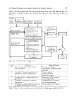
3.7 Results
The source term category 14 for group G3 is presented in Table 4 for illustration of the
results. The fission product groups Xe, I and Cs are presented in table with the
corresponding frequency.
Source term
category
Frequency
1/y
Beginning of
the release
Xe
[%]
I
[%]
Cs
[%]
14 4.08E-6 Early 94.8307 86.0377 83.8331
Table 4. The source term categories for group G3
The risk of fission product release from the spent fuel pool is very small in operating mode
7. The source term category frequency is 3.0E-9/y. However, the quantity of fission products
in the source term is extremely high because the pool is located outside the containment and
the spray system has no impact on the fission products which can be released into the
environment. The fuel inventory is also higher in comparison with the core inventory.
The LERF for each group G0-G4 is less than 1.0E-5/y. The requirement of the Nuclear
Regulatory Authority is met.
4. Conclusion
The level 1 shutdown risk of the WWER440/V213 plants presented in the form of CDF was
higher than the risk coming from the full power operation. Safety measure were
implemented which significantly decreased the CDF. After implementation of the proposed
Nuclear Power – Operation, Safety and Environment
110
changes the same level of risk is achieved for shutdown operating modes as for the full
power operation.
The changes in the limiting condition of operation are the most important from the
shutdown risk reduction point of view. In operating mode 5 and 6 only one train of safety
system was required to be available. Now the limiting conditions of operation require the
availability of safety system trains to the maximum extent possible. It was also
recommended that the preventive maintenance for all three trains of safety systems should
be done only in operating mode 6, when there is high water level in the reactor refuelling
cavity and more than 30 h are required to core uncovery after loss of residual heat removal.
Symptom-based emergency operating procedures (SB EOPs) for shutdown operating
modes, developed by Westinghouse and implemented in the Slovak NPPs, also significantly
reduce the risk.
In addition, risk reduction factor of automatic operation of low pressure safety injection
pumps during shutdown operating modes is also high.
The level 2 shutdown risk in POSs with open reactor vessel and open containment was also
higher than the full power risk. The reason was in high core damage frequency in plant
operational state during shutdown (groups G2 and G3). The proposed safety measures
decreased the risk arising from the high core damage frequency. So, also the level 2 risk is
decreased. Further decrease of the level 2 risk can be achieved after planned implementation
of Severe accident management guidelines (SAMGs) for shutdown operating modes, being
developed by Westinghouse.
The risk of fission product release from the spent fuel pool is very small in operating mode
7. The source term category frequency is 3.0E-9/y. However, the quantity of fission products
in the source term is extremely high because the pool is located outside the containment and
the spray system has no impact on the fission products which can be released into the
environment. The fuel inventory is also higher in comparison with the core inventory.
The full power, low power and shutdown PSA models of the Slovak NPPs are periodically
updated. Risk monitors are used to generate the risk profiles and to maintain the risk on the
acceptable level for all operating modes. SB EOPs and SAMGs from Westinghouse
guarantee high reliability of operators in post-accident situations.
5. References
US NUCLEAR REGULATORY COMMISSION (1989): Severe accident risks: an assessment
for five U.S. Nuclear Power Plants - NUREG-1150, USNRC
Kovacs, Z. et al. (2002): Post-reconstruction Shutdown Level 1 PSA Study for Unit 1 of J.
Bohunice V1 NPP, Summary Report, RELKO Report, No. 0R0400, Bratislava
Kovacs, Z. et al. (2008): Full Power and Shutdown Level 2 PSA Study for Unit 1 of Mochovce
NPP, Main Report, RELKO Report, No. 5R0506, Bratislava
OECD (2007): Recent Developments in Level 2 PSA and Severe Accident Management,
NEA/CSNI/R
IAEA SAFETY STANDARD SERIES (2008): Development and Application of Level 1
Probabilistic Safety Assessment for Nuclear, DS349, Vienna
IAEA SAFETY STANDARD SERIES (2002): Probabilistic Safety Assessment of NPPS for
Low Power and Shutdown Modes, TECDOC-1144, IAEA, Vienna
6
A Study on the Actuator
Efficiency Behavior of Safety-Related
Motor Operated Gate and Globe Valves
Shin Cheul Kang, SungKeun Park, DoHwan Lee,
YangSeok Kim and DaeWoong Kim
Nuclear Power Laboratory, KEPRI
Korea
1. Introduction
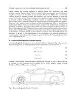
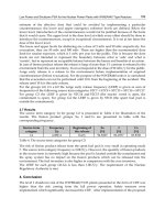
A motor operated valve (MOV) consists of a motor, an actuator, and a valve. Fig. 1 shows a
schematic diagram of an MOV. A motor that is bolted to the actuator housing drives the
actuator. Attached to the motor shaft is the pinion gear, which drives a gear train. The gear
train drives a worm that is splined onto the opposite end of the worm shaft. This worm
assembly is capable of moving axially as it revolves with the worm shaft. The axial
movement is a means of controlling the output torque of the actuator. The worm drives a
worm gear that rotates the drive assembly. As the drive sleeve rotates, the stem nut raises or
lowers a valve stem. When the valve is seated or obstructed, then the worm gear can no
longer rotate, and the worm slides axially along its splined shaft compressing a spring pack.
This axial movement operates a torque switch, causing the motor to be de-energized.
Fig. 1. Schematic diagram of MOV
Nuclear Power – Operation, Safety and Environment
112
An MOV with such operational principles is an essential element to control the piping flow
in nuclear power plant or other facilities. In fact, the operational failure of a safety-related
MOV in a nuclear power plant can have catastrophic results. Therefore, it is necessary that
the operability of the safety-related MOVs should be integral and required in the design
basis conditions. The US Nuclear Regulatory Commission (NRC) issued Generic Letter (GL)
89-10 regarding safety-related MOV testing and surveillance (USNRC, 1989). Subsequently,
in South Korea, the Korea Institute of Nuclear Safety (KINS) required similar testing and
verification, as follows:
Reviewing and documenting the design basis for the operation of each MOV
Establishing the correct switch settings
Demonstrating the MOV to be operable at the design basis differential pressure and/or
flow
Once the operability of each MOV was proven, the need arose to preserve the operability of
every tested MOV to maintain the safety of nuclear power plants. The USNRC and KINS
issued regulatory requirements, which specify periodic verification (PV) of the operability of
MOVs. The requirements recommend utilities to develop an effective PV program of MOV
design capability, considering the fact that aging can decrease the thrust/torque output of
motor actuators (USNRC, 1996). To address the two types of requirements described above,
at least in part, Korean nuclear power plants have implemented static diagnostic tests that
can provide information on the thrust/torque output of the motor actuator, and any
changes to the motor-actuator output as a result of aging effects. The first static test for each
MOV had been conducted from 1999 to 2004, in order to guarantee its operability and
design basis conditions. The second static test has been conducted from 2005, ongoing to the
present, in order to implement PV requirements. Up until 2009, it had been assumed that the
actuator efficiency, one of the most important factors in evaluating the motor actuator
output, does not degrade over time. In other words, the design efficiency provided by
manufacture had been used in the calculation of motor actuator output. In addition, in the
event that the design efficiency had not been provided by the manufacturer, the design
efficiency of other manufacture with similar motor speed and actuator size had been used.
Therefore, the purpose of this chapter is to confirm the validation of the design efficiency by
analyzing the efficiency behavior over time for motor operated gate and globe valves with
rising stem, and comparing the design efficiency with the efficiency calculated from a
method that is introduced in this chapter.
It is presented herein that most actuators of gate and globe valves have minor variations in
efficiency from test-to-test, but no increasing or decreasing trend over time, as well as
demonstrating higher efficiency than the design efficiency. The efficiency variations for
some actuators with lower motor speed, lower actuator size, and lower gear ratio also were
not increased or decreased over time, but their design efficiency was susceptible to decrease
below the their original value. For those actuators, the threshold efficiency was calculated
for the purpose of replacing their design efficiency.
From 2010, those results with two other evaluation studies over time on stem/stem nut
friction coefficient and valve disk/seat friction coefficient have been applied for the PV
program of safety-related MOVs in Korean nuclear power plants. The three studies
including the contents introduced in this chapter have helped us to develop optimized PV
program that can enhance the operability of the valves. Furthermore, they have made key
roles in extending the maximum test frequency from 5 years to 10 years.
A Study on the Actuator Efficiency Behavior of
Safety-Related Motor Operated Gate and Globe Valves
113
2. Calculation of actuator efficiency
2.1 Data acquisition
As described in Section 1, the diagnostic static tests have been conducted to ensure the
motor actuator output of safety-related MOVs for 20 units of nuclear power plants from
1999 to the present in Korea. For each valve, more than two tests have been conducted. The
first test was the design basis test from 1999 to 2004, and the second was the periodic test
from 2005 to 2009. Each test was composed of one ‘as-found’ and two ‘as-left’ tests to
compare and analyze conditions before and after maintenance jobs, according to the field
test procedures. The comprehensive static test data for each valve were used in this study.
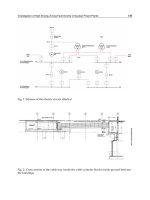
In the tests, the actuator torque and the three phases of currents and voltages were
measured from the strain gage type sensor attached on the stem, and current and voltage
probes installed at the power lines toward the actuator, respectively. Fig. 2 shows the
sensors installed to measure currents and voltages at the valve. The measured values for
gate and globe valves were used in analyzing their respective actuator efficiency behavior.
Fig. 2. A picture of installed sensors at a valve test
2.2 Efficiency calculation process
The actuator efficiency is a factor transferring motor torque produced by an electric motor
into actuator torque, necessary in rotating actuator inner gears. The typical efficiency can be
calculated using the following expression:
OVRMTq
Tq
(1)
Where
is the actuator efficiency,
][ lbftTq
is the actuator torque,
][ lbftMTq
is the
motor torque, and, OVR is the overall gear ratio provided by the manufacturer. In this
study, the equation (1) was used to calculate the efficiency.
2.2.1 Data preparation
As shown in equation (1), the values of actuator torque and motor torque can be used to
calculate the efficiency. The measured actuator torque in the static tests was applied directly
for the equation (1). The motor torque was not measured directly in the static tests.
Accordingly, in order to calculate actuator efficiency, a method to estimate motor torque
Nuclear Power – Operation, Safety and Environment
114
was introduced. In this chapter, the motor torque was estimated by a motor torque
estimator, NEET (S.C. Kang et al., 2006), which can estimate the motor torque using the
three phases of currents and voltages, and resistance values between phases measured in
the static tests. The NEET was developed on the basis of several assumptions. First, the
stator windings are assumed to be sinusoidally wound to couple only to the fundamental-
space-harmonic component of air-gap flux. Second, the self-inductances of the rotor are
assumed not to vary with rotor angular position. Finally, linear magnetics are assumed.
Under these assumptions, the air-gap torque produced by a two-phase induction motor,
which can be transformed from the three-phase induction motor is given by
()
ss ss
TP i i
(2)
Where,
s
and
s
are the flux linkages of the two stator phases.
s
i
and
s
i
are the
currents of the two stator phases and
P is the number of pole pairs. The currents
s
i
and
s
i
can be directly measured at the stator terminals. The flux linkages can also be
determined from terminal measurements. For a two-phase machine,
sss
S
sss
i
d
R
i
dt
(3)
Where,
s
and
s
are the two stator voltages and
s
R is the stator phase resistance. Thus,
the motor torque is expressed only in terms of stator variables, which can be measured in
field test. Except for the NEET, other motor torque estimators can be used in the estimation
of motor torque. Fig. 3 shows an example of motor torque signal estimated by NEET using
the electrical data acquired from a field test.
Fig. 3. An example of motor torque signal estimated by NEET
A Study on the Actuator Efficiency Behavior of
Safety-Related Motor Operated Gate and Globe Valves
115
2.2.2 Efficiency calculation
By substituting the estimated motor torque, the measured actuator torque, and the overall
gear ratio provided by manufacturer into the equation (1) the efficiency can be calculated
easily.
Fig. 4. An example of efficiency calculation area
In this study, the added algorithm into the NEET for the calculation of efficiency was used,
and the efficiency calculation procedures from the algorithm are as follows:
a. Read the estimated motor torque signal.
b. Read the measured actuator torque signal.
c. Input the overall gear ratio.
d. Establish the area to be analyzed from the two signals above (Fig. 4): the left and right
reference points of the area were set up based on the starting point of seating in the
actuator torque signal, and the point in the motor torque signal where power is turned
off, respectively.
e. Calculate the actuator efficiency of each point within the established area, including the
reference points by using the equation (1) (Fig. 5).
f. Calculate the average actuator efficiency by dividing the total sum of efficiency of each
point by the total number of points in the area. As a matter of convenience, the average
actuator efficiency is referred to as the actuator efficiency henceforth.
g. Calculate the two 'as-left' actuator efficiencies of the design basis test, and 'as-found'
efficiency of the periodic test for each valve by applying the procedures from (a) to (f).
h. Calculate the average value of the two 'as-left' actuator efficiency (avg. 'as-left'
efficiency), the difference between avg. 'as-left' efficiency and the 'as-found' efficiency
(efficiency), and the time interval between design basis test and periodic test needed
to analyze the efficiency behavior over time.
Fig. 5. An example of calculated actuator efficiency for each point
Starting point of
seating in actuator
torque signal
Point that power
is off in the motor
tor
q
ue
Calculation area
Nuclear Power – Operation, Safety and Environment
116
2.3 Efficiency behavior analysis process
As the known equation (1), actuator efficiency is dependent on motor torque, actuator
torque, and the overall gear ratio. One of the important parameters in determining the
motor torque output is motor speed. In addition, one of the important parameters in
determining the actuator torque output is maximum motor torque rating. Accordingly, the
motor speed, maximum motor torque rating, and overall gear ratio were selected as major
factors in analyzing the efficiency behavior for gate and globe valves. The design
information about these factors included in this study is described in Table 1.
The efficiency behavior by the three factors described above was analyzed according to the
following process:
a. Analyze the distribution of the avg. 'as-left' and 'as-found' efficiencies based on the test-
to-test time interval in order to address the potential degradations with the passage of
time. The time interval covers the efficiency variations over a period of several years.
b. Compare the avg. 'as-left' and 'as-found' efficiency with the design efficiency. In this
study, the pullout efficiency, which is the lowest efficiency among the staring, stall and
pullout efficiencies usually provided by manufacturers, was selected as the design
efficiency because most nuclear power plants use the efficiency in the calculation of the
actuator output torque.
c. Modify the design efficiency based on the analysis results of item (b), if necessary.
Motor
Manufacturer
Motor
Speed
(RPM)
Actuator
Manufacturer
Actuator
Model
Overall
Gear Ratio
Max.
Torque
Rating
Design
Efficiency
Reliance 1800 Limitorque
SMB-000 33.5~62.5 120 0.4
SMB-00 23~81.1 260 0.4
SMB-0 34.9~54.8 700 0.4
SMB-1
50.4~60.1
1100
0.4
103.2 0.35
SMB-2 26.4~67.4 1950 0.4
SMB-3
53.7~70.9
4200
0.4
98.6 0.38
3600
AMB-000 36.5 120 0.4
SMB-00
34.1~41
260
0.45
67.5 0.4
SMB-0 31.3~39.1 700 0.45
SMB-1 27.2~35.9 1100 0.45
SMB-2 46.6~82.5 1950 0.4
SMB-3 66.1~70.9 4200 0.4
Table 1. Design information of tested valves
A Study on the Actuator Efficiency Behavior of
Safety-Related Motor Operated Gate and Globe Valves
117
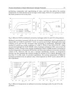
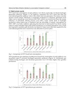
3. Efficiency behavior
Fig. 6 to 8 depict the actuator efficiency distribution for the avg. 'as-left' efficiency ( blue),
'as-found' efficiency (□ red), and efficiency ( green) by motor speed, maximum motor
torque rating, and overall gear ratio, respectively. In the figures, the x-axis is the time
interval between the design basis test and the periodic test. The y-axis includes the actuator
efficiency and efficiency (-0.2 to +0.2). The figures also include the design efficiency
provided by manufacturer. Based on the results displayed in the figures, the efficiency
behaviors over time were analyzed.
3.1 Motor speed
The efficiency distribution of the actuators with design efficiency, 0.4 was shown in Fig. 6 by
the motor speed 1800 RPM (Fig. 6a) and 3600 RPM (Fig. 6b). In both figures, efficiency
was distributed in the positive and negative areas evenly over time. The actuator efficiencies
have variations in efficiency from test-to-test, but no increasing or decreasing trend over
time. However, from the distribution of the avg. 'as-left' efficiency and 'as-found' efficiency,
most of the actuators with 3600 RPM are observed to possess greater efficiency than the
design efficiency, 0.4, while some actuators with 1800 RPM have lower efficiency than the
design efficiency. From those observations, we concluded that motor speed does not affect
the age-related or service-related degradation, while the efficiency of actuators with 1800
RPM can be susceptible to a decrease below the design efficiency.
3.2 Overall gear ratio
In order to analyze if the OVR affects the potential degradation in efficiency, the various
OVRs were grouped by 20~40, 40~60, and 60~80 (Fig. 7a, 7b, 7c). The design efficiency of the
groups is 0.4. In the three figures, efficiency was distributed in the positive and negative
areas evenly over time. The actuator efficiencies have variations in efficiency from test-to-
test, but no increasing or decreasing trend over time.
However, the greater number of actuators was distributed in the area below design
efficiency as the OVR increased. From those observations, we concluded that OVR does not
affect the age-related or service-related degradation, while the efficiency of actuators with
more OVR can be susceptible to a decrease below the design efficiency.
3.3 Maximum motor torque rating
The efficiency distribution of the various actuators was shown in Fig. 8 by the maximum
motor torque rating (Fig. 8a to Fig. 8n). In the figures, efficiency was distributed in the
positive and negative areas evenly over time. The actuator efficiencies have variations in
efficiency from test-to-test, but no increasing or decreasing trend over time.
Some valve’s efficiencies of 120 and 260 of maximum motor torque rating with an 1800 RPM
motor (Fig. 8a, 8b) were showing up in the region below the design efficiency line. However,
such trends appeared in the other actuators only with the 1800 RPM motor. The design
efficiencies for those actuators were considered still available because data points showing
such behavior are less than two at most for an actuator, and the deterioration from the
design efficiency is small and can be explained based on the following engineering
judgments. First, one avg. 'as-left' efficiency of 700 of maximum motor torque rating is lower
than the design efficiency (Fig. 8c) but the behavior was considered temporary because the
Nuclear Power – Operation, Safety and Environment
118
'as-found' efficiency was recovered up to the design efficiency. The same behavior was also
observed for 1950 of maximum motor torque rating (Fig. 8e). In the Fig. 8e, both avg. 'as-left'
and 'as-found' efficiency were lower than the design efficiency, but the maximum deviation
from the design efficiency was less than 11% approximately, which is an approximation of
the sum of 8% for uncertainty of sensors for stem torque and 3% uncertainty of motor torque
estimator based on NEET.
From these observations, maximum motor torque rating does not affect the efficiency
degradation over time, but lower motor torque rating could have lower efficiency than the
design only, for 120 and 260 of maximum motor torque rating with the 1800 RPM motor.
(a) 1800 RPM
(b) 3600 RPM
Fig. 6. Efficiency distribution by motor speed
A Study on the Actuator Efficiency Behavior of
Safety-Related Motor Operated Gate and Globe Valves
119
(a) OVR 20~40
(b) OVR 40~60
(c) OVR 60~80
Fig. 7. Efficiency distribution by OVR
Nuclear Power – Operation, Safety and Environment
120
(a) 120 of max. motor torque rating (1800 RPM)
(b) 260 of max. motor torque rating (1800 RPM)
(c) 700 of max. motor torque rating (1800 RPM)
A Study on the Actuator Efficiency Behavior of
Safety-Related Motor Operated Gate and Globe Valves
121
(d) 1100 of max. motor torque rating (1800 RPM)
(e) 1950 of max. motor torque rating (1800 RPM)
(f) 4200 of max. motor torque rating (1800 RPM, 53.7~70.9 OVR)
Nuclear Power – Operation, Safety and Environment
122
(g) 4200 of max. motor torque rating (1800 RPM, 98.6 OVR)
(h) 120 of max. motor torque rating (3600 RPM)
(i) 260 of max. motor torque rating (3600 RPM, 34.1~41 OVR)
A Study on the Actuator Efficiency Behavior of
Safety-Related Motor Operated Gate and Globe Valves
123
(j) 260 of max. motor torque rating (3600 RPM, 67.5 OVR)
(k) 700 of max. motor torque rating (3600 RPM)
(l) 1100 of max. motor torque rating (3600 RPM)
Nuclear Power – Operation, Safety and Environment
124
(m) 1950 of max. motor torque rating (3600 RPM)
(n) 4200 of max. motor torque rating (3600 RPM)
Fig. 8. Efficiency distribution by max. motor torque rating
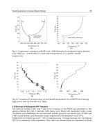
4. Threshold value calculation
As described in Section 3, the actuator efficiency of gate and globe valves have variations in
efficiency from test-to-test, but no increasing or decreasing trend over time. Some of the
variation is due to, for example, uncertainty in test measurements or in the estimation of
motor torque. Some of the variation can be due to random variation in efficiency. Although
the efficiencies of the two actuators,120 and 260 of motor torque rating with an 1800 RPM
motor, also were not increased or decreased over time, where their values are susceptible to
be lower than design values. The decrease can be due to the various combinations of causes
such as lower motor speed, lower maximum motor torque rating, overall gear ratio,
operational environment, maintenance history after installation of those valves. For those
actuators, change of design efficiency is needed to verify proper MOV setup and to quantify
operational margin, as well as to provide any needed information on potential actuator
degradation. Therefore, the threshold efficiencies for the two actuators are established using
a deterministic approach (JOG, 1994), based on engineering judgment, which bounds 95% of
A Study on the Actuator Efficiency Behavior of
Safety-Related Motor Operated Gate and Globe Valves
125
the efficiency data. This is shown by the dashed lines in Fig. 9 and Fig. 10 of the labeled
threshold boundary. The intersection of a +45 line and a horizontal line at efficiency = 0
creates a wedge-shaped boundary. For points on the +45 line, design efficiency + efficiency
= 0 constant. In other words, all data points on such a line will end up at the same final
efficiency after a change in efficiency occurs. Points to the right of the line will end up at a
higher efficiency and points to the left of the line will end up at a lower efficiency. The
efficiency = 0 line is also used as a discriminator because points with negative efficiency
(below the line) are not a concern regarding potential decrease in efficiency. This threshold
boundary can be positioned until a place is found where 5% of the data lie to the left of the +45
line and above the efficiency = 0 line (i.e., within the 135 wedge). In this position, the
intercept of the +45 line with the x-axis is the threshold efficiency. For 95% of the data,
efficiency decreases will not result in a final efficiency exceeding the threshold. Using this
approach, a threshold value that bounds 95% (1 out of the 25 data points in Fig. 9 and 1 out of
the 26 data points in Fig. 10) of the data for maximum torque rating 120 and 260 with 1800
RPM motor is determined as 0.332 and 0335, respectively.
Fig. 9. Threshold efficiency for motor torque rating, 120 with 1800 RPM
Fig. 10. Threshold efficiency for motor torque rating, 260 with 1800 RPM
Nuclear Power – Operation, Safety and Environment
126
5. Conclusion
The actuator efficiency has variations in efficiency from test-to-test, but no increasing or
decreasing trend over time. In other words, there is no potential degradation in efficiency
due only to the passage of time. Under certain conditions, however, decreases in efficiency
to below the design efficiency were observed. Specifically, the actuators with low speed, low
actuator size, and high gear ratio are susceptible to decrease in efficiency. However, these
decreases tend to occur progressively down to a plateau level because those actuators have
variations in efficiency from test-to-test, but no increasing or decreasing trend over time.
In this chapter, the two actuators that have 120 and 160 of motor torque rating with an 1800
RPM motor appeared to possess those behaviors. For the two actuators, change of design
efficiency is needed to verify proper MOV setup and to quantify operational margin, as well
as to provide any needed information on potential actuator degradation. Accordingly, the
threshold efficiencies for the 120 and 160 of motor torque rating which bounds 95% of the
efficiency data were determined as 0.332 and 0.335, respectively. The threshold values and
efficiency behaviors over time can be applied only for the actuators described in the Table 1,
because the design efficiencies and features of actuators depend on manufacturers.
However, when it is assumed that design efficiencies are pertinent for some actuators, it can
be possible to evaluate the potential degradation in design efficiencies only for the actuators
with lower speed motor, lower actuator size, and higher gear ratios based on the results of
this chapter.
6. Acknowledgment
The authors express their sincere appreciation to KHNP (Korea Hydro & Nuclear Power
Company) for its support in the behavior analysis of the actuator efficiency.
7. References
USNRC, Generic Letter 89-10 (1989). Safety Related Motor Operated Valve Testing and
Surveillance, USA
USNRC, Generic Letter 96-05 (1996). Periodic Verification of Design-Basis Capability of
Safety-Related Motor-Operated Valves, USA
S.C. Kang, S.K. Park, D.H. Lee, Y.S. Kim (2006). Motor Control Center (MCC) Based
Technology Study for Safety-Related Motor Operated Valves, Nuclear Engineering
and Technology, Vol. 38, No. 2, 155-162.
JOG, (2004). Joint Owners’ Group (JOG) Motor Operated Valve Periodic Verification
Program Summary, pp. E1-E2, USA.
7
Investigation of High Energy Arcing Fault
Events in Nuclear Power Plants
Heinz Peter Berg
1
and Marina Röwekamp
2
1
Bundesamt für Strahlenschutz
2
Gesellschaft für Anlagen - und Reaktorsicherheit (GRS) mbH
Germany
1. Introduction
Operating experience from different industries has shown a considerable number of
reportable events with non-chemical explosions and rapid fires resulting from high
energy arcing faults (HEAF) in high voltage equipment such as circuit breakers and
switchgears.
High energy arcing faults can occur in an electrical system or component through an arc
path to ground or lower voltage, if sufficiently high voltage is present at a conductor with
the capacity to release a high amount of energy in an extremely short time. High energy
arcing faults may lead to the sudden release of electrical energy through the air.
The significant energy released in the arcing fault of a high voltage component rapidly
vaporizes the metal conductors involved and can destroy the equipment involved. The
intense radiant heat produced by the arc can cause significant damage or even destructions
of equipment and can injure people. However, this problem has been underestimated in the
past (Owen, 2011a and 2011b).
Arcing events are not limited to the nuclear industry. Examples for such events could be
found, among others, in chemical plants, waste incineration plants, and in conventional as
well as in nuclear power plants underlining that high-energetic arcing faults are one of the
main root causes of fires in rooms with electrical equipment (HDI-Gerling, 2009).
An evaluation of several loss incidents in different types of industrial plants has shown that
causes for the generation of arcing faults are mainly due to (HDI-Gerling, 2009):
contact faults at the screw-type or clamp connections of contactors, switches and other
components due to, e.g., material fatigue, metal flow at pressure points, faulty or soiled
clamp connections,
Creeping current due to humidity, dust, oil, coalification (creeping distances, arcing
spots),
Mechanical damage due to shocks, vibration stress and rodent attack,
Insulation faults due to ageing (brittleness), introduction of foreign matter and external
influences.
Investigations of HEAF events have also indicated failures of fire barriers and their elements
as well as of fire protection features due to pressure build-up in electric cabinets,
transformers and/or compartments, which could lead to physical explosions and fire. These
events often occur during routine maintenance.
Nuclear Power – Operation, Safety and Environment
128
HEAF have been noted to occur from poor physical connections between the equipment and
the bus bars, environmental conditions and failure of the internal insulation (Brown et al.,
2009).
The interest in fire events initiated by high energy arcing faults has grown in nuclear
industry due to more recent events having occurred at several nuclear installations.
In the ongoing discussion on an international level it appeared necessary to find a common
understanding about the definition of high energy arcing faults.
Currently, high energy arcing faults are seen as high energy, energetic or explosive electrical
equipment faults resulting in a rapid release of electrical energy in the form of heat,
vaporized metal (e.g. copper), and pressure increase due to high current arcs created
between energized electrical conductors or between an energized electrical conductor and
neutral or ground.
Components that may be affected include specific high-energy electrical devices, such as
switchgears, load centres, bus bars/ducts, transformers, cables, etc., operating mainly on
voltage levels of more than 380 V (OECD/NEA, 2009a).
The energetic fault scenario consists of two distinct phases, each with its own damage
characteristics and detection/suppression response and effectiveness:
1. First phase: Short, rapid release of electrical energy which may result in projectiles
(from damaged electrical components or housing) and/or fire(s) involving the electrical
device itself, as well as any external exposed combustibles, such as overhead exposed
cable trays or nearby panels, that may be ignited during the energetic phase.
2. Second phase, i.e., the ensuing fire(s): this fire is treated similar to other postulated fires
within the zone of influence.
However, a common definition of high energy arcing faults is expected as one result of a
comprehensive international activity of the OECD on high energy arcing faults in the
member states of the Nuclear Energy Agency (NEA) (see below).
A variety of fire protection features may be affected in case of high energy arcing faults
events by the rapid pressure increase and/or pressure waves (e.g. fire barriers such as walls
and ceilings and their active elements, e.g. fire doors, fire dampers, penetration seals, etc.).
The safety significance of such events with high energy arcing faults is non-negligible.
Furthermore, these events may have the potential of event sequences strongly affecting the
core damage frequency calculated in the frame of a probabilistic fire risk assessment.
2. High energy arcing faults and work safety
Although only the technical consequences for nuclear power plants and other nuclear
installations in case of a HEAF event are discussed in the following in detail, another
important hazard resulting from arcing faults should not be ignored. This is the possible
injury of workers.
Based on previous statistics it is expected that solely in the U.S. more than 2,000 workers
will be seriously burnt by the explosive energy released during arcing faults within one year
(Lang, 2005). The magnitude of this problem is far reaching, and the following statistics are
staggering (Burkhart, 2009):
44,363 electricity-related injuries occurred between 1992 and 2001,
27,262 nonfatal electrical shock injuries,
17,101 burn injuries,
Investigation of High Energy Arcing Fault Events in Nuclear Power Plants
129
2,000 workers admitted annually to burn centres for extended arc flash injury
treatment.
Three main consequences for workers result from a high energy arcing fault: blinding light,
intense heat and thermo-acoustic effects.
1. Blinding light:
As the arc is first established, an extremely bright flash of light occurs. Although it
diminishes as the arcing continues, the intensity of the light can cause immediate vision
damage and increases the probability for future vision problems.
2. Intense heat:
The electrical current flowing through the ionized air creates tremendously high levels
of heat energy. This heat is transferred to the developing plasma, which rapidly
expands away from the source of supply. Tests have shown that heat densities at typical
working distances can exceed 40 cal/cm². Even at much lower levels, conventional
clothing ignites, causing severe, often fatal, burns. At typical arc fault durations a heat
density of only 1.2 cal/cm² on exposed flash is enough to cause the onset of a second-
degree burn.
3. Thermo-acoustic effects:
As the conductive element that caused the arc is vaporized, the power delivered to the
arc fault rises rapidly. Rapid heating of the arc and surrounding air corresponds to a
rapid rise in surrounding pressure. The resultant shock wave can create impulse very
high sound levels. Forces from the pressure wave can rupture eardrums, collapse lungs
and cause fatal injuries.
Most of these people will neither have been properly warned of the hazards associated with
arc flash nor will they have been adequately trained in how to protect themselves.
While the potential for arc flash does exist for as long as plants have been powered by
electricity several factors have pushed arc flash prevention and protection to the forefront.
The first is a greater understanding of arc flash hazards and the risk they pose to personnel.
Research has started since a few years for quantifying energy and forces unleashed by arc
flash events. This has resulted in the development of standards to better protect workers.
Arc-flash hazard analysis is important in determining the personal protective equipment
required to keep personnel safe when working with energized equipment. Contact with
energized equipment is a commonly known risk; however exposure to incident energy from
an electrical arc is sometimes overlooked. On that background approach boundaries have
been determined to improve the arc flash hazard protection (Lane, 2004)
There is much discussion regarding how thorough an arc-flash hazard assessment must be.
A complete examination of the system would require assessment at each and every possible
work location, a task that is unrealistic to complete. Even if this task was undertaken, some
of the accepted analysis methods pose some concerns as to whether the assessment
considers the ΄most likely΄ fault scenarios.
The fundamentals of arc-flash hazard analysis are discussed in (Avendt, 2008 and Lane,
2004). The methodology used in the arc-flash hazard analysis is recommended in (IEEE,
2002) where techniques for designers and facility operators are provided to determine the
arc flash boundary and arc flash incident energy. How to use this IEEE standard is
described in (Lippert et al., 2005).
First and foremost, when considering arc-flash hazards four primary factors have to be
mentioned which determine the hazard category:
1. System voltage.
Nuclear Power – Operation, Safety and Environment
130
2. Bolted fault current – calculated at the location/equipment to be assessed and
subsequently used to calculate the theoretical arcing fault current.
3. Working distance – as measured from the personnel´s head/torso to the location of the
arc source.
4. Fault clearing time.
Two of the four primary factors determining the arc-flash hazard category have a larger
impact than the others: working distance and fault clearing time.
In (Avendt, 2008) it is underlined that fault clearing time plays the largest role in the arc-
flash hazard category. A time-current curve is frequently used to show the relationship
between current (amps) and response time (seconds). Most protective devices have an
inverse characteristic: as current increase, time decreases. Examples of such curves are given
in (Avendt, 2008).
In order to fulfil the obligation to protect workers, several standards and guidelines are
currently updated or under development.
For example, the Electricity Engineers Association has developed a discussion paper on the
issue of arc flash (EEA, 2010) that will enable the subsequent preparation of a guide which
will provide best practice advice for employers and asset owners needing to determine the
probability of an arc flash occurring, its severity, means of mitigation and relevant personnel
protection equipment.
An overview of various arc flash standards for arc flash protection and arc flash hazard
incident energy calculations are presented in (Prasad, 2010).
3. Systematic query of international and national databases
In order to confirm these indications by feedback from national and world-wide operating
experience, the national German database on reportable events occurring at nuclear power
plants as well as international databases, such as IRS (Incident Reporting System) and INES
(International Nuclear Event Scale), both provided by the International Atomic Energy
Agency (IAEA), or the OECD FIRE Database (cf. OECD/NEA, 2009) have been analysed
with respect to high energy arcing faults events which resulted in a fire and high energy
arcing faults events with only the potential of deteriorating fire safety.
That systematic query underlined that a non-negligible number of reportable events with
electrically induced explosions and extremely fast fire sequences resulting from high energy
arcing faults partly lead to significant consequences to the environment of impacted
components exceeding typical fire effects.
All results of the international and national databases are presented in Tables 1, 2 and 3 in
the same manner, containing in particular the current plant operational state in case of the
event, the information in which component the cause of the event was identified, the voltage
level, if only the impacted component was damaged, and information if fire barriers being
available had been deteriorated.
3.1 International OECD HEAF activity
Due to the high safety significance and importance to nuclear regulators OECD/NEA/CSNI
(Committee on the Safety of Nuclear Installations) has initiated an international activity on
“High Energy Arcing Faults (HEAF)” in 2009 (OECD/NEA, 2009a) to investigate these
phenomena in nuclear power plants in more detail as an important part of better
understanding fire risk at a nuclear power plants which is better accomplished by an
Investigation of High Energy Arcing Fault Events in Nuclear Power Plants
131
international group to pool international knowledge and research means. In this task it is
stated:
“The main objectives of this common international activity are to define in technical terms a
HEAF event which is likely to occur on components such as breakers, transformers, etc., to
share between experts from OECD/NEA member states HEAF events, experiences, research
and potential mitigation strategies. In addition, the physical and chemical phenomena of a
HEAF event shall be investigated and characterized from a fire dynamics perspective. In
this context, a simple model and/or deterministic correlation is intended to be developed to
reasonably and quickly predict the potential damage areas associated with a HEAF.
Furthermore, generally acceptable input criteria and boundary conditions for CFD
(computerized fluid dynamics) models shall be defined being likely to be accepted by
industry and regulatory agencies. In a last step, the needs for possible experiments and
testing to develop input data and boundary conditions for HEAF events to support the
development of HEAF models shall be identified and the correlations and models
developed be validated and verified.”
The working group with members e.g. from Canada, France, Germany, Korea, and the
United States decided during the Kick-Off Meeting at OECD/NEA in Paris in May 2009 that
the goals of the task are to develop deterministic correlations to predict damage and
establish a set of input data and boundary conditions for more detailed modelling which
can be agreed to by the international community.
The output of the OECD activity may directly support development of improved methods
in fire probabilistic risk assessment for nuclear power plant applications. The task may also
result in the definition of experimental needs to be addressed later in a project structure
(OECD/NEA, 2009a).
3.2 Information from of international databases
First information from the international operating experience collected within the IRS
database - for more severe reportable incidents at nuclear power plants - and INES, both
provided by IAEA, is given in Table 1.
In addition, applications of the OECD FIRE Database (cf. OECD/NEA, 2009) have indicated
that a non-negligible contribution of approx. 6 % of the in total 343 fire events collected in
the database up to the end of 2008 (cf. Berg & Forell et al., 2009) are high energy arcing faults
induced fire events. Details can be found in Table 2.
At the time being, the existing data base on high energy arcing faults events in nuclear
installations is still too small for a meaningful statistical evaluation.
However, the first rough analysis of the available international operating experience gives
some indications on the safety significance of this type of events, which potentially will also
result in relevant contributions to the overall core damage frequency.
Up to the end of 2009, thirty-eight high energy arcing faults events have been identified in
the OECD FIRE Database. Details on these events are provided in the following paragraphs.
The database query was started in Germany. One application of the OECD FIRE Database
selected by the German experts was an analysis of events associated with explosions. A
query in this database on the potential combinations of fire and explosion events (cf. Berg &
Forell et al., 2009) indicated a significant number of explosion induced fires. Most of such
event combinations occurred at transformers on-site, but outside of the nuclear power plant
buildings or in compartments with electrical equipment.
Nuclear Power – Operation, Safety and Environment
132
Year of
Occurrence
Reactor
Type
Plant
State
Component
Voltage
Level
Damage
Limited to
Component
Barrier
Deteriorated
Fire /
Explosion
2006 PWR FP
transformer
busbar
20 kV yes no F
2006 BWR FP
switchgear
station
400 kV yes no -
2001 PHWR LP/SD
circuit breaker
cables
not
indicated
no no F
2001 PWR FP power switch
not
indicated
no no E / F
2001 PWR FP circuit breaker
not
indicated
no yes F
2000 PWR FP circuit breaker 6 kV yes yes F
2000 PWR FP circuit breaker 12 kV yes no F
1996 PWR FP power switch
not
indicated
no yes E / F
1996 PWR FP lightning arrester
not
indicated
no no F
1995 PWR FP circuit breaker 6 kV no no E / F
1992 PWR FP switchgear room 6 kV yes no F
1991 PWR FP control cabinet 6 kV yes no F
1991 PWR FP busbar 0.4 kV yes no F
1990 PWR LP/SD
switchgear
station
400 V yes no -
1990 PWR FP busbar 6 kV yes no -
1990 LGR FP busbar 6 kV no no F
1989 PWR FP distribution 6.9 kV no no E / F
1988 PWR FP distribution 13.8 kV yes no E / F
1984 BWR FP main transformer
not
indicated
no yes E / F
1983 GCR LP/SD control panel 5.5 kV no yes E / F
Table 1. Operating experience from HEAF events reported to INES and IRS (from Berg &
Forell et al., 2009)
Investigation of High Energy Arcing Fault Events in Nuclear Power Plants
133
Year of
Occurrence
Reactor
Type
Plant
State
Component
Voltage
Level
Damage
Limited to
Component
Barrier
Deteriorated
Fire /
Explosion
2007 PWR FP
high voltage
transformer
not
indicated
/ 345 kV
yes no E / F
2006 PWR FP
electrically driven
pump
12 kV yes no E / F
2006 PWR FP
high voltage
transformer
6 kV /
20 kV
no yes E / F
2006 PWR LP/SD
medium and low
voltage
transformer - oil
filled
not
indicated
/ 400 kV
no no E / F
2005 BWR FP
high voltage
transformer
not
indicated
yes no E / F
2005 PHWR FP
high voltage
transformer
not
indicated
/ 500 kV
yes no E / F
2003 GCR FP
high voltage
transformer
6.6 kV /
400 kV
no no E / F
2002 BWR LP/SD
high voltage
transformer
not
indicated
yes no E / F
2002 PWR FP
high voltage
breaker
34.5 kV yes no E / F
2001 PWR LP/SD
high or medium
voltage electrical
cabinet
6.6 kV no yes E / F
2001 PWR
not
indicat
ed
high or medium
voltage electrical
cabinet
6.6 kV no no E / F
1999 PWR FP
high voltage
transformer
20 kV /
161 kV
yes no E / F
1995 PWR FP
medium and low
voltage
transformer – dry
not
indicated
/ 130 kV
yes no E / F
1994 PWR FP
high voltage
transformer
not
indicated
/ 400 kV
yes no E / F
1990 PWR FP
high or medium
voltage electrical
cabinet
6.6 kV yes no E / F
1988 PWR LP/SD
high voltage
transformer
20 kV /
400 kV
yes no E / F
1988 PWR FP
high voltage
transformer
20 kV /
400 kV
yes no E / F
1988 PWR FP
high voltage
transformer
20 kV /
400 kV
yes no E / F
Table 2. Operating experience from fire events with HEAF included in the OECD FIRE
Database (from Berg & Forell et al., 2009)