Nuclear Power Operation Safety and Environment Part 7 pot
Bạn đang xem bản rút gọn của tài liệu. Xem và tải ngay bản đầy đủ của tài liệu tại đây (1.99 MB, 30 trang )
Research on Severe Accidents in Nuclear Power Plants
169
Partner Short name Country
VUJE Trnava, a.s. – Inzinierska, Projektova a Vyskumna
Organizacia
VUJE Slovakia
Commission of the European Communities – Joint Research
Centres
JRCs
European
Union
Atomic Energy Canada Limited AECL Canada
Korea Atomic Energy Research Institute KAERI Korea
United States Nuclear Regulatory Commission USNRC USA
Korea Institute of Nuclear Safety KINS Korea
Table 2. List of SARNET2 partners
four years. They represent a large majority of the European actors involved in SA research
plus a few non-European important ones. Diverse types of organizations are represented:
research organizations, universities, industry, utilities, safety authorities and Technical
Safety Organisations (TSO). A new partner, BARC (India), is joining the network in October
2011.
The network is organised with a Steering Committee of ten members in charge of strategy
and decisions, advised by an Advisory Committee of end-user organisations. A General
Assembly, composed of one representative of each SARNET Consortium member, plus the
EC representative, is called periodically for information and consultation on the progress of
the network activities, the work orientations and the decisions taken by the Steering
Committee. A Management Team, composed of the network coordinator and of seven
Work-Packages (WP) leaders, is entrusted with the day-to-day management of the network.
In the continuity of the SARNET FP6 project, the SARNET2 FP7 project has been defined in
order to optimize the use of the available means and to constitute a sustainable consortium
in which common research programmes and a common computer code on SA, ASTEC, are
developed. ASTEC capitalizes the whole knowledge produced in the network through new
or improved physical models. The Joint Programme of Activities can be divided into several
elements:
- Ranking periodically the priorities of the research programmes, harmonizing and re-
orienting existing ones and jointly defining new ones when necessary,
- Performing small and large-scale experiments on the highest priority issues as defined
in the SARNET FP6 project and jointly analysing their results in order to elaborate a
common understanding of the concerned physical phenomena,
- Developing physical models, integrating them into ASTEC, and validating this code
versus experiments and through benchmarks on plant applications with other codes,
- Storing all the experimental results in a scientific database, based on the STRESA tool,
- Disseminating the knowledge to students or young researchers, as well to new nuclear
emergent countries, through educational courses, textbooks, mobility of personnel
between the network partners, and international conferences that become the major SA
event in the world.
On the basis of the outcomes of the SARP work, the research programmes focus on the six
high-priority issues that were presented in Section 4.4. They are analyzed in the WP N°5 to
8. The experimental efforts are mainly devoted to two of these issues for which real progress
toward the closure of the issue is expected: corium/debris coolability and MCCI. For all
these 6 issues, the same method is being adopted: review and selection of available relevant
Nuclear Power – Operation, Safety and Environment
170
experiments, contribution to the definition of test matrices, synthesis of the interpretation of
experimental data, benchmark exercises between codes, review of models, synthesis and
proposals of new or improved models for ASTEC. Indeed a key integration aspect is the set-
up of the technical circles, each covering a specific detailed topic. They bring experimenters
and modellers closer together, concerning test definition, interpretation, model development
etc In each of the domains, additional studies are being performed in order to bring
research results into reactor applications. Calculations of SA scenarios in reactor conditions
are being performed using various computer codes, including ASTEC, in order to evaluate
the importance of the involved phenomena, in particular through uncertainty studies.
Sections 5.2 to 5.6 summarize the work that is performed in the WP5 to 8 and on the ASTEC
code assessment. Section 5.7 summarizes all activities related to dissemination of
knowledge.
5.2 Activities on corium and debris coolability
The major motivation is to reduce or possibly solve the remaining uncertainties on the
possibility of cooling structures and materials during SA, either in the core or the vessel
lower head or in the reactor cavity, in order to limit the progression of the accident. This
could be achieved by water injection, either by ensuring corium retention within the vessel
or at least slowing down corium progression and limiting the flow rates of corium release
into the cavity. These issues are covered within SAM for current reactors, and also within
the scope of the design and safety evaluation of future reactors. The current PSA2 studies
still show very large uncertainties in the results of the core reflooding phase. For the issue of
in-vessel retention in principle two different aspects have to be considered, the probability
for reflooding systems to begin operation in due time, and the status or degree of core
damage. If core damage occurs at high pressure, low pressure reflooding systems cannot
inject against that pressure. But they may be available with a high degree of reliability. In
such conditions it is crucial to evaluate if and when depressurisation of the reactor coolant
system occurs which would lead to immediate reflooding. In the bottom of BWRs
vessel
there is a continuous injection through the control rod and pump seal flushing water.
Depending on the reliability and capacity of these systems and the pressure in the RCS, the
core degradation may be inhibited.
The following three key situations and processes for the investigation of corium and debris
coolability are considered.
Reflooding and coolability of a degraded core
The focus is on
the accident phase after water boil-off in the core. Heating and melting may
produce a severely damaged, partly molten core with relocated material and partly broken
parts. Quenching of such a hot and partly degraded core is the main issue here. The specific
case of reflooding of a debris bed is detailed in Section 6.
The experimental database on degraded core reflooding was analysed to derive the crucial
information about success of reflooding. The QUENCH experiments in KIT constitute the
main part of this database. The behaviour of fuel rod bundles can be outlined in a
“reflooding map” with respect to the reflooding mass flow rate and the core damage state to
deduce the limits up to which final bundle cooling can be expected to be successful and
hydrogen production may be tolerated.
The analyses show that even at the onset of severe core degradation at temperatures up to
app. 2200 K, the accident progression can be stopped with a sufficiently high flowrate for
Research on Severe Accidents in Nuclear Power Plants
171
core reflooding of ~1 g/s per rod. The reflooding map on core degradation and hydrogen
release is still under development and is considered as a tool to summarize the existing
knowledge and to identify blank areas for efficient future experimental work.
Remelting of debris, melt pool formation and coolability
If core cooling fails, a melt pool will form in the core and melt might flow down into
remaining water in the lower head. The TMI-2 accident indicated that even though
coolability of the core is not attained, a coolable configuration may result from break-up of
the melt in the water of the lower head. If cooling in the core and in the lower head is not
possible, the development of a melt pool in the lower head has to be analysed and it has to
be established whether a melt pool can be kept in-vessel due to external vessel cooling; if it
is not possible, the timing and modes of vessel failure have to be considered. This is the
general objective of the LIVE programme (KIT). These phenomena resulting from core
melting are studied experimentally in large-scale 3D geometry and in supporting separate-
effects tests, with emphasis on the transient behaviour. One experimental result is e.g. that
melt pouring near the vessel wall at the beginning of the test results in considerable
asymmetric heat flux distribution even during the steady state. The time period of the
solidification ranges from 50 minutes to several hours, depending on the cooling conditions
and the position of the melt/crust interface.
The external cooling conditions, which are the second important aspect for achieving in-
vessel coolability, are investigated by the CNU experimental programme (CEA) which is a
unique experimental set-up, large scale, dedicated to the study of two-phase flow with
steam production around a heated RPV geometry.
If all the attempts to cool down the vessel fail, the location and size of the vessel breach are
of concern. Up to now the following main conclusions can be drawn for large PWRs: when
the vessel fails, the liquid corium is mainly oxidic with potentially some metal. The mass of
corium that can be ejected into the reactor pit at vessel failure is estimated between 2 and 20
tonnes. The breach is most probably located on the lateral surface of the vessel. Only local
breaches are expected and not vessel unzipping.
Ex-vessel debris formation and coolability
A porous debris bed can be formed in a water pool of the reactor cavity due to the
fragmentation of the molten corium jet ejected from the lower head of the vessel. The water
pool is available through cavity flooding (e.g. SAMs in Swedish and Finnish BWRs) or water
accumulation in the sump of a PWR due to Loss of Coolant conditions or containment
spray. This is a similar process to the in-vessel situation, when melt relocates from the core
to a water filled lower head. The large depth of water pools in BWRs yields additional
effects.
The first issue concerns the debris bed formation by break-up of melt, with the DEFOR
(KTH) and FARO (JRC/IE-Ispra) experiments. The second issue concerns the investigations
on coolability of debris beds, with the STYX (VTT) and DEBRIS (IKE) experiments (for the
latter, see more details in Section 6).
Bringing research results into reactor application
As an example of research results for reactor applications, the IVR via external reactor vessel
cooling (ERVC) has been recognised as a feasible and promising SAM strategy for VVER-
440/V213 reactors. The most important design features of these reactors, favourable for
Nuclear Power – Operation, Safety and Environment
172
adoption of the IVR concept, are low thermal power, RPV without penetrations in lower
head, massive stainless steel vessel internals, large volume of residual water in lower head
and high driving head for natural circulation in ERVC loop.
Recent activities devoted to IVR concept via ERVC for standard VVER-440/V213 reactors
are performed in the frame of SARNET as well as within national programmes performed in
the countries operating this type of reactors. From the results obtained so far it follows that
there should be sufficient gap width (~ 1 cm) between RPV wall and thermal/biological
shield for the coolant flow in natural circulation regime alongside the outer surface of RPV
wall. Further research should be focused on confirmation of the estimated heat flux values.
Here the outcomes of the SARNET2 project and results of ASTEC analysis will be of high
importance.
In order to evaluate the ability of current advanced codes to predict in-vessel core melt
progression and coolability of the degraded core, a benchmark is being organized in close
collaboration with the OECD/NEA/CSNI. It addresses an alternative scenario of the TMI-2
accident.
5.3 Activities on MCCI
In the postulated case of a SA with vessel melt-through, the containment is the ultimate
barrier between the corium and the environment. The addressed situation is the reactor pit
initially dry but with the possibility of water injection later during MCCI. The work
programme has been designed to be complementary with the MCCI project of the
OECD/NEA that finished in 2010.
Recent 2D experiments like VULCANO (CEA) in prototypical materials have provided new
results that questioned the reliability of the available models and their extrapolation to
reactor conditions. As an example, it becomes clear that new effects have to be taken into
account to be able to describe the ablation anisotropy observed in case of silica-rich concrete
and the different behaviour of limestone concrete. This anisotropy was also present in the
ablation of Chernobyl silica-rich concrete. The intention is thus to gain sufficient
experimental data in order to determine which phenomena are responsible for the observed
isotropy/anisotropy of the concrete ablation.
Concerning the oxide/metal configuration, only few experimental programmes were
conducted with stratified pools using simulant melts, for instance in KIT the large-scale 2D
BETA test series with a large test matrix, and the series of COMET experiments, which were
performed in alumina thermite within the LACOMERA EC project. They provided a
valuable database on long-term MCCI for various initial and boundary conditions. The
VULCANO experiments with oxide and metal pools have the unique characteristics of
providing heat to the oxide layer, like in the reactor case. Several experiments were
performed (VULCANO, MCCI-OECD, HECLA in VTT) but more data are required to
improve knowledge in these configurations. The following question remains open: does a
stratified configuration exist in the reality? The other need is to improve in the modelling
the stratification criteria for onset and termination of stratification.
The other current experiments are MOCKA (KIT) at a large-scale
in simulant materials,
COMETA (UJV) for thermochemistry tests on real corium samples, the Laser melting facility
(JRC/ITU), and CLARA and ABI (CEA) SETs in simulant materials.
Water-cooling is the main available way to terminate the concrete ablation. It was mainly
studied within the OECD/NEA MCCI project. Recently, interest has been shown to pursue
R&D on concepts that could be used to provide bottom-cooling in the cavity of current
reactors.
Research on Severe Accidents in Nuclear Power Plants
173
5.4 Activities on containment issues
The considered issue is the threat to the containment integrity, due to two types of highly
energetic phenomena: steam explosion and hydrogen combustion. Steam explosion may be
caused by ex-vessel FCI due to a RPV failure and pouring of the reactor core melt in the
flooded reactor cavity. Hydrogen combustion (deflagration and detonation) may be caused
by ignition of a gas mixture with high local hydrogen concentrations, which may be due to
the imperfect mixing of the containment atmosphere. Phenomena linked to these threats are
considered as well. Essential insights and results from this research should be applicable to
actual NPPs.
Ex-vessel FCI may lead to steam explosion. The corium ejected in the reactor cavity after
vessel failure may lead to high-pressure loads on the containment or vital components in
case of FCI. The work performed in the frame of SARNET and SERENA-1 (OECD/NEA
project) allowed the identification of the major uncertainties that make difficult to quantify
containment safety margins for an ex-vessel steam explosion. These uncertainties mainly
concern the level of void in the pre-mixing phase and the role of material properties on
explosion energetics. A new OECD/NEA project (SERENA-2) has been launched in October
2007 to resolve these uncertainties by performing a limited number of well-designed tests
with advanced instrumentation reflecting a large spectrum of ex-vessel melt compositions
and conditions in the KROTOS (CEA) and TROI (KAERI) facilities, and the required
analytical work to bring the code predictive capabilities to a sufficient level for use in reactor
analyses. The main objective in SARNET is to further review and debate the progress made
in the SERENA-2 programme, and to propose and perform any activity that might be
needed to complement (and possibly have positive feedback on) the work performed in
SERENA-2, with the help of data produced in SARNET such as MISTEE, DEFOR and DROP
experiments in KTH.
Phenomena that are linked to the hydrogen-in-containment issue, which is still today of
highest priority, are addressed. This issue covers the containment thermal-hydraulics,
including the hydrogen distribution, the different hydrogen combustion regimes, their
impact on containment structures and measures to prevent (severe) combustion processes or
at least to mitigate their consequences with specific devices like PARs or with accident
management measures, like containment sprays. The involved experiments are: TOSQAN
and ENACEFF (IRSN
and CNRS/Orléans), MISTRA (CEA), HyKA and DISCO (KIT),
CONAN (Univ. of Pisa), THAI (Becker Technologies, Germany). Benchmarks between codes
are performed on most of these experiments.
5.5 Activities on source term
The overall objective is to reduce the uncertainties associated with calculating the potential
release of radiotoxic fission products to the environment that may occur during a severe
accident in water-cooled nuclear reactors. It concentrates on iodine and ruthenium, given
their high radio-toxicity, noting that the release of ruthenium is enhanced in oxidising
atmospheres, such as those that may follow air ingress into the RCS. The research treats the
transport of these elements through the primary circuit, including consideration of the SG,
and their behaviour in the containment. The prediction of volatile iodine and ruthenium
species in the containment atmosphere of particular importance, because they are hard to
remove by containment sprays or by filtration while venting the containment. For
ruthenium, the enhanced release from the fuel in oxidising conditions is also studied.
Nuclear Power – Operation, Safety and Environment
174
Full advantage is taken of cooperation with international programmes such as Phébus FP
(Clément et al., 2005), the International Source Term Programme (ISTP) (Clément et al.,
2005), and the projects of the OECD/NEA/CSNI, to avoid duplication of experiments, to
help consistency of the programmes and to identify remaining needs.
As concerns the oxidising influence on source term, the technical work concentrates in
particular on ruthenium source term from the fuel up to its behaviour in-containment:
Release of fission products from fuel (FIPRED experiments in INR, RUSET ones in
AEKI, VERCORS past RUSET and VERDON future ones in CEA, Phébus FP past
experiments in IRSN): release from high burn-up and MOX fuels; role of fuel cladding,
i.e. the competition between cladding oxidation, UO
2
oxidation and fission products
release; fission products release under mixed steam-air conditions, which are more
realistic than 100% air conditions in accident situations;
Ruthenium transport in RCS (experiments in Chalmers University): thermodynamic
behaviour of ruthenium oxides; reactivity with surfaces and other chemical compounds
such as caesium;
Ruthenium behaviour in containment (EPICUR experiments in IRSN, VTT ones, THAI
ones in Becker Technologies): behaviour of ruthenium oxides as aerosols, and their
potential conversion to volatile forms; thermodynamic behaviour of ruthenium species
in liquid phase and potential volatilization.
As concerns the iodine chemistry in the RCS and containment, two main situations are
addressed:
Iodine transport in circuits (CHIP experiments in IRSN,
EXSI ones in VTT): kinetics of
gaseous phase reactions; speciation of revaporised iodine and of other fission products;
development of a databank from plant iodine spiking data and associated development
of a correlation-type model covering some steam generator tube rupture (SGTR) events,
volatile iodine mass transfers and adsorption/deposition in SG secondary side in case
of a SGTR event;
Iodine behaviour in containment (EPICUR experiments, RTF ones in AECL):
mechanisms of iodine association with painted surfaces (adsorption of iodine from
particulate iodides deposited on “wetted” surfaces); subsequent volatile iodine
formation from iodine-loaded paint; radiolytic destruction of gaseous iodine species to
form nucleate particles and subsequent behaviour of these particulate iodine oxides;
iodine binding on sump materials and in sump screen blockages; effect of PARs on
iodine source term.
5.6 ASTEC code assessment and improvements
IRSN and GRS jointly develop the ASTEC code to describe the complete evolution of a SA in
a nuclear water-cooled reactor, including the behaviour of engineered safety systems and
procedures used in SAM (Van Dorsselaere et al., 2009). The new series of versions V2
(Figure 3) can simulate the EPR, especially its external core-catcher, and it includes the
advanced core degradation models of the ICARE2 IRSN mechanistic code.
IRSN and GRS deliver the successive code versions and the corresponding documentation
to the code users: ASTEC V2.0 in July 2009; V2.0rev1 in mid-2010 and V2.1 foreseen in 2013.
They also assure the code maintenance and the support to the code users, notably through
Users Club meetings that are organized about every eighteen months (the next one in spring
2012).
Research on Severe Accidents in Nuclear Power Plants
175
Fig. 3. Structure of the ASTEC integral code for SA simulation
Twenty-nine organizations collaborate on the development and assessment of the successive
ASTEC versions. The developments will account for the model improvements proposed by
the joint research activities of the JPA. Besides, four partners work on the model adaptations
to simulate SA sequences in BWR and PHWR
4
reactors: IKE and KTH for BWR, INR and
AECL for PHWR. They write model specifications, and validate the code against adequate
experiments and benchmarking with other codes. Most ASTEC models are already
applicable to these two types of NPPs except for core degradation. The BARC Indian partner
is developing new PHWR core degradation models and validating them against Indian
experiments.
The assessment activity mainly consists:
- On one hand in validating the code against experiments of diverse types (SETs, CETs,
and integral tests). The comparison of code results with integral experiments such as
Phébus FP and with real plant accidents such as TMI-2 is an essential task;
4
PHWR : pressurized heavy water reactors (including the CANDU type that is designed by Canada)
Nuclear Power – Operation, Safety and Environment
176
- On the other hand in covering a broad matrix of ASTEC reactor applications, aiming at
the most important SA scenarios for the diverse types of reactors (PWR including
VVER, BWR and PHWR). Sensitivity and uncertainty calculations are being performed
in order to demonstrate the reliability and consistency of the ASTEC calculations.
Although not the prime objective, partners may benchmark ASTEC with other reference
codes that they master, such as the integral codes MELCOR and MAAP and the
detailed codes such as ICARE/CATHARE, ATHLET-CD, SCDAP/RELAP5, COCOSYS,
CONTAIN, TONUS…
5.7 Spreading of excellence
The objective of the DATANET database, developed in the frame of SARNET, is to collect
the available
SA experimental data in a common format in order to ensure their
preservation, exchange and processing, including all related documentation. The data are
both previous experimental data that SARNET partners are willing to share within the
network and all new data produced within SARNET. DATANET is based on the STRESA
tool (Zeyen, 2009) developed by the Joint Research Centre (JRC) in Ispra (Italy) and now
managed by JRC-IE in Petten (The Netherlands). It consists of a network with several local
databases. All access rights are managed in accordance with the rules adopted in the
SARNET consortium. The protection of confidential data is an important feature that is
taken into account as the information security of the database. Six STRESA nodes are open
and the results of about 250 experiments from 35 facilities have been implemented. JRC-IE
can create new local STRESA nodes for partners and support the users through training
sessions when necessary.
The public web site (www.sar-net.eu) aims at providing general information on the SA
research field to the general public. For the communication between all network members,
the e-collaborative Internet Advanced Communication Tool is used. About 300 papers
related to SARNET work in the last 5 years have been presented in conferences or published
in scientific journals. The dissemination of information is also done through periodic
newsletters or participation to public events.
Four ERMSAR conferences (European Review Meetings on Severe Accident Research) have
been organized in the last five years successively in France, Germany, Bulgaria and Italy as a
forum to the SA community. They are becoming the major event in the world on this topic.
The 4
th
one, hosted by ENEA (Italy) on May 11-12, 2010 in Bologna (Italy), gathered 100
participants.
The Education and Training programme is focusing on raising the competence level of the
university students (Master and PhD) and researchers engaged in SA research. Towards this
purpose, education courses are elaborated on the phenomenology of the SA various areas.
The teaching is not a survey but an in-depth treatment in order to allow the students and
researchers to understand the methodology in the topics further and use analysis computer
codes, mainly ASTEC, more effectively for any type of NPP. The description of the scenarios
with event trees and fault trees is performed, with indication of the probabilities of the
various events occurring. Best-estimate analyses are provided with uncertainty analyses.
Close links exist with the European ENEN association (European Nuclear Education
Network). Four one-week educational courses were organised during the last five years,
gathering from 40 to 100 persons: the latter was organised in the University of Pisa in
January 2011, with a special focus on Gen.III NPPs. Another training course will be
Research on Severe Accidents in Nuclear Power Plants
177
proposed in the future for staff of plant operators or regulatory authorities, with emphasis
on identifying what the SAM procedures are based on, and why they are effective.
The textbook on SA phenomenology was drafted during the SARNET FP6 project. It covers
historical aspects of water-cooled reactors safety principles and phenomena concerning in-
vessel accident progression, early and late containment failure, fission product release and
transport. It contains also a description of analysis tools or codes, of management and
termination of SA, as well as environmental management. It gives elements also on Gen.III
reactors. The final review was performed in 2010, and the publication is planned in the
second part of 2011.
Finally, a programme enables university students and researchers to go into different
laboratories for education and training in the SA area. Some stages for master thesis may be
organised in the ENEN framework to obtain the 20 credits necessary for the achievement of
the European EMSNE (European Master of Science in Nuclear Engineering) certification.
The staff deputation programme has involved for the last five years about 40 secondments
with an average duration of 3 months: a researcher from one laboratory can spend several
months in another European Laboratory where he/she would participate in an area of the
SA research ongoing there.
6. Illustration on a specific R&D issue: Reflooding of debris beds
One of the high-priority issues concerns the core and debris coolability and thermal-
hydraulics within particulate debris during core reflooding. PSA results do not give a
unanimous answer for the ranking of the issue. While in German PSA studies the
possibility of reflooding is classified with low probability, French PSA on 900 MWe
reactors give a higher probability. Finally because reflooding of a degraded core can
potentially terminate the core degradation and stop the accident, corresponding SAM
measures are intended and consequently the investigation of conditions for successful
reflooding is important.
New QUENCH-Debris experiments (KIT) and CODEX experiments (AEKI) are foreseen in
bundle configurations, analysing the relocation of cladding and fuel and the formation and
cooling of in-core debris beds to gain information on the characteristics of the created
particles. The main objective of these tests is the investigation of these processes under
prototypical boundary conditions for a whole bundle. The QUENCH-Debris facility consists
in modifications of the QUENCH existing facility to study debris formation and coolability
within a rod bundle. Two tests are planned during the SARNET2 timeframe.
The DEBRIS facility (IKE) concerns model-oriented experiments for improvement of
constitutive laws for friction and heat transfer as well as study of specific two dimensional
effects under top and bottom flooding conditions at different system pressures. New
POMECO test facilities (KTH) are designed and constructed to perform isothermal and
boiling two-phase flow tests with better instrumentation and flexibility to accommodate
various prototypical conditions: they aim at analyses under boil-off conditions with
emphasis on basic laws and specific 2D effects (downcomers) more oriented at lower head
or ex-vessel situations but also addressing basically the situation in the degraded core.
Both DEBRIS and POMECO programmes deal with irregular particles aiming at realistic
debris.
IRSN is preparing larger quenching experiments with 2D porous media allowing multi-
dimensional progression of the quench front. This PEARL programme (Figure 4) (Stenne et
Nuclear Power – Operation, Safety and Environment
178
al., 2009) will simulate the reflooding of a debris bed, characteristic of an in-core debris bed,
surrounded by a more permeable medium (such as intact structures and rods). PEARL goes
beyond DEBRIS quenching analyses by the larger size (60 cm diameter vs. 15 cm in DEBRIS)
and thus the possibility to perform extended analyses on multidimensional effects. It will
also provide a general basis for the assessment of the overall behaviour described in the
codes (both in- and ex-vessel phenomena).
Fig. 4. PEARL facility (©2010 IRSN)
The PRELUDE preliminary program is ongoing in IRSN to test the performance of the
induction heating system on stainless steel particles, in order to optimize the
instrumentation in a two-phase flow. The debris bed is one-dimensional, with a smaller size
than PEARL, at atmospheric pressure and up to temperatures of 1000°C. The investigated
parameters are:
- Stainless amagnetic steel particles, 2 and 4 mm in diameter,
- Inlet water velocity between 1 and 8 mm/s (4 to 30 m
3
/h/m
2
), in the range foreseen in
PEARL test matrix,
- Power at 300 W/kg (maintained or not during the reflooding phase),
- Initial temperature before reflooding at 420 K, 500 K, 600 K and 1000 K.
Additional PRELUDE experiments were performed to evaluate the power distribution
inside a larger debris bed diameter (from 110 to 280 mm). This campaign ended with two
experiments with a heating sequence of a debris bed (test section diameter 180 mm, particles
4 mm) up to 1000 K at about 140 and 200 W/kg before the water injection. Those
Outlet circuit for steam
Water injection
circuit
Debris bed
with
S.S
Quartz tube
Debris bed with
Quartz and
Pyrex balls
Induction
coil
Electric
connection
Research on Severe Accidents in Nuclear Power Plants
179
experiments were well instrumented with many thermocouples inside the debris bed
(different radial and axial positions) to follow the water front propagation along time
(Figure 5, shows the thermocouples measurements at different axial levels).
0
100
200
300
400
500
600
700
800
2175 2200 2225 2250 2275 2300 2325 2350 2375
10 mm 55 mm
100 mm 155 mm
195 mm
°C
(s)
Fig. 5. PRELUDE measurements of the water front evolution along time
The objective is to assure the consistency between the PEARL, DEBRIS and QUENCH-
DEBRIS experimental programmes.
Concerning the coolability of porous media,
theoretical analyses have indicated the
importance of multi-dimensional effects. Quenching analyses performed in SARNET
showed agreement concerning a strongly favoured coolability by inflow of water from
lateral water-filled regions of the core with higher porosities. Since lateral water inflow,
especially via lower regions, strongly improves coolability, in general the coolability is much
better than concluded from 1D analyses with top flooding. 2D/3D computer codes
including adequate descriptions of constitutive laws are thus required to analyse the real
coolability situation. Also, it is necessary to improve the
modelling of the formation of
porous media in the core.
In parallel, plant applications must be performed, along with uncertainty studies, on
different in-vessel geometrical configurations, taking into account water supply, in order to
reveal major trends (cooling vs. melt pool formation). The modelling work is being done in
the detailed codes ICARE/CATHARE (IRSN) and ATHLET-CD (work by IKE on the
MEWA module of the German GRS code). These codes aim at a detailed understanding and
simulation of the physical phenomena. Their validation on above experiments will allow
improving their models. The final objective is to derive simplified models from these codes
and to implement them into the ASTEC code.
7. Conclusion
For severe accidents in Generation II-III nuclear power plants, R&D is progressing on the
remaining open issues that have been ranked in the SARNET network of excellence. The
Nuclear Power – Operation, Safety and Environment
180
work concerns new experiments and new physical modelling, in particular in the ASTEC
integral code that is considered as the European reference SA code. For Gen.II NPPs, the
objective is to reduce the remaining uncertainties on SA and consolidate the accident
management plans in order to lead their safety level closer to the level of the new Gen.III
plants under construction.
The accident in the Fukushima plant occurred when this chapter was written. It is very
likely that the accident will imply some reorientations of the planned R&D but it is too early
to get a clear view on that aspect. Nevertheless it can be already observed that the highest-
priority issues that were selected in the SARNET work programme have clearly conditioned
the evolution of the accident: for instance reflooding of a degraded core, hydrogen explosion
in the containment, and degradation of fuel bundles and release of fission products in an air
atmosphere (in the case of spent fuel pools). The SARNET work programme is being
reviewed in order to get as soon as possible a feedback of this accident on the needs of
further R&D. In particular, it seems likely that the aspects of mitigation of the SA
consequences will have to be emphasized in the near future.
A first step towards a sustainable integration of the European SA research capacities has
been reached. A strong link must be kept between the “SARNET community” and the
“PSA2 community”, in continuation of the ASAMPSA2 FP7 project on PSA2 best-practice
guidelines (ASAMPSA2, 2011). The European SNETP (Sustainable Nuclear Energy
Technology Platform), that gathers all nuclear fission actors and aims at providing the
stakeholders and the public with a 2020–2050 vision on R&D, has delegated to SARNET the
coordination of R&D on SA for Gen.II-III NPPs. Such a living and unique pool of
experts should periodically assess the remaining issues on SA, notably using the results of
all international programmes (OECD/NEA,
EC FP7-8, ISTP,…), update the research
priorities and propose relevant R&D programmes to address them. Their scope of
investigations could extend in the future to the new Generation IV plant designs.
Efforts will continue in parallel on the transfer of knowledge to younger generations
through the ERMSAR periodic international conferences, educational courses and
delegations in laboratories.
8. Acknowledgements
The authors wish to thank in particular all the authors of the reference (IRSN-CEA, 2007)
and all the members of the SARNET network, as well as the European Commission for its
support to the SARNET network of excellence.
9. References
Albiol, T., Van Dorsselaere, J P., & Reinke, N. (2008). SARNET: a success story. Survey of
major achievements on severe accidents and of knowledge capitalization within the
ASTEC code, Proceedings of EUROSAFE Forum, Paris (France), November 2008.
Available from www.eurosafe-forum.org
Allelein, H J. et al. (2001). Validation Strategy for Severe Accident codes (VASA), FISA 2001:
EU research in reactor safety, Official Publication of European Communities,
Luxembourg
Research on Severe Accidents in Nuclear Power Plants
181
ASAMPSA2 FP7 project. Advanced safety Assessment Methodologies: level 2 Probabilistic
Safety Assessment. Available from www.asampsa2.eu
Birchley, J., Clément, B., Löffler, H., Tromm, W., & Amri, A. (2010). Outcome of the
OECD/SARNET Workshop on In-vessel Coolability. 4
th
European Review Meeting on
Severe Accident Research (ERMSAR-2010), Bologna (Italy), May 2010. Available from
www.sar-net.eu
Clément, B., Zeyen R. (2005). The Phébus FP and International Source Term Programmes.
Proceedings of International Conference on Nuclear Energy for New Europe, Bled
(Slovenia), Sept. 2005
CSNI. (2000). CSNI International Standard Problems, Brief description (1975-1999),
NEA/CSNI/R (2000)5
IRSN-CEA. (January 2007). Research and development with regard to severe accidents in
pressurised water reactors: Summary and outlook. Available from
www.irsn.fr/EN/news/Documents/R_and_D_severe_accident_report.pdf
Magallon, D., et al. (2005). European Expert Network for the Reduction of Uncertainties in
Severe Accident Safety Issues (EURSAFE). Nuclear Engineering and Design, N°235
(2005), pp.309-346
Micaelli, J C., et al. (2005). SARNET: A European Cooperative Effort on LWR
Severe Accident Research. Proceedings of the European Nuclear Conference, Versailles
(France)
NUREG. Phenomena Identification and Ranking Tables (PIRT's) for Loss-of-Coolant
Accidents in Pressurized and Boiling Water Reactors Containing High Burn up
Fuel. NUREG/CR-6744, LA-UR-00-5079
OECD. (2007). Nuclear Safety Research in OECD Countries Support Facilities for Existing
and Advanced Reactors (SFEAR). NEA/CSNI/R (2007)6, ISBN 978-92-64-99005-0
Schwinges, B., et al. (2008). Ranking of Severe Accident Research Priorities. 3
rd
European
Review Meeting on Severe Accident Research (ERMSAR-2008), Nesseber (Bulgaria),
September 2008. Available from www.sar-net.eu
Stenne, N., Fichot, F., Van Dorsselaere, J P., Tromm, W., Steinbrueck, M., Stuckert, J.,
& Buck, M. (2009). R&D on reflooding of degraded cores in SARNET – Focus
on PEARL new IRSN facility. EUROSAFE Forum, Brussels (Belgium), November
2009
Trambauer, K. (2005). Research Needs in the Domain of Severe Accidents. 1
st
European
Review Meeting on Severe Accident Research (ERMSAR-2005), Aix-en-Provence
(France), Nov. 2005. Available from www.sar-net.eu
Van Dorsselaere, J P., Seropian, C., Chatelard, P., Jacq, F., Fleurot, J., Giordano, P., Reinke,
N., Schwinges, B., Allelein, H J., & Luther, W. (2009). The ASTEC integral code for
severe accident simulation. Nuclear Technology, Vol.165, March 2009
Van Dorsselaere, J P., Auvinen, A., Beraha, D., Chatelard, P., Journeau, C., Kljenak, I.,
Sehgal, B.R., Tromm, W., & Zeyen R. (2010). Status of the SARNET network on
severe accidents. International Congress on Advances in Nuclear Power Plants (ICAPP
'10), San Diego, CA (USA), June 2010
Nuclear Power – Operation, Safety and Environment
182
Zeyen, R. (2009). European approach for a perennial storage of Severe Accident Research
experimental data, as resulting from EU projects like SARNET, Phébus FP and
ISTP. ANS winter meeting, Washington (USA), November 2009
9
Imaging of Radiation Accidents
and Radioactive Contamination
Using Scintillators
Tomoya Ogawa et al.
*
Laboratory of Crystal Physics and Technology
Japan
1. Introduction
An accident in a nuclear power plant, which can be caused by an unpredictable event such
as an explosion, fire, and earthquake, has severe and far-reaching consequences. Therefore,
it is crucial to carefully and constantly monitor the plant and precisely detect any radiation
source. Radiation contamination in laboratories and in the environment due to nuclear
fallout is among the issues that require an immediate solution. Radiation detection has
become increasingly important because of the increasing number of nuclear power plants
that have been established to replace conventional power plants, as part of the effort to
suppress carbon dioxide emission. For these purposes, this chapter will discuss the principle
and method of mapping flying radiations. Visual mapping of intensity and direction of
*
Nobuhiko Sarukura
2
, Masahito Watanabe
3
, Tsuguo Fukuda
4
, Nobuhito Nango
5
, Yasunobu Arikawa
2
,
Kohei Yamanoi
2
, Tomoharu Nakazato
2
, Marilou Cadatal-Raduban
2
, Toshihiko Shimizu
2
, Mitsuo Nakai
2
,
Takayoshi Norimatsu
2
, Hiroshi Azechi
2
, Takahiro Murata
6
, Shigeru Fujino
7
, Hideki Yoshida
8
, Kei
Kamada
9
, Yoshiyuki Usuki
9
, Toshihisa Suyama
10
, Akira Yoshikawa
11
, Nakahiro Sato
12
, Hirofumi Kan
12
,
Hiroaki Nishimura
2
, Kunioki Mima
2
, Masahito Hosaka
13
, Masahiro Katoh
14
, Nobuhiro Kosugi
14
, Kentaro
Fukuda
10
, Takayuki Yanagida
11
, Yuui Yokota
11
, Fumio Saito
11
, Kouhei Sakai
2
, Dirk Ehrentraut
11
, Mitsuru
Nagasono
15
, Tadashi Togashi
15
, Atsushi Higashiya
15
, Makina Yabashi
15
, Tetsuya Ishikawa
15
, Haruhiko
Ohashi
15,16
, and Hiroaki Kimura
15,16
2
Institute of Laser Engineering, Osaka University, Japan
3
Department of Physics, Gakushuin University, Japan
4
Fukuda Crystal Laboratory, Japan
5
Ratoc System Engineering Co., Japan
6
Department of Chemistry, School of Science, Tokai University, Japan
7
Department of Materials Process Engineering, Graduate School of Engineering, Kyushu University, Japan
8
Ceramic Research Center of Nagasaki, Japan
9
Furukawa Co., Ltd., Japan
10
Tokuyama Corporation, Japan
11
Institute of Multidisciplinary Research for Advanced Materials, Tohoku University, Japan
12
Central Research Laboratory, Hamamatsu Photonics K.K., Japan
13
Graduate School of Engineering, Nagoya University, Japan
14
UVSOR Facility Institute for Molecular Science, Japan
15
RIKEN XFEL Project Head Office, Japan
16
Japan Synchrotron Radiation Research Institute, Japan
Nuclear Power – Operation, Safety and Environment
184
incident radiations is necessary to detect any radiation accident and/or invisible radiation
contamination. Discussion will focus on directional detection of radiation sources, being the
minimum requirement for identifying and characterizing unpredictable accidents and
contamination.
Specifically, this chapter will discuss two-dimensional imaging of radiation accidents and
radioactive contamination. It will also detail the development of a “panchromatic” detector
that is suitable for use against radiation from different types of sources. This detector
combines several types of scintillating elements into a bundle, which is composed of well-
designed and regularly arranged scintillation fiber-segments or thin cylinders to detect and
display the radiation sources as a map, using the directional sensitivity of the segments or
cylinders for locating sources of incident radiation. In addition, this chapter will discuss the
numerical designs and the characteristics of two detector configurations. These are the
telescope configuration, wherein all the extended lines of the scintillator fiber segments or
thin cylinders composing the bundle are focused to a point; and the magnifier configuration,
wherein all the extended lines of the segments within the bundle are diverging from the
focus.
An integral part of the radiation detector is the scintillator. Scintillators are created and
developed to correctly detect and count incident radiations. In this regard, part of this
chapter will also be devoted to the discussion of the properties of scintillators that are ideal
for use in radiation detectors. In particular, the effect of scintillator shape and decay time
will be outlined, leading to the attributes of an ideal imaging scintillator. For instance, one of
the size effects is the directional sensitivity to incident radiations. This can be realized by
using a thin cylinder-type or a fiber segment-type scintillator. The output signals from the
thin cylinder are proportional to the number of radiations that passed through it, if its
length is good enough to absorb the incident radiations.
To complete the chapter, the performance of various scintillators will be discussed. Among
the scintillators that will be discussed is the praseodymium-doped lithium glass
(APLF80+3Pr), cerium-doped lutetium lithium fluoride (Ce
3+
:LuLiF
4
), zinc oxide (ZnO), and
neodymium-doped lanthanum fluoride (Nd
3+
:LaF
3
).
2. Scintillators
Scintillators are fluorescent materials that mediate the detection of high energy (ionizing)
electromagnetic or charged particle radiation. A scintillator absorbing high-energy radiation
fluoresces at a characteristic Stokes-shifted (longer) wavelength that can be detected by
conventional detectors like photodiodes or photomultiplier tubes. If the properties of the
scintillator are known, then the high-energy radiation that it absorbed can in turn be
characterized. Radiation detectors are typically useful for imaging by utilizing high-
penetration power radiation and for spectroscopy by utilizing characteristic radiation from
each atom. As part of a detection unit, the broad application of scintillators comprises
various scientific disciplines such as high-energy physics, nuclear physics, astronomy, and
mineral exploration. It has also found applications in product quality control, airport
security, nuclear safeguards verification, cargo container inspection, toxic dumpsite
monitor, and environmental monitoring. Moreover, Positron Emission Tomography (PET)
for medical imaging has gained popularity as a common clinical tool for detection of
tumors.
Imaging of Radiation Accidentsand Radioactive Contamination Using Scintillators
185
2.1 Shape of scintillators
Scintillation is caused by collision between a high-energy radiation and an electron
belonging to a heavy dopant atom. This collision is considered as one of the ideal stochastic
processes. As such, a scintillation detector is usually prepared as a very large block to
correctly count incident radiations while excluding its size effects.
Fig. 1. A thin cylinder or fiber segment scintillator and its incident radiation acceptance
angle, where a is its diameter, L is its length, and Φ is the divergence of its sensitivity against
incoming radiation.
One of the size effects is the directional sensitivity to incident radiations. This can be
realized by using a thin cylinder-type or a fiber segment-type scintillator. The output signals
from the thin cylinder are proportional to the number of radiations that passed through it if
its length is good enough to absorb the incident radiations. On the other hand, radiations
crossing obliquely through a segment may or may not generate scintillation even if every
radiation were moving along an identical line. This can, therefore, constitute random noise.
The signals arising from radiation passing directly through the scintillator can be separated
from the random noise generated by radiation crossing the scintillator obliquely through the
well-known noise reduction technique using multi-integration.
In most materials, the refractive index for high energy radiations is nearly equal to unity.
Therefore, the aperture, Φ, of the cylinder for which incident radiations is detected is
2tan
-1
(a/L) (1)
where L and a are the cylinder length and diameter, respectively, as illustrated in Fig. 1.
Surface smoothness of the cylinder is very important since multiple scattering of the
scintillation light at its surface is detrimental to the imaging of output light signals.
2.2 The decay time of scintillation
Since scintillators are created and developed to correctly detect and count incident
radiations, a very short scintillation decay time is desirable for precise time-resolved
radiation measurement. Decay time of well-known scintillators is much less than one
microsecond. For the case of scintillators developed mainly for imaging, measurement is
limited by the refresh rate of the television or monitor. The refresh rate of monitors and
televisions is typically 30 frames per second. It is therefore acceptable that the decay time of
imaging scintillators is in the millisecond range. This decay time is longer than the
requirement for scintillators used in radiation counting. For this purpose, development of
brighter scintillators without regard to decay times would be of primary importance when
developing an imaging device.
Nuclear Power – Operation, Safety and Environment
186
2.3 Scintillation crystals
A comparison of the performance of different scintillator materials is shown in Table 1 (Ishii
& Kobayashi, 1991, 2007). One of the best candidates for imaging will be thin scintillation
cylinders made from CsI:Tl crystals. This material is ideal as an imaging scintillator because
among the materials in Table 1, it has the largest photoluminescence output per radiation
energy of 59,000 photons/MeV. It also has a relatively long decay time of 1 μs. Moreover, it
has a high melting point of 621℃ and is only slightly hygroscopic.
Table 1. Characteristic features of scintillation crystals
3. Configuration and compilation of the scintillation thin cylinders
Visual mapping of intensity and direction of incident radiations is necessary to detect any
radiation accident and/or invisible radiation contamination. For this purpose, thin cylinder
scintillators or fiber segments are compiled to form a bundle where every extended line of
the cylinder is either focused into a point, as shown in Fig. 2 or diverging from a point, as
shown in Fig. 3. The former is referred to as the telescope configuration while the latter is
referred to as the magnifier configuration (Ogawa, 2007, 2010).
3.1 Telescope configuration
Figure 2 demonstrates a typical telescope configuration. The terminal end of the scintillation
cylinder bundle where the focus side is located is optically connected to a two dimensional
photodetector, such as a charge coupled device (CCD). An image intensifier or a micro-
imaging plate is used to amplify the signals before reaching the CCD.
The field angle or aperture of this telescope is determined by R and F, where R is the
diameter of the circle circumscribed by the terminal ends and F is the distance between the
focus and the terminal plane. With this configuration, the intensity and direction of incident
radiations will be indicated as a map on the computer, after image processing.
HE104900.928.2PbWO
4
PET40300001.147.4Lu
2
SiO
5
:Ce
PET60100001.386.71Gd
2
SiO
5
:Ce
X-CT5000150001.067.68CdWO
4
PCT, NP, HE30082001.127.13Bi
4
Ge
3
O
12
6, 3530
*
1.854.51CsI
X-CT1050590001.864.53CsI:Tl
+
2.820002.234.11CsF
General purpose230380002.593.67NaI:Tl
ApplicationDecay
(ns)
PL output
(Photons/MeV)
Radiation length,
X
0
(cm)
Density
(g/cm
3
)
Material
NP: Nuclear physics experiment * Faster decay component
HE: High energy physics experiment + Slight hygroscopicity
Imaging of Radiation Accidentsand Radioactive Contamination Using Scintillators
187
Fig. 2. The telescopic configuration. All the extended lines of the scintillator fiber segments
or thin cylinders composing the bundle are focused to a point.
3.2 Magnifier configuration
For the magnifier configuration, the size of the focal point is nearly equal to or a little larger
than the diameter of the fiber. In this configuration, a radiation source such as an X -ray tube
or a small block of
60
Co is continuously emitting its radiation at the focal point. On the other
hand, the specimen being studied is placed at a plane between the focus and the front of the
bundle. This way, the transparency of this specimen against the radiation will be observed
as its magnified image. This is similar to an optical magnifier. If radiation substances or
radioactive isotopes are scattered on a plane, a map of this contamination will be observed
when the focus of the magnifier either approaches or departs from that plane, as shown in
Fig. 3.
Fig. 3. The magnifier configuration. All the extended lines of the segments within the bundle
are diverging from the focus.
Nuclear Power – Operation, Safety and Environment
188
4. Numerical designs
In this section, we discuss the numerical considerations for designing the telescope and
magnifier configurations. In particular, the characteristic features of the cylinders to be used
in the telescope configuration as well as the diameter of the fiber segments for the magnifier
configuration are discussed.
4.1 Numerical designs of cylinders for the telescope configuration
The sensitivity divergence, Φ, of a thin scintillation cylinder and the aperture for imaging, Θ,
of the cylinder bundle are defined as follows:
Φ = 2 tan
-1
(a/L) (2)
= 2 tan
-1
(R/F) (3)
On the other hand, the total number of the cylinders, N, is given by
N = 3n(n+1) + 1 (4)
where n is number of cylinders along the radius of the circle circumscribed by the terminal
ends. Thus Θ, Φ and n are related as follows:
Φ = (Θ/2n)p (5)
In this equation, p is an overlapping or tolerance factor of the scintillation cylinder or fiber
segment. In our calculations, we chose Θ as 47º, 24º, 8º, and 2.5º because these apertures
correspond to the 50 mm, 100 mm, 300 mm and 1000 mm focal length lens of the 35 mm
camera system, respectively.
The length of a cylinder, L, is such that the incident radiation is enough to be absorbed for
scintillation but the light generated within it will be perfectly received at the terminal end.
In our calculations, L was assumed to be
L = 5Xo (6)
where Xo is the radiation length of the scintillation material. In this case, the incident
radiation will be attenuated to 1/e, which is equal to 0.0067 times (Fukuda et al., 2004). This
attenuation value is acceptable for the present purpose. The radiation length of various
scintillators is summarized in Table 1. As an example, by using a CsI:Tl crystal having an Xo
of 18.6 mm, the suitable crystal length, L, would be 93 mm. Correspondingly, the diameter,
a, of the CsI:Tl cylinders can be obtained using equations (2) and (5) with p = 2. Calculation
results of the diameter of CsI:Tl cylinders for different apertures (Θ) and number of
cylinders (n) are shown in Table 2. It is worth mentioning that the diameter of the
commercially available Bi
4
Ge
3
O
12
(BGO) cylinders is 0.6 times compared to that of CsI:Tl
because the radiation length of BGO is 0.60 times shorter than that of CsI:Tl.
4.2 Numerical designs of fiber segments for the magnifier configuration
The size of the focal point is nearly equal to or a little larger than the diameter of the fiber
segment, as indicated in Fig.3. It is, therefore, more desirable to make thinner fiber
segments. Today, the diameter of commercially available scintillation fibers, for example the
BGO fiber is about 30 μm (Fukuda & Chani, 2007; Fukuda et al., 2004). This is very similar in
size to the focus of a commercial microfocus X-ray tube. If fibers with a 1 μm diameter were
Imaging of Radiation Accidentsand Radioactive Contamination Using Scintillators
189
available, the resolution of the transparent image against radiation will clearly be improved
because the half shadow of the image will be dramatically diminished.
Table 2. The diameter of CsI:Tl scintillation cylinders
5. Scintillators for time-resolved measurement
As mentioned in Section 2.2, a very short scintillation decay time is desirable for precise
time-resolved radiation measurement. Over the past years, several scintillators have been
studied for this purpose, wherein several schemes have been considered in order to improve
the response time of fluoride, oxide, and glass scintillators. In this section, the characteristics
of fluoride, oxide, and glass scintillators will be discussed. Emphasis will be given to the
improvement in the fluorescence decay time. In particular, the scintillation properties of
cerium-doped lutetium lithium fluoride (Ce
3+
:LuLiF
4
), praseodymium-doped lithium glass
(APLF80 + 3Pr), neodymium-doped lanthanum fluoride (Nd
3+
LaF
3
), and zinc oxide (ZnO)
will be discussed.
5.1 Pr-doped glass
In the field of fusion research, understanding the plasma dynamics could very well be the
key in feasibly attaining controlled fusion. Moreover, studying the scattered neutrons is
currently the most viable way of probing the fusion plasma. For this reason, neutron
diagnostics is an indispensable tool for both inertial confinement fusion (ICF) and magnetic
confinement fusion research (Cheon et al., 2008; Glebov et al., 2006; K.A. Tanaka et al., 2004;
Lerche et al., 1995; Petrizzi et al., 2007; Ress et al, 1988). In particular, the observation of
scattered neutrons from the high-density imploded deuterium plasma in laser fusion
experiments is desired (Izumi et al., 2003). At the center of the imploded deuterium fuel
plasma, deuterium-deuterium (DD) neutrons having energy of 2.45 MeV and scattered
neutrons from the fuel deuteron are generated. The scattering probability depends only on
the plasma areal density, which is the radial integral of density ρR, in units of g/cm
2
. In
addition, a wide observable range of up to 3 g/cm
2
is required for future fusion reactors.
These factors make the scattered neutron diagnostics method, highly expected to be further
developed as an invaluable tool in ICF research. For this purpose, a fast-response neutron
scintillator with a high cross section for scattered neutrons is strongly required.
The nuclear reaction,
20 µm41 µm101 µm0.20 mm2.5
o
(f = 1000)
65 µm130 µm325 µm0.65 mm8
o
(f = 300)
195 µm380 µm970 µm1.95 mm24
o
(f = 100)
381 µm763 µm1907 µm3.82 mm47
o
(f = 50)
100
30.301
50
7651
20
1261
10
331
n
N
20 µm41 µm101 µm0.20 mm2.5
o
(f = 1000)
65 µm130 µm325 µm0.65 mm8
o
(f = 300)
195 µm380 µm970 µm1.95 mm24
o
(f = 100)
381 µm763 µm1907 µm3.82 mm47
o
(f = 50)
100
30.301
50
7651
20
1261
10
331
n
N
(The case when p = 2)
The value of f in the parentheses indicates focal length of the lens with the same
aperture under the film size: 35-mm camera system.
Nuclear Power – Operation, Safety and Environment
190
6
Li(n,T)
+ 4.8 MeV (7)
has a large cross section resonant peak, well-fit to the back scattered neutron spectrum peak
around 0.27 MeV, and a large Q value producing enough photons for lower energy scattered
neutrons. Thus, a
6
Li scintillator with a high lithium density is an ideal detector for this
method (Izumi et al., 2003). Since scattered neutrons having energy around 0.27 MeV must
be discriminated from the overwhelming majority of the 2.45 MeV primary neutrons or x-
rays via time-of-flight experiments, a sufficiently fast time response is required. Moreover
we must also discriminate the neutrons scattered by the experimental setup itself such as the
vacuum chamber wall. Thus, the detector has to be placed at close proximity to the fusion
plasma; necessitating a scintillator with a time decay of less than 20 ns. In this work, results
are presented on the fast response time of a custom-developed Pr
3+
(Praseodymium)-doped
lithium glass as a scintillator material (Arikawa et al., 2009).
The Pr
3+
ion with a higher emission cross section in the deep ultraviolet region (~270 nm) is
preferred as a dopant (Yoshikawa et al., 2008) over the slower, albeit more widely-used
Ce
3+
( Cerium) ion with its smaller emission cross section at longer wavelengths (Ehrlich et
al., 1979; Fairley & Spowart, 1978; Suzuki et al., 2002). Additionally, high Li-density fluoro-
lithium glass is chosen as the host material over UV-transparent, Li-doped fluoride crystals
such as LiCaAlF
6
, primarily due to its ease-of-preparation and design flexibility.
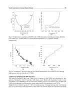
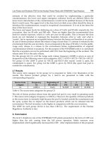
Fig. 4. Photoluminescence (PL) and photoluminescence excitation (PLE) spectrum of the
APLF80+3Pr. The PL peak is observed at 279 nm while the PLE maximum occurs at 234 nm.
The photograph shows the glass scintillator sample. The diameter is 6cm with a thickness of
1 cm.
The APLF80 + 3Pr glass sample, having a composition of 20Al(PO
3
)
3
– 80LiF + 3PrF
3
(in mol)
using 95.5%
6
Li enriched lithium fluoride, is shown in the inset of Fig. 4. It was prepared
using the melt-quenching method, where PrF
3
-containing starting materials were melted in
a glassy carbon crucible at 1100 degrees Celsius under nitrogen atmosphere. The glass melt
was then cooled down to 400 degrees Celsius in the furnace, and subsequently annealed
near the glass transition temperature. The lithium density was measured using an atomic
absorption photometer to be 7.98 w%, 31.6 mmol/cc. This is the highest reported value for
conventional
6
Li glass scintillators, thus far (Saint-Gobain Crystals, 2007-2008). Fluorescence
increase upon 241Am-alpha excitation was observed with higher doping of Pr
+3
. The highest
doping of Pr
+3
was found to be 3% at the present manufacturing procedure. The preliminary
characteristics were reported in (Murata et al., 2009).
Imaging of Radiation Accidentsand Radioactive Contamination Using Scintillators
191
Before the neutron observation experiments were conducted, the spectral- and temporal-
optical characteristics of the sample were evaluated. From the peak of the pulse height
distribution of the APLF80+3Pr sample, we estimated the fluorescence photons yield to be
about 300 photons / 5.5 MeV-alpha, taking into consideration the limited acceptance angle
of the photomultiplier window even though the emission can be regarded to be isotropic in
all directions. Figure 4 shows the photoluminescence (PL) and photoluminescence excitation
(PLE) spectra of the sample. Strong emission at around 278 nm due to the 5d-4f transition,
which was the design wavelength, was seen. Furthermore, the host material was found to
have good transmission in the vacuum ultraviolet region down to 180 nm, and no
absorption at the luminescence region was observed.
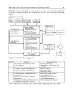
Fig. 5. Streak camera image of the spectral and time resolved luminescence of the APLF+1Pr.
The excitation source is the 4th harmonics of a Ti: Sapphire laser.
The spectrally-resolved fluorescence lifetime of the APLF80+1Pr sample, excited with 217-
nm 150, fs pulses using the 4th harmonics of a Ti:sapphire laser, was measured using a
streak camera as shown in Fig. 5. The spectrally-integrated fluorescence decay profile, along
with the other decay profiles for other excitation sources are shown in Fig. 6; where all the
decay curves were fitted with a single exponential decay in the region from 50 % to 10 % of
the peak value. For ultraviolet excitation, the fluorescence lifetime was determined to be 19.5
± 0.80 ns. The decay from short x-ray excitation pulses from laser-produced plasma was
measured to be 20.8 ± 0.85 ns. In this experiment, a 10-μm thick aluminum plate target was
irradiated by 4 ps/80 J Nd-glass laser pulses. The generated electron energy spectrum of a
few MeV at the peak was also measured using an electron spectrometer. On the other hand,
the fluorescence decay profile for 5.5 MeV
241
Am alpha-particle excitation was 6.7 ± 0.03 ns.
Neutron excitation, having energy from 0.5 MeV to 10 MeV using
252
Cf, exhibited the fastest
decay time of 5.9 ± 0.16 ns. This significant difference of decay times for neutrons and x-ray
excitation is preferable for the time-of-flight measurements, although the mechanism of
response time difference is not clear. A similar difference in the response time was also
observed for conventional Ce
3+
-doped Li glass scintillation (Fairley & Spowart, 1978).
Based on these information, we show the feasibility of the custom-developed APLF80 + 3Pr
scintillator material as a fast-response neutron detector for laser fusion diagnostics. The
detection of ICF-originated neutrons was successfully carried out in laser fusion
experiments at the GEKKO XII facility of the Institute of Laser Engineering, Osaka
Nuclear Power – Operation, Safety and Environment
192
University. In this study, a fusion target made from a deuterated plastic shell was irradiated
by the 12 high-intensity Nd-glass lasers of the GEKKO XII facility. A detailed description of
typical fusion experiment at GEKKO XII is described in (Azechi et al., 1991). As much as
5×10
5
DD-fusion neutrons were observed using conventional neutron detectors, based on
plastic scintillators. The fluorescence from the APLF80 + 3Pr sample that was positioned at
about 10 cm from the fusion target was transmitted using a bundle optical fiber and
detected by an ultraviolet photomultiplier as shown in Fig. 7. Taking into account the
distance between the target and the APLF80+3Pr glass scintillator, and the difference of the
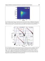
time-of-flight of X-ray (30 cm/ns) and neutrons (2.2 cm/ns), the signal at round 10 ns in Fig.
8 was identified to be that of DD primal neutron. With decay time of about 80 ns, such clear
discrimination between x-rays and neutrons in this short interval is impossible with
traditional cerium doped lithium glass scintillators.
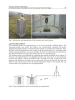
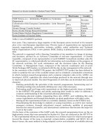
Fig. 6. The APLF+3Pr luminescence lifetime for alpha, neutron, x-ray, and UV pulse
excitation. The lifetime varies from ~20 ns to under 7 ns, depending excitation source. This
variation in the sample’s decay time for different excitation energies suggests its capability
to be used as detector in laser fusion time of flight experiments.
Fig. 7. Experimental set up of the time-of-flight experiment for the neutron detector. The
detector is placed about 10 cm from the deuterated plastic target. The target is irradiated by
12 high energy beams of the GEKKO XII facility of the Institute of Laser Engineering, Osaka
University.
Imaging of Radiation Accidentsand Radioactive Contamination Using Scintillators
193
Fig. 8. The neutron signal at about 12 ns was successfully detected at the GEKKO XII facility
fusion experiment.
5.2 Ce-doped fluoride
As mentioned in section 5.1,
6
Li is known to have a large cross section for high-energy
neutrons. This makes lithium-rich compounds prominent candidates for a host, especially
when doped with a high quantum efficiency light emitting ion. Particularly, Li-rich
fluorides are important hosts for these applications because of their relatively wide
bandgap, which make them transparent even down to the vacuum ultraviolet region (below
200 nm). On the other hand, three trivalent ions are being considered as dopants, namely,
Cerium (Ce
3+
), Praseodymium (Pr
3+
), and Neodymium (Nd
3+
) (van Eijk et al., 1994).
Previously, Nd
3+
:LaF
3
(Nakazato et al., 2010a) and Nd
3+
:La
x
Ba
(1-x)
F
(3-x)
(Cadatal et al., 2007,
2008) have been reported as possible scintillator materials. However, of these three, Ce
3+
has
the smallest energy difference between the 4f and 5d levels, therefore resulting to a more
efficient energy transfer to the dopant ion (van Eijk et al., 1994). The small energy difference
also translates to a longer emission wavelength for Ce
3+
-doped materials. A longer emission
wavelength is advantageous because it can easily match the sensitivity of light sensors. For
these reasons, Ce
3+
:LuLiF
4
(Ce:LLF) is explored as a viable scintillator material (Nakazato et
al., 2010b). This material has been extensively investigated as a tunable ultraviolet laser
medium and amplifier (Dubinskii et al., 1992; Sarukura et al., 1995a, 1995b, 1998).
For the development of scintillators, specifically for nuclear fusion applications, material
optimization and doping concentration are extremely important. Material screening is
typically accomplished through characterization of the material’s response time for different
neutron or photon excitation energies (M. Tanaka et al., 2007). However, since the short-
pulse and high-energy neutron generated by nuclear fusion is not available on a daily basis;
the free electron laser (FEL) can be an alternative excitation source for material screening.
Moreover, the FEL provides flexibility in tunability and operation, therefore making it an
important aide in accelerating material development. Among such FELs, the storage ring
free-electron laser (SRFEL) is an appropriate choice because of its adequately high repetition
rate, which is needed for the suitable evaluation of fluorescence decay times that are
typically in the order of tens of nanonseconds (Hosaka et al., 2002). These decay times have
been characteristically observed from Ce
3+
doped fluorides.
In this section, Ce:LLF is reported as a fast scintillator using a SRFEL operating in the deep
ultraviolet region. The response time is comparable to that of commercially available