Nuclear Power Operation Safety and Environment Part 2 potx
Bạn đang xem bản rút gọn của tài liệu. Xem và tải ngay bản đầy đủ của tài liệu tại đây (1.05 MB, 30 trang )
World Experience in Nuclear Steam Reheat
19
(a)
(b)
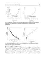
Fig. 9. Temperature variations at BNPP Unit 1 SHS channels at transitional regime (Smolin
et al. 1965): (a) – coolant inlet (T
in
) and outlet temperatures (T
out
) and (b) –sheath
temperature.
(a)
(b)
Fig. 10. Variations of pressure drop (a) and sheath temperature (b) at BNPP Unit 2 during
high-power start-up (Smolin et al. 1965).
3.8 Start-up of Beloyarsk NPP reactors
The start-up testing of the Unit 1 and Unit 2 reactors of the BNPP are described in this
section. During the Unit 1 start-up, both loops were filled with deaerated water, water
circulation was established, air was removed, and the pressure was raised up to 10 MPa and
3 MPa in the primary and secondary loops, respectively (Aleshchenkov et al. 1971).
Equipment was heated up at 10 – 14% of reactor power. Average heat-up rate was kept at
30C/h as measured at the separators. This value was chosen based on experience of drum
Nuclear Power – Operation, Safety and Environment
20
boilers operation, though reactor equipment allowed significantly higher heat-up rate. No
heat removal was provided during the heat-up to the 160C coolant temperature at the
reactor outlet. The water level was formed at 160C in the bubbler and the excess heat
started being released to the turbine condenser. When water temperature at the outlet of the
SHS channels reached 230C the heat-up was terminated. Total heat-up time was about 9 h.
At the next step, water was purged from SHS channels. The transient processes took place in
the second loop while constant pressure and boiling-free cooling of BWs were provided in
the primary loop. Reactor power was rapidly reduced to ~2% of its nominal level and
feedwater flow rate was reduced to provide water level in the SGs to purge SHS channels.
Water-steam mixture from evaporators and steam from the steam loop were directed to the
bubbler and then to the deaerator and the turbine condenser.
The purging of SHS channels started after the level in the SGs had been formed. The
purging regime was monitored by the pressure drop between the reactor inlet and outlet
steam headers and the coolant temperature at the outlet of each SHS channel. Additional
steam discharge by increased pressure drop rate was achieved and thus the purging was
accelerated by opening gate valves in front of the bubbler for 1 – 2 min. The pressure drop
rate was chosen based upon the allowed temperature condition and was set to ~0.15
MPa/min. Overall time for the level formation in the evaporators was ~8 – 10 min, the time
of purging ~6 – 10 min. The gate valves in front of bubblers were closed and reactor power
was increased after the purging had finished. Thus, the pressure and the temperature in
SHS channels were increase. After 2 hours the SHS channels purging had been finished and
the reactor achieved a stable operation at 10% power level. The heating of steam pipes and
the turbine was initiated and the turbine connection to the power line was prepared. Further
power increase was made once the turbine had been connected to the power line.
The first loop was transferred to the boiling flow regime and the separators levels were
formed at 35% reactor power and ~6 MPa pressure. During the transient to the boiling
regime, the operating conditions of the MCPs were continuously monitored. Water
temperature was maintained 5 − 6C below the boiling margin for intake pipes of the main
circulation pumps. Level formation in the separators was accompanied by smooth pressure
change. It took about 3 h for the water to reach controlled level in the separators, the time
being dependent only on the separator bleed lines throughput.
The specific features of a single-circuit flow diagram made the sequence of the BNPP Unit 2
start-up operations somewhat different. SHS channels purging and transition to boiling
regime in the BW channels took place simultaneously. Filling of the circuits and equipment
heat-up were the same as in Unit 1. The terminal heat-up parameters were higher (P 9.3
MPa and T 290°C). Two main circulation pumps were used to drive coolant circulation in
the evaporating loop. After heat-up the reactor power was reduced to 2 – 3% of nominal
level. SHS channels purging, and transition to boiling regime in the BW channels took place
after the heat-up. The feedwater flow rate was considerably reduced, water was purged out
of the separators, and the flow rate to the bubblers was increased to form levels in the
separators. As a result, the water in the fuel channels and separators boiled causing the
purging of water and water-steam mixture from SHS channels. The monitoring of the
purging process was the same as at the Unit 1. After SHS channels purging had been
completed, the reactor power was increased and steam flow into the bubbler was reduced at
the reheated steam temperature rise rate of about 1°C/min with the pressure drop between
the steam headers at least ~50 – 60 kPa. The automatic level control system was put into
operation as soon as the water in the separators reached the rated level. The subsequent
World Experience in Nuclear Steam Reheat
21
reactor power increase, turbine preparation, and connection of the turbine to the power line
were the same as for Unit 1 (Aleshchenkov et al. 1971).
3.9 Pumps
All pumps at the BNPP were high-speed type (3000 rpm). Serial high-power feeding pumps
were used. Other pumps were special canned type, in which the motor spindle and pump
spindle were revolved in a pumped medium and were separated from the motor stator by a
thin hermetic nichrome plate. Bearing pairs of the pumps were lubricated and cooled by
pumped water. The revolving details of bearings were made of advanced hard alloys and
bearing bushes were made of special plastics. Some minor failures were observed in
operation of MCP (Emelyanov et al. 1972). Those were due to cracks in nichrome jacket, to
malfunctioning of fan of the stator front parts, to pilot-valve distribution system
imperfections, and to failures of the fasteners in the pump interior. Modernizations of some
individual elements of the MCP and reconstruction of independent pump cooling loops
improved optimal on-stream time between maintenance and repairing (16,000 h). As a
result, the failure probability of the MCP was reduced to minimum. Operating experience of
the MCP showed that serial pumps could be used instead of specially designed canned
pumps under no fragment activity in the loops conditions that were achieved at BNPP.
3.10 Water chemistry
The experiments on effectiveness of water and steam radiolysis suppression by hydrogen in
BW and SHS channels respectively were performed after 16 months of Unit 1 operation.
Water and steam samples were taken at the drum-separator, MCPs, inlet and outlet of SHS
channels. Ammonia dosing was terminated before the test for determination of the required
amount of hydrogen that was necessary to suppress water and steam radiolysis that was
partially caused by ammonia decomposition (Yurmanov et al. 2009b). Hydrogen
concentration in saturated steam at the separator was found to be 45 – 88 nml/kg and in
circulation water at the main circulation pump was found to be 2.75 – 12.8 nml/kg. Despite
some hydrogen excess, oxygen concentration decreased from 2.28 mg/dm
3
to 0.1 mg/dm
3
.
Dissolved oxygen concentration in the circulating water at the main circulation pump did
not exceed 0.01 – 0.03 mg/dm
3
. At the next stage of experiments, steam radiolysis in SHS
channels and the possibility of suppressing it by hydrogen concentration levels were
studied. Hydrogen concentration was set to 1.2 – 6.2 nml/kg in steam and 1.2 – 1.8 nml/kg
in circulating water. Oxygen concentration was below 0.15 mg/kg in steam and about 0.02
mg/dm
3
in the circulating water. The obtained results demonstrated effective suppression
of water radiolysis.
Additional research was carried out at 60% reactor power. The results showed that the
oxygen concentration was decreased to 0.03 mg/kg at the SHS channels outlet only at 45
nml/kg hydrogen concentration. The water-steam mixture at the turbine ejector consisted of
hydrogen (62 – 65%) and oxygen (8 – 10%) at a hydrogen concentration of 40 – 45 nml/kg.
The water-steam mixture was needed to be diluted with air to a non-explosive state, i.e.,
hydrogen volume fraction was to be decreased below 2 – 3% (Shitzman 1983).
The equipment for Unit 2 was made from the following constructional materials: stainless
steel (5500 m
2
, 900 m
2
of which were used for the core); carbon steel (5600 m
2
); brass and
cupronickel (14,000 m
2
); stellite (4.8 m
2
). The studies showed that radiolytic gases
production rate was approximately 5 times lower than that of a BWR of the same power.
Nuclear Power – Operation, Safety and Environment
22
Water radiolysis at the BW channels of the BNPP Unit 1 was suppressed by ammonia
dosing. This kept radiolityc oxygen content in water at several hundredths of a milligram
per liter. Ammonia dosing wasn't used at Unit 2 due to the danger of corrosion of the
condenser tubes and low-pressure heaters. Radiolytic fixation of oxygen in the steam that
was bled to high-pressure heaters was achieved by hydrazine hydrate dosing. The operation
norms and the actual quality of coolant at the BNPP Unit 2 are listed in the Table 7.
Additional information on water flow regime may be found in paper by Konovalova et al.
(1971).
All the indicators of coolant quality were in the range set by the water regime regulations
during normal operating period.
Parameters
Feed
water
Reactor
circulating
water
Reactor
bleed
water
Saturated / Reheated
steam
Turbine
condensate
SiO
2-
3,
μg/kg
– – 100–300 5–15 / 5–15 –
Chlorides, μg/kg 25 25 25 – / – –
Iron oxides, μg/kg 20–60 20–60 30–60 20–30 / 20 –30 0
Copper, μg/kg – – 7–30 0.4 / – 0.8
Specific activity, Ci/l – – 10
–5
– / 10
–7
–
Oxygen, μg/kg 10–15 30 30 (5–6)·10
3
/ (5–6)·10
3
40–50
Ammonia, mg/kg 1–25 0.6–1.4 0.6–1.4 0.8–2 / 0.8–2 1–2
pH 9.2–9.5 8–9 9–9.5 9–9.5 / 9–9.5 9–9.5
Table 7. Actual parameters of BNPP Unit 2 coolant quality during period of normal
operation (Konovalova et al. 1971).
In August 1972 (after 4.5 years of operation) neutral no-correction water was implemented
at Unit 2 (Dollezhal et al. 1974). Operation in the new conditions revealed the following
advantages over the ammonia treated state:
1. The cease of feedwater ammonia treatment led to the zero nitrate content in the reactor
circulation water. This allowed an increase of the pH from 4.8 to the neutral level at the
300°C operating temperature.
2. Balance of the corrosion products content in the circulation water and chemical flushing
of the BW channels showed that the rate of metallic oxide deposits formation on the
fuel-bundles surfaces in the evaporating zone of the reactor was three times lower using
no-correction water.
3. The Co-60 deposition rate outside the core was 7 – 10 times lower using no-correction
water.
4. Condensate purification experience using no-correction water allowed an increasing
filter service cycle by 6 times.
3.11 Section-unit reactor with steam-reheat
The BNPP became the first in the world industrial NPP with a uranium-graphite power
reactor. Examination of the main characteristics of the BNPP reactors (for example, see Table
3) shows that that performance of such type of reactors could be improved. BNPP used
slightly enriched uranium and the calculations showed that increasing enrichment to 5%
would increase fuel burn-up 4 − 10 times (up to 40,000 MWdays/t).
World Experience in Nuclear Steam Reheat
23
All channel reactors were constructed with traditional cylindrical shape of core. Therefore,
power increase in such a reactor could be attained by increasing the number of working
channels in the core and a proportional increase in diameter size. However, increase in
power per reactor would then be limited by the maximum size of the reactor upper plate
that could be built and withstand a high load. A way out of this situation was found in
section-unit design of the channel reactor with a rectangular core. Such a shape would allow
separating not only the core, but also reactor as a whole, into equal geometry sections. Then
the reactor of a specified capacity can be constructed of the required number of sections.
Each section would stay the same for reactors of different power outputs, and, consequently,
core width and maximum size of the upper metalwork would stay the same too. Therefore,
the power of a section-unit reactor power would not be limited by the size of the upper plate
(Emelyanov et al. 1982).
Section-unit type reactors with coolant at supercritical fluid conditions (see Figure 11) was
developed at Research and Development Institute of Power Engineering (RDIPE, Moscow,
Russia) as an improvement to the existing RBMK (Russian acronym for Channel Reactor of
High-Power).
Fig. 11. Schematic of RDIPE SCW NPP (Aleshchenkov et al. 1971): 1 – reactor; 4 – preheating
channel; 5 – first SHS; 6 – second SHS; 11 – Condensate Extraction Pump (CEP); 14 –
deaerator; 15 – turbo-generator; 17 – condenser; 18 – condenser purifier; 19 – mixer; 20 –
start-up separator; 21 – intermediate steam reheater; 22 – low-pressure regenerative
preheater; 23 – high-pressure regenerative preheater; 24 – feed turbo-pump; and 25 –
booster pump.
Rod fuel bundles were inserted into Zirconium SHS (SHS-Z) channels (see Figure 12) on the
core level. UO
2
fuel elements with steel sheath were designed. Fuel bundles were covered by
a sheath to hold SHS-Z channel wall below 360C (Grigoryants et al. 1979). Therefore,
saturated steam entering the channel was split into two streams. About 25% of the steam
flowed through the annular gap cooling the SHS-Z channel wall. Both streams mixed at the
core exit. Steam mixture was at about 455C. Tests with SHS-Z channels were performed in
BNPP Unit 1 to check design decisions. SHS-Z channels were tested in 23 – 24 start-ups –
shutdowns, including 11 emergency shutdowns of the reactor when the steam temperature
change rate was 20 – 40C/min during the first 3 minutes of an automatic control system
operation, and 5C/min after that. SHS-Z channel wall temperature reached 400 – 700C
and that of the fuel bundles sheath reached 650 – 740C during start-up operation at a steam
Nuclear Power – Operation, Safety and Environment
24
pressure of 2.45 – 4.9 MPa. Channels were operated about 140 h at high temperature
conditions. Studies showed that fuel element seal failures were mainly due to short-duration
overheating (Mikhan et al. 1988).
1 – suspension rod;
2 – thermal screen;
3,4 – outer and inner tubes of bearing body;
5 – inner tube reducer;
6 – upper reducer of outer tube;
7 – fuel bundle;
8 – graphite sleeves;
9 – thermal screen and inner tube seal;
10 – lower reducer of outer tube; and
11 – reactor.
Fig. 12. Principal scheme of SHS-Z (Mikhan et al. 1988)
Additional information on SHS-Z-channel tests in BNPP Unit 1 may be found in the papers
by Grigoryants et al. (1979) and by Mikhan et al. (1988).
4. Conclusions
The operating experience of the reactors with nuclear steam reheat worldwide provides vital
information on physical and engineering challenges associated with implementation of
steam reheat in conceptual SuperCritical Water-cooled Reactors (SCWRs). Major
advancements in implementation of steam reheat inside the reactor core were made in the
USA and Russia in 1960s – 1970s. Three experimental reactors were designed and tested in
the 1960s – 1970s in the USA. In the former Soviet Union, nuclear steam reheat was
implemented at two units at the Beloyarsk NPP. Operating experience of the units showed a
World Experience in Nuclear Steam Reheat
25
possibility of reliable and safe industrial application of nuclear steam reheat right up to
outlet temperatures of 510 − 540°C after over a decade of operation. Thermal efficiency of
the Beloyarsk NPP units was increased by 5% as the result of implementing nuclear steam
reheat. The introduction of nuclear steam reheat was economically justified in cases where
the steam was superheated up to 500°C and higher with the use of stainless-steel-sheath fuel
elements.
The experiments and operating experience obtained to date also indicate that further
improvements in SHS channel design and in reactor design are possible.
5. Acknowledgements
Financial supports from the NSERC/NRCan/AECL Generation IV Energy Technologies
Program and NSERC Discovery Grant are gratefully acknowledged.
The authors would like to acknowledge contributions of Wargha Peiman, Amjad Farah and
Krysten King.
6. Nomenclature
K
eff
effective multiplication constant
K
ir
neutron flux irregularity coefficient
P pressure, MPa
R radius, m
T temperature, °C
x steam quality
Greek letters
power split between superheated-steam and boiling-water and channels
Subscripts
el electrical
in inlet
out outlet
th thermal
Abbreviations and Acronyms
AECL Atomic Energy of Canada Limited
BNPP Beloyarsk Nuclear Power Plant
BONUS BOiling NUclear Superheater
BORAX BOiling Reactor Experiment
BW Boling-Water (channel)
BWR Boiling Water Reactor
CEP Condenser-Extraction Pump
ESADE Superheat Advance Demonstration Experiment
FWP FeedWater Pump
MCP Main Circulation Pump
NSERC Natural Sciences and Engineering Research Council (Canada)
NPP Nuclear Power Plant
Nuclear Power – Operation, Safety and Environment
26
NRCan Natural Resources of Canada
RBMK Russian Acronym for Channel Reactor of High-Power
RDIPE Research and Development Institute of Power Engineering (Moscow, Russia)
SADE Superheat Advance Demonstration Experiment
SCW Supercritical Water
SCWR SuperCritical Water-cooled Reactor
SG Steam Generator
SHS SuperHeated Steam (channel)
SS Stainless Steel
USAEC United States Atomic Energy Commission
Z Zirconium
7. References
Aleshchenkov, P.I., Zvereva, G.A., Kireev, G.A., Knyazeva, G.D., Kononov, V.I., Lunina, L.I.,
Mityaev, Yu.I., Nevskii, V.P., and Polyakov, V.K., 1971. Start-up and Operation of
Channel-Type Uranium-Graphite Reactor with Tubular Fuel Elements and Nuclear
Steam Reheating, Atomic Energy (Атомная Энергия, стр. 137–144), 30 (2), pp. 163–
170.
Aleshchenkov, P.I., Mityaev, Yu.I., Knyazeva, G.D., Lunina, L.I., Zhirnov, A.D., and
Shuvalov, V.M., 1964. The Kurchatov’s Beloyarsk Nuclear Power Plant, (In
Russian) Atomic Energy, 16 (6), pp. 489–496.
Dollezhal, N.A., Malyshev, V.M., Shirokov, S.V., Emel’yanov, I.Ya., Saraev, Yu.P.,
Aleshchenkov, P.I., Mityaev, Yu.I., and Snitko, E.I., 1974. Some Results of
Operation of the I.V. Kurchatov Nuclear Power Station at Belyi Yar, Atomic Energy
(Атомная Энергия, cтр. 432–438), 36 (6), pp. 556–564.
Dollezhal, N.A., Aleshchenkov, P.I., Bulankov, Yu.V., and Knyazeva, G.D., 1971.
Construction of Uranium-Graphite Channel-Type Reactors with Tubular Fuel
Elements and Nuclear-Reheated Steam, Atomic Energy (Атомная Энергия, стp.
149–155), 30 (2), pp. 177–182.
Dollezhal, I.Ya., Aleshchenkov, P.I., Evdokimov, Yu.V., Emel’yanov, I.Ya., Ivanov, B.G.,
Kochetkov, L.A., Minashin, M.E., Mityaev, Yu.I., Nevskiy, V.P., Shasharin, G.A.,
Sharapov, V.N., and Orlov, K.K., 1969. BNPP Operating Experience, (In Russian),
Atomic Energy, 27 (5), pp. 379–386.
Dollezhal, N.A., Emel'yanov, I.Ya., Aleshchenkov, P.I., Zhirnov, A.D., Zvereva, G.A.,
Morgunov, N.G., Mityaev, Yu.I., Knyazeva, G.D., Kryukov, K.A., Smolin, V.N.,
Lunina, L.I., Kononov, V.I., and Petrov, V.A., 1964. Development of Power Reactors
of BNPP-Type with Nuclear Steam Reheat, (In Russian), Atomic Energy, (11), pp.
335–344 (Report No. 309, 3
rd
International Conference on Peaceful Uses of Nuclear
Energy, Geneva, 1964).
Dollezhal, N.A., Krasin, A.K., Aleshchenkov, P.I., Galanin, A.N., Grigoryants, A.N.,
Emel’anov, I.Ya., Kugushev, N.M., Minashin, M.E., Mityaev, Yu.I., Florinsky, B.V.,
and Sharapov, B.N., 1958. Uranium-Graphite Reactor with Reheated High Pressure
Steam, Proceedings of the 2
nd
International Conference on the Peaceful Uses of
Atomic Energy, United Nations, Vol. 8, Session G-7, P/2139, pp. 398–414.
World Experience in Nuclear Steam Reheat
27
Emelyanov, I.Ya. , Mikhan, V.I., Solonin, V.I., Demeshev, R.S., Rekshnya, N.F., 1982. Nuclear
Reactor Design, (In Russian). Energoizdat Publishing House, Moscow, Russia, 400
pages.
Emelyanov, I.Ya., Shasharin, G.A., Kyreev, G.A., Klemin, A.I., Polyakov, E.F., Strigulin,
M.M., Shiverskiy, E.A., 1972. Assessment of the Pumps Reliability of the Beloyarsk
NPP from Operation Data, (In Russian). Atomic Energy, 33 (3), pp. 729–733.
Grigoryants, A.N., Baturov, B.B., Malyshev, V.M., Shirokov, S.V., and Mikhan, V.I., 1979.
Tests on Zirconium SRCh in the First Unit at the Kurchatov Beloyarsk Nuclear
Power Station, Atomic Energy (Атомная Энергия, стр. 55–56), 46 (1), pp. 58–60.
Konovalova, O.T., Kosheleva, T.I., Gerasimov, V.V., Zhuravlev, L.S., and Shchapov, G.A.,
1971. Water-Chemical Mode at the NPP with Channel Reactor and Nuclear Steam
Reheat, (In Russian), Atomic Energy, 30 (2), pp. 155–158.
Mikhan, V.I., Glazkov, O.M., Zvereva, G.A., Mihaylov, V.I., Stobetskaya, G.N., Mityaev,
Yu.I., Yarmolenko, O.A., Kozhevnikov, Yu.N., Evdokimov, Yu.V., Sheynkman,
A.G., Zakharov, V.G., Postnikov, V.N., Gladkov, N.G., and Saraev, O.M., 1988.
Reactor Testing of Zirconium Steam-Reheat Channels with Rod Fuel Elements in
Reactors of the First Stage of BNPP, (In Russian), BNPP Operating Experience:
Information Materials (in 4 volumes), USSR Academy of Sciences, Ural Branch, 207
pages.
Novick, M., Rice, R.E., Graham, C.B., Imhoff, D.H., and West, J.M., 1965. Developments in
Nuclear Reheat, Proceedings of the 3
rd
International Conference, Geneva, Vol. 6,
pp. 225–233.
Petrosyants, A.M., 1969. Power Reactors for Nuclear Power Plants (from the First in the
World to the 2-GW Electrical Power NPP) , (In Russian). Atomic Energy, 27 (4), pp.
263–274.
Pioro, I., Saltanov, Eu., Naidin, M., King, K., Farah, A., Peiman, W., Mokry, S., Grande, L.,
Thind, H., Samuel, J. and Harvel, G., 2010. Steam-Reheat Option in SCWRs and
Experimental BWRs, Report for NSERC/NRCan/AECL Generation IV Energy
Technologies Program (NNAPJ) entitled “Alternative Fuel-Channel Design for
SCWR” with Atomic Energy of Canada Ltd., Version 1, UOIT, Oshawa, ON,
Canada, March, 128 pages.
Ross, W.B., 1961. Pathfinder Atomic Power Plant, Superheater Temperature Evaluation
Routine, An IBM-704 Computer Program. United States Atomic Energy
Commission, Office of Technical Information, Oak Ridge, TN, 49 pages.
Samoilov, A.G., Pozdnyakova, A.V., and Volkov, V.S., 1976. Steam-Reheating Fuel Elements
of the Reactors in the I.V. Kurchatov Beloyarsk Nuclear Power Station, Atomic
Energy (Атомная Энергия, стр. 371-377), 40 (5), pp. 451–457.
Shitzman, M.E., 1983. Neutral-Oxygen Water Regime at Supercritical-Pressure Power Units, (in
Russian), Energoatomizdat Publishing House, Moscow, Russia.
Smolin, V.N., Polyakov, V.K., Esikov, V.I., and Shuyinov, Yu.N., 1965. Test Stand Study of
the Start-up Modes of the Kurchatov’s Beloyarsk Nuclear Power Plant, (In
Russian). Atomic Energy, 19 (3), pp. 261–269.
USAEC Report ACNP-5910, 1959. Allis-Chalmers Manufacturing Co., Pathfinder Atomic
Power Plant, Final Safeguards Report, May.
USAEC Report (MaANL-6302), 1961. Design and Hazards Summary Report—Boiling
Reactor Experiment V (Borax-V), Argonne National Laboratory.
Nuclear Power – Operation, Safety and Environment
28
USAEC Report PRWRA-GNEC 5, 1962. General Nuclear Engineering Corp., BONUS, Final
Hazards Summary Report, February.
Vikulov, V.K., Mityaev, Yu.I., Shuvalov, V.M. , 1971. Some Issues on Beloyarsk NPP Reactor
Physics, (In Russian), Atomic Energy, 30 (2), pp. 132–137.
Yurmanov, V.A., Belous, V. N., Vasina, V. N., and Yurmanov, E.V., 2009a. Chemistry and
Corrosion Issues in Supercritical Water Reactors, Proceedings of the IAEA
International Conference on Opportunities and Challenges for Water Cooled
Reactors in the 21
st
Century, Vienna, Austria, October 26−30.
Yurmanov, V.A., Vasina, V. N., Yurmanov, E.V and Belous, V. N., 2009b. Water Regime
Features and Corrosion Protection Issues in NPP with Reactors at Supercritical
Parameters", (In Russian), Proceedings of the IAEA International Conference on
Opportunities and Challenges for Water Cooled Reactors in the 21
st
Century,
Vienna, Austria, October 26−30.
2
Integrated Approach for Actual Safety Analysis
Francesco D’Auria, Walter Giannotti and Marco Cherubini
GRNSPG - University of Pisa
Italy
1. Introduction
Actual trend in reactor safety deterministic analysis are evolving toward best estimate
approach. Best estimate analyses imply use of best estimate codes and input data. The best
estimate concept is not limited to thermal-hydraulics rather in general terms it covers many
fields, likewise three dimensional neutron kinetics, structural analysis and containment
performance evaluation.
The general frame is to put efforts in avoiding conservative assumptions performing
analysis adopting the best tool available for each specific topic, all contributing to give an
integrated evaluation of the plant response.
The needs to adopt an integrated approach in performing safety analysis come from the
inherent complexity of a Nuclear Power Plant and from the tight interactions among the
subsystems constituting the plant itself. These interactions directly involve the necessity to
consider a broad spectrum of disciplines typically coming into play in different not
interacting analyses.
An example of the integral approach is given in the present document. The integral
approach has been pursued for the safety analyses of the ‘post-Chernobyl modernized’
Reactor Bolshoy Moshchnosty Kipyashiy (RBMK) specifically for Smolensk 3. These
analyses were performed at the University of Pisa within the framework of a European
Commission sponsored activity.
The mentioned analyses deal with events occurring in the primary circuit, as well as
excluding those events originated from plant status different from the nominal operating
conditions. Following the evaluation of the current state of the art in the safety analysis area,
targets for the analysis were established together with suitable chains of computational
tools. The availability of computational tools, including codes, nodalisations and boundary
and initial conditions for the Smolensk 3 Nuclear Power Plant, brought to their application
to the prediction of the selected transient evolutions that, however, are not classified as
licensing studies.
The integrated approach for safety analysis yields to the evaluation of complex scenarios not
predictable adopting just a single computational tool. Example is given considering the
Multiple Pressure Tube Rupture (MPTR) event which constitute one of the main concern of
this kind of plant.
The content of this document includes an introduction to the critical issues to be accounted
for in the frame of an integral safety analysis approach; the selection of suitable
computational tools to proper deal with the scenario subject of the investigation; an
Nuclear Power – Operation, Safety and Environment
30
approach on how to link (coupling issues) the selected tools; the use of intermediate code
outcomes and interpretation of the global predicted plant behaviour. All the aspects
presented in general terms are applied in the case study of a Multiple Pressure Tube
Rupture having as reference plant the Smolensk 3 Nuclear Power Plant. The selected event
may occur as a consequence of a fuel channel blockage which (if not detected) brought to the
rupture of the affected pressure tube. The dynamic loads generated by its breach may lead
to the rupture of the surrounding pressure tubes. Direct consequence of the pressure tube
rupture is the pressurization of the reactor cavity which envelopes all the core. In the case of
Multiple Pressure Tube Rupture event, involving a large number of pressure tubes, the
lifting of the reactor cavity top may occur, putting in direct connection the core with the
environment. The present example is a kind of analysis that cannot be performed if an
integrated approach is not adopted.
2. Framework
The best estimate approach is the actual trend of the NPP deterministic analysis
(International Atomic Energy Agency [IAEA], 2008). The concept of best estimate is
generally applied to the software codes used in the analysis. However the best estimate
approach concept has a broader meaning. It applies to the general framework of the
analysis, and it involves not only the codes, but the kind of analyses to be performed, the
approach to realize the models to be realized for the analyses, the input data including
boundary and initial conditions also. The best estimate approach is not only connected with
a calculation performed with a best estimate code. The result of the analysis is a best
estimate evaluation, if all the aspects of the analysis (input data, systems models, results) are
best estimate, in addition to the codes. As a consequence the use of a best estimate code,
assuming not best estimate data or systems model cannot be considered a best estimate
analysis.
A calculation of a complex system like a NPP, poses a lot of issues to perform a best estimate
analysis. The main relevant aspect is constituted by the many areas involved in the analysis
of a NPP. Knowledge in many technical areas are necessary. The solution can be obtained by
“linking” in a single instrument of investigation the different tools developed for
investigation in each of the different areas.
2.1 Complexity of the approach
The scope is the safety of nuclear power plants, is demonstration of the capability to keep
the radiation exposure of personal and population within specified limits. It is ensured by
maintaining the integrity of safety barriers, which are part of the plant defence in depth
concept.
A series of barriers prevents the release of radioactive fission products from their source
beyond the reactor containment and into the environment. In analyzing the NPP safety, it is
essential to assess the integrity of these barriers and to decide to what degree the response of
the whole NPP and its systems to a certain initiating event is acceptable from the viewpoint of
the plant safety. The integrity of the safety barriers is related to certain threshold values, which
are referred to as acceptance criteria. Design limits are adopted with a conservative margin so
that the safety barrier integrity is guaranteed as long as the parameters do not exceed the
relevant criteria. In the case of not efficacy of the barriers a radioactive release occurs and an
evaluation of the dose to the workers and population is done (IAEA, 1996 and IAEA, 2000).
Integrated Approach for Actual Safety Analysis
31
The complexity of the analysis is due to the involvement of a number of different
technological areas requests a detailed identification of topics and targets together with a
suitable connection with adopted codes and activities.
The nuclear technology sectors or computational areas relevant for NPP safety and design
include the following areas: the system thermal-hydraulics, the computational fluid-
dynamics, the structural mechanics, the neutron kinetics with the cross section generation
and the fission product release and transport.
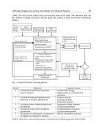
The interconnections among individual Technological Areas identify a chains of codes.
Figure 1 gives an idea of the complexity of the activities and related technological areas
necessary for a such analysis.
Materials &
Components
Dose
Technological areas
Fuel Gap Gas
Cladding
Coolant
Moderator
Pressure vessel
and RCS
Containment
Source term
Estimate Dispersion
Fuel (fuel matrix)
Containment
Thermal Hydraulic
Fuel
Structural
CFD
NK
Dispersion &
dose
Barriers
Fuel
Materials &
Components
Dose
Technological areas
Fuel Gap Gas
Cladding
Coolant
Moderator
Pressure vessel
and RCS
Containment
Source term
Estimate Dispersion
Fuel (fuel matrix)
Containment
Thermal Hydraulic
Fuel
Structural
CFD
NK
Dispersion &
dose
Barriers
Fuel
Fig. 1. Technological areas for the integrated an analysis
The effort to perform a such analysis is aimed to establish a connection with the regulatory
or licensing environment. This connection must take into account the evolution of safety
concepts following improvements of the technical knowledge, including the availability of
powerful computational tools and of experimental evidences.
The framework constitutes by the development & qualification of computational tools is
also related to relevant points like “physical phenomena understanding”, and “analysis of
complex scenarios expected during accident conditions” considering the current licensing
practices.
The strategic objective is the set-up of a suitable chain of codes to deal with accident
scenarios. The motivation for the selection of individual accidents is given by expecting
challenging phenomena for the concerned safety barrier. The concerned phenomena shall
also be connected with the existing code typologies and capabilities. These codes are
Nuclear Power – Operation, Safety and Environment
32
supposed to be qualified for the prediction of individual accidents whose relevant and
detailed boundary and initial conditions have been defined.
The list of phenomena, which are taking place during progression of an accident shall be
analyzed, discussed and selected. Relevant information can be taken from international
literature (e.g. IAEA, 2002) or from experimental tests. The operative objective is to
demonstrate the capability of computational tools to reproduce relevant transient
phenomena and to show that the same tools can be linked together.
Generally speaking, best estimate is associated to the TH SYS codes. About this kind of
codes is clear the meaning of best estimate approach. Descriptions of this concept are largely
diffused in international literature. The concept of best estimate is less clear about the codes
related to the other technological areas. The general concept of best estimate approach is in
avoiding any intentional conservatism. This concept is applied in all the aspects of the
calculation: input data, conditions of the calculation, model of the systems and of course the
code. From this point of view the aspects to be considered for each individual codes are:
The physical modelling.
The approximations that are made and their limitations.
The used correlations.
An assessment of uncertainties due to the physical models.
The practice of application associated to these codes
and their level of validation and/or certification.
the associated impact on the drawing of safety analyses.
In such a complex analysis, requiring different codes, the data used as input for a code are
derived from the result of another previous code calculation. So a relevant role is also
played by the evaluation and selection (as input data in next calculations) of the results
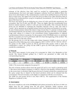
obtained by code application. The figure. 2 gives an idea of the links between the different
technical areas.
Referring to the figure 2, some links are hereafter exemplified.
Path a) the TH codes results are used to supply boundary data to the code for fuel
evaluation.
Path b) the TH codes supply the thermal hydraulic boundary conditions to the NK
codes. The results of the NK codes are supplied to the TH code core component.
Path c) the TH codes supply the thermal hydraulic boundary conditions to the CFD
codes. The results of the CFD codes are supplied to the TH for evaluation of specific
areas of the systems.
Path d) the CFD codes supply the boundary conditions to the Structural code for
evaluation of mechanical resistance of systems components.
Path e) the results from the Containment code are supplied to the TH codes for
calculation of the evolution of the accident in the reactor coolant system and
containment.
Path f) the results of the Structural code about the integrity of the systems (e.g.
containment systems) are supplied to the containment codes.
Path g) the results of the Containment code about possible failure and source terms are
supplied to the codes for dispersion and dove evaluation.
Path h) the results of the Fuel code about source terms are supplied to the codes for
dispersion and dove evaluation.
Integrated Approach for Actual Safety Analysis
33
Materials &
Components
Dose
Technological areas
Fuel Gap Gas
Cladding
Coolant
Mod erator
Pressure vessel
and RCS
Containment
Source term
Estimate Dispersion
Fuel (fuel matrix)
Containment
Thermal Hydraulic
Fuel
Structural
CFD
NK
Dispersion &
dose
a
b
c
d
g
ef
h
Fuel
Materials &
Components
Dose
Technological areas
Fuel Gap Gas
Cladding
Coolant
Mod erator
Pressure vessel
and RCS
Containment
Source term
Estimate Dispersion
Fuel (fuel matrix)
Containment
Thermal Hydraulic
Fuel
Structural
CFD
NK
Dispersion &
dose
a
b
c
d
g
ef
h
Fuel
Fig. 2. Links between the different technical areas
2.2 Qualification and uncertainty
A relevant aspect in best estimate application is the qualification of the process of code
application:
The following specific topics must be covered:
Development process of generic codes and their capabilities;
Developmental Assessment;
Structure of specific codes
Numerical methods;
Description of input decks;
Description of fundamental analytical problems;
Analysis of fundamental problems;
International Standard Problem Activity and benchmarks;
Example of code results from applications to ITF;
Plant accident and transient analyses application;
Modalities for developing the nodalization;
Description and use of nodalization qualification criteria;
Qualitative and quantitative accuracy evaluation;
Use of thresholds for the acceptability of results for the reference case;
Description of the available uncertainty methodologies;
Coupling methodologies.
A specific aspect of best estimate application is constitute by uncertainty evaluation (Wickett
et al., 1998). For the TH codes specific methodologies were developed and applied.
Nuclear Power – Operation, Safety and Environment
34
International literature offers a spread documentation about this uncertainty methodologies
for TH codes.
Concerning the codes not connected with the TH area the following items must be evalauted
to derive the evaluation of the uncertainty.
Description of the numerical methods. Generally the codes are validated versus some
reference calculations and the related uncertainty is also given.
International Standard Problem Activity and benchmarks. From the comparison with
the result of other qualified codes can be estimated the uncertainty of the code.
Code application to experimental tests.
Code application to experimental tests in Plant accident and transient analyses.
Additional and relevant aspects to be also considered are:
Procedure for developing the nodalization developed by the user or in the code manual.
Description and use of nodalization qualification criteria.
User experience
2.3 Computational tools needed in the analysis
The computational tools include:
the best estimate computer codes;
the nodalization including the procedures for the development and the qualification;
the uncertainty methodology including the procedure for the qualification;
the computational platforms for coupling and interfacing inputs and outputs from the
concerned codes and nodalization.
An outline of the codes listed in the table below is provided in the table 1.
No Field of application Example of applications
1. System Thermal-Hydraulics All transients
2. I&C Modelling
All transients (where I & C, i.e.
control, limitation and protection
systems, play a role).
3. Computation Fluid Dynamics
Special detailed analyses of specific
components and/or systems
4. Structural Mechanics
PTS and structural mechanics
integrity of the vessel wall.
5. Fuel (mechanics)
All transients in relation to which the
number of failed rods is calculated
6. Neutron Physics (and supporting)
Transients analyzed by 3D coupled
neutron kinetics - thermal-hydraulics:
spatial or local neutron flux effects
are relevant – transient conditions.
Confinement Severe accident
7.
Radiological Consequences (and
supporting)
Environment diffusion and dose tot
the population
Table 1. Outline of the codes needed in the analysis
Integrated Approach for Actual Safety Analysis
35
All considered codes should be well established within the international community and
some referenced document per each code should be provided that gives access to the
peculiarities of the code.
Key issues for the application of the codes are represented by:
a. the demonstration of the code qualification level;
b. the demonstration of the current user capabilities in the use of the codes.
The quality demonstration of individual codes, item a), can be derived by several hundred
worldwide available documents. In addition to such documents, per each code there are
specific-additional qualification documents issued. The reference document provided per
each code, gives one access to international qualification documents.
Connected with the above item a), the quality of the code application results is increased by
a systematic and comprehensive application of independent codes for deriving the same
result. All the codes should be applied by the users, item b), having experience (years) in the
code application and results analysis. Code qualification cases shall be considered in order
to prove the user capabilities in the application of the codes.
2.3.1 System Thermal-Hydraulics
The quantitative characterization of a system transient scenario constitutes the main role for
the System Thermal-hydraulic (SYS-TH) code, consistently with the main objective for its
development. The SYS-TH code gives the results connected with the thermal hydraulic
parameters evolution of the NPP during a transient. The application of the SYS-TH code,
because of the capability to represent all the systems in a quit compact and fast calculations,
is typically also used to derive the initial conditions for the application of other more specific
codes/tools.
These kinds of codes generally have embedded some additional capabilities:
The multi-dimensional component in SYS-TH code developed to allow the user to more
accurately model the multi-dimensional flow behaviour that can be exhibited in any
component or region of a system.
Neutron kinetic modules: the NK module can have from zero to three dimensions
representation capabilities.
Severe accident module: a limited capability can be included in simulating core damage
occurrence and fission fragment distribution in the systems.
2.3.2 I&C modeling
The aim is to simulate the performance of the control, the limitation and the protection
systems of the NPP. The simplified representation of the protection system only could be
not sufficient for a detailed analysis. The Instrumentation and Control (I&C) can be
modelled in the SYS-TH code. But the complexity of the control (also including limitation)
systems request a more capable end flexible tool. Some applications have been done just
realizing software (e.g. Fortran based software) coupled with the SYS-TH code.
In the I&C software the equations are solved to simulate the transient behaviour of the
various transducers, actuators and logic of operation of each individual component that
constitutes the control, the limitation and the protection systems of the NPP. The code
receives the system information at each time step from the SYS-TH code related to any
requested thermal-hydraulic variable (e.g. pressure, level, pressure drop, fluid temperature).
The related information is processed, e.g. considering the inertia of the transducer or the
Nuclear Power – Operation, Safety and Environment
36
delay of the signal transmission, and commands for components (typically pumps, valves,
control rods, heaters, etc.) modelled in SYS-TH are generated. With the new system
configuration a new time step is calculated and the above process starts again.
2.3.3 Computational Fluid Dynamics
The main role of CFD is to support and validate the application of the SYS-TH in relation to
the mixing phenomena and in calculating pressure drop coefficients at geometric
discontinuities where information from experimental data is not adequate. The latter role is
also relevant to the PTS study.
CFD features the following modelling capabilities:
Steady-state and transient flows.
Laminar and turbulent flows.
Subsonic, transonic and supersonic flows.
Heat transfer and thermal radiation.
Buoyancy.
Non-Newtonian flows.
Transport of non-reacting scalar components.
Multiphase flows.
Combustion.
Flows in multiple frames of reference.
Particle tracking.
2.3.4 Structural mechanics
The structural mechanics code is used to calculate stress and strains in components other
than the fuel rods. Two main uses are exemplified in order to summarize the role of the
code:
a. demonstration that dynamic loads, following transient scenarios, do not cause
rupture/collapse of or the substantial deformation of the relevant component
potentially affecting the coolability of the core;
b. calculation of stresses in the components relevant to prevent radioactive releases.
Typical application is constituted by PTS analysis.
These tools are adopted to perform static and dynamic analyses of linear and non-linear
problems (due to materials properties, geometry, contact between surface, etc.) in many
fields of application (structural, thermal, electromagnetic, fluid-dynamic, etc.). It is possible
to solve coupled problems as well as fluid–structure interaction, thermal–mechanical
calculation. In addition several special purpose features are available, namely: fracture
mechanics, composites, fatigue, beam analyses.
2.3.5 Fuel mechanics
The key goal for the use of the code is the evaluation of the integrity of the fuel claddings.
The number of nuclear fuel rod claddings that are damaged following each transient
constitutes the typical output from the code. The code is a computer program for the
thermal and mechanical analysis of fuel rods in nuclear reactors. The code was specifically
designed for the analysis of a whole rod. Code incorporates physical models of thermal and
radiation densification of the fuel, models of fuel swelling, fuel cracking and relocation, a
model of generation of fission gases, a model of redistribution of oxygen and plutonium,
Integrated Approach for Actual Safety Analysis
37
and some other physical models. The code has the capabilities of analysis of all fuel rod
types under normal, off-normal and accident conditions (deterministic and probabilistic).
2.3.6 Neutron physics
The transient (time dependent) three-dimensional calculation of the neutron flux following
global or local perturbations constitutes the main goal fro the use of the code. The neutron
kinetics subroutines require as input the neutron cross-sections in the computational nodes
of the kinetics mesh. A neutron cross-section model has been implemented that allows the
neutron cross-sections to be parameterized as functions of SYS-TH code heat structure
temperatures, fluid void fraction or fluid density, poison concentration, and fluid
temperatures. Additional codes are necessary to (not exhaustive list):
to derive macroscopic cross sections thus supporting the application of the Nestle code;
to support and to validate calculation results (fluxes and several reaction rates in each
point of the calculation domain and to perform criticality analyses);
to calculate fuel cell calculation versus burn-up;
to calculate the build up, decay, and processing of radioactive materials;
to convert evaluated nuclear data file in continuous-energy or multi-group microscopic
cross sections libraries.
2.3.7 Radiological consequences
The purpose is to simulate the impact of severe accidents at nuclear power plants on the
surrounding environment. The principal phenomena considered are atmospheric transport,
mitigation actions based on dose projections, dose accumulation by a number of pathways
including food and water ingestion, early and latent health effects, and economic costs.
Several aspects must considered:
Calculation of the radioactivity inventory in the fuel elements.
Tracking the transport of radioactivity products inside the primary system and the
containment.
Calculating the offsite radioactivity dispersion and the dose to the population.
Calculating the onsite dispersion and the dose to the control room personnel
2.3.8 Nodalizations
The nodalizations are the result of a brainstorming process by the code-users, which connect
each code with the physical system to be simulated. The process for developing a
nodalization especially for a best estimate code does not necessarily require less effort than
the process of development of the code itself. The same is true in relation to the
qualification. Expert users develop the nodalization for an assigned purpose, provided that
Best Practice Guidelines are followed whenever available. Sensitivity tests can be performed
to demonstrate the nodalization quality and the achievement of mesh-independence of the
results, which means that varying the node density (or the number of nodes) does not make
the results change to a large extent. All nodalizations shall be developed according to
suitable quality assurance procedures and criteria. The procedures are linked with the code
characteristics and with the expertise of the users.
All nodalizations developed to apply the BE codes must be qualified according to current
standards that are specific for each code. Plant nodalization should be developed according
to predefined qualitative and quantitative acceptance criteria.
Nuclear Power – Operation, Safety and Environment
38
Three major steps in the process must be distinguished each one characterized by a number
of sub-steps, by procedures and by acceptability thresholds:
1. Nodalization development: the nodalization must be characterized by ‘geometric
fidelity’ with the modelled physical systems that are part of the NPP.
2. Acceptance of steady state.
3. The transient capability: the capability of the code-nodalization in simulating the
phenomena of interest must be demonstrated
Qualitative and quantitative acceptability thresholds and criteria are adopted at step 1).
Quantitative acceptability thresholds are adopted at step 2). Qualitative and quantitative
accuracy evaluation is performed for step 3) with quantitative thresholds.
A simplified scheme of a procedure for the qualification of the nodalization is depicted in
the figure 3. It is assumed that the code has fulfilled the validation and qualification process
and a “frozen” version of the code has been made available to the final user. The steps of the
diagram are described below.
Code
Code Manual
Code Use Procedure &
Limits
Procedure for
Nodalization
Realization
Nodalization
“Steady State” Level
Qualification
TH & Geometrical
Parameters
“On Transient”
Level Qualification
TH Parameters
and Phenomena
QUALIFIED NODALIZATION
Acceptability
Criteria
Acceptability Criteria
-Qualitative (Ph-W, RTA)
- Quantitative (FFTBM)
a
b
c
d
e
f
g
h
i
j k
l
Fig. 3. Simplified scheme for nodalization qualification
Step “a”:this step is related to the information available by the user manual and by the
guidelines for the use of the code.
Step “b”: user experience and developers recommendations are listed and considered.
Step “c”: the nodalization must reproduce all the relevant parts of the reference plant; this
includes geometrical and materials fidelity and consideration of components and logics.
Step “d”: different checks are performed under this step mostly geometry related (does not
require running the code-nodalization).
Step “e”: different checks are performed under this step.
Integrated Approach for Actual Safety Analysis
39
Step “f”: this is the step where the adopted acceptability criteria are applied to evaluate the
comparison between hardware and implemented geometrical values in the nodalization and
between the experimental and calculated steady-state parameters.
Step “g”: if one of the criteria in the step “f” are not fulfilled, a review of the nodalization
(step “c”) must be performed. The path “g” must be repeated till all acceptability criteria are
satisfied.
Step “h”: this step constitutes the “On Transient” level qualification and allows the
verification of selected data that are relevant only during transient.
Step “i”: in this step the thermal-hydraulic parameters that are at the basis of the qualitative
or quantitative accuracy evaluations are characterized.
Step “j”: checks are performed to evaluate the acceptability of the calculation, e.g. of the ‘Kv-
scaled’ calculation both from qualitative and from quantitative points of view.
Step “k”: this path is actuated if any of the checks (qualitative and quantitative) is not fulfilled.
Step “l”: the obtained nodalization is used for the selected transient and the selected facility
or plant. Any subsequent modification of the nodalization requires a new qualification
process both at “steady state” and at “on transient” level.
3. Example of application: introduction to the analysis of the MPTR
The RBMK core is constituted by more than one-thousand pressurized channels housed into
stacked graphite blocks and connected at the bottom and at the top by small diameter (D)
and long length (L) pipes (less than 0.01 and more than 10 m, respectively) that end up into
headers and drum separators. Control valves are installed in the bottom lines. Due to the
large L/D value and to the presence of valves and other geometric discontinuities along the
lines connecting with the pressure channels, the Fuel Channel Blockage (FCB) event is
possible and already occurred in two documented NPP events. Previous investigations,
have shown the relevance of these events for the safety technology, and the availability of
proper computational technique for the analysis (NIKIET, 1983 and 1992).
The occurrence of the FCB event remains undetected for a few tens of seconds because of the
lack of full monitoring for the individual channels. Therefore, fission power continues to be
produced in the absence of cooling. This brings in subsequent times to fuel rod overheating,
pressure tube failure, damage of the neighbouring graphite brick and ejection of damaged
fuel. Following the pressure tube rupture, reactor cavity pressurization, radioactivity release
into the same area and change of fluid properties occur that allow the detection of the event
and cause the reactor scram at a time of a few tens of seconds depending upon the channel
working conditions and the severity of the blockage.
Notwithstanding the scram and the full capability of the reactor designed safety features to
keep cooled the core, the multiple pressure tube rupture (MPTR) issue is raised. The
question to be answered is whether the ‘explosion’ of the blocked pressure tube damages
not only the neighbour graphite bricks but propagates to other channels causing the
potential for several channel failure.
In order to address the MPTR issue fuel channel thermal-hydraulics and three-dimensional
(3D) neutron kinetics analyses have been performed, as well structural mechanics
calculations for the graphite bricks and rings (graphite rings surround the pressure tube to
accommodate for thermal and radiation induced expansions).
Nuclear Power – Operation, Safety and Environment
40
The bases for the analysis and the results of the study are presented. The conclusion, not
reported within a licensing based format, is that the MPTR consequences are not expected to
be relevant for the safety of the RBMK installations.
3.1 Execution of the analysis
The detailed knowledge of the RBMK system configuration was not spread in the Western
world till the 1986 event. Afterwards, “information batches” of RBMK technology became
available and were unavoidably evaluated in the light of the Chernobyl event. The results of
recently completed project sponsored by European Commission (EC), with the participation
of RBMK designers in Russia and the supervision of the national utility and the regulatory
authority, allow to give an idea of RBMK current safety characteristics. The project has been
made possible owing to the availability of sophisticate computational tools developed and
qualified in the last decade. These include powerful computers, advanced numerical
solution methods, techniques for developing input decks and for proving the qualification
level. Following the identification and the characterization of bounding scenarios assuming
to envelope all accident conditions relevant to RBMK safety technology, two main chains of
codes have been set-up and utilized to perform safety analyses.
3.2 The computational tools
The computational tools include the numerical codes, the nodalizations and the relevant
boundary and initial conditions related to the Smolensk 3 NPP in the present case. The
application of computational tools requires systematic demonstration of quality and suitable
documentation detail. However, within the scope of the performed activity, there is the ‘as-
far-as-possible’ demonstration of quality for codes, the development of nodalizations, the
implementation of boundary and initial conditions as available and the achievement of
results from computer calculations. Furthermore, terms like ‘capable code’ and ‘suitable
code’ have been introduced. A code is ‘capable’ when it is able to simulate the phenomena
and the physical scenarios expected during the assigned NPP accident. A code is ‘suitable’
when a user can run the code addressing (or calculating) the expected phenomena within a
reasonable time with reasonable resources. It should be noted that the term ‘capable’ is less
binding for a code than the term ‘qualified’ and a quantification is provided for the items
‘reasonable resources’ and ‘reasonable time’.
3.3 The numerical codes
The numerical codes adopted are those listed in the third column of Table 2.
Identification
Codes
adopted
Reasons for the selection
No. ACRONYM explanation
A1 LOCA-PH-FIGDH: LOCA in
Pressure Header with failure
to isolate GDH
Relap5 Largest primary system break
with single failure. Challenging
core cooling and the ECCS
design
A2 LOCA-SL: LOCA originated
by a break in Steam Line
Highest depressurization rate.
Challenging core cooling and the
ECCS design
Integrated Approach for Actual Safety Analysis
41
Identification
Codes
adopted
Reasons for the selection
A3 LOOP-ATWS: Loss of on Site
Power with the ATWS
condition
Challenging core cooling and the
neutron kinetics model of the
thermal-hydraulic system codes
A4 GDH-BLOCKAGE: Full
blockage of the GDH
Check of the capability of the
'ECCS bypass' to cool the core
B1 GDH-BLOCKAGE-SA: Full
blockage of the GDH with the
'Severe Accident' assumption
of no bypass line available
Cocosys and
Relap5
Challenging the venting
capability of the reactor cavity
(part of the confinement)
B2 LOCA-PH-FIGDH: See A1 Contain and
Relap5
Challenging the ALS (part of the
confinement) structural
resistance (same as A1)
B3 LOCA-SL: See A2 Contain Challenging the reactor building
(part of the confinement) venting
capability (same as A2)
C1 FC-BLOCKAGE: Full
blockage of one fuel channel
Relap5-
3D©/Nestle
Challenging the calculation of
the local fission power
generation (same as D1)
C2 GDH-BLOCKAGE: See A4 To assess and to understand the
local core response (same as A4)
C3 CR-G-WITHDRAWAL:
Continued withdrawal of a
CR bank (or group)
Korsar-Bars Challenging RIA (Reactivity
Initiating Event)
C4 CPS-LOCA: Voiding (or
LOCA) of the CPS
Relap5-
3D©/Nestle
D1 FC-BLOCKAGE: See C1 Relap5-Ansys
Katran-U-
Stack
Driving accident for the study.
Challenging various areas and
codes
D2 FC-LOCA: Rupture of one FC Contain &
Relap5 Fluent-
Ansys
Korsar-Rapta
To assess the ballooning model
in the fuel pin mechanics area
E1 FC-BLOCKAGE: See C1 Cocos
y
s
Melcor
To assess the hydrogen and the
fission products source term and
transport (same as B1)
E2 GDH-BLOCKAGE-SA: See B1 To assess the hydrogen and the
fission products source term and
transport in one extreme
conditions (same as B1)
F1 FC-BLOCKAGE: See C1 Relap5 To formulate the ICM proposal
(same as D1)
Table 2. Adopted numerical codes
Nuclear Power – Operation, Safety and Environment
42
The area for the application of the codes can be deduced from the second column in the
same table and from the diagrams in figure. 4 and figure 5 that are applicable for the
Russian and the Western codes, respectively. Topological subjects relevant to the
deterministic safety analysis of RBMK are identified in Figs. 4 and 5 and the correspondence
with the range of application of numerical codes is established.
Fig. 4. Codes adopted by Russian group
The topological subjects include:
Five fission product barriers: the fuel pellet, the clad, the pressure boundary of the
primary cooling system and the confinement regions corresponding to the reactor
cavity, the (ALS) and the reactor building.
The materials and components constituting the NPP hardware: the coolant, the fuel and
the moderator are examples of ‘materials’; the control rods, the pressure tube and the
zones of the confinement are examples of ‘components’.
The technological areas (for deterministic safety analysis) include the system thermal-
hydraulics, the computational fluid-dynamics, the structural mechanics, the neutron kinetics
with the cross section generation and the fission product release and transport.
Integrated Approach for Actual Safety Analysis
43
Fig. 5. Codes adopted by western group
3.4 The nodalizations
Nodalizations were developed for both Western and Russian codes by modelling the
materials and components, by making reference to the technological areas and by
considering the features of codes with the target of demonstrating codes capability and
suitability, but also to assess the integrity of the fission product barriers. Nodalizations are
typically the result of wide range brainstorming processes whose outcome depends upon
the code features, the available computer power, the expertise of the user and the target for
the analyses. An example of the realized nodalizations is reported in the table 3.
3.5 The boundary and the initial conditions
Boundary conditions for NPP accident analyses are constituted by huge amount of data
ranging from in the present case the mass of water in the steam drum, to the individual fuel
bundle burn-up, to the material properties of irradiated graphite, to the thickness and the
Young module for the tank that encompasses the graphite stacks, to the free volume of the
reactor cavity, to the net flow areas of the valves/openings connecting various zones of the
confinement with the environment.
The boundary conditions for the MPTR issue is the accident scenario originated by the fuel
channel blockage (FC-BLOCKAGE making reference to boundary conditions in the
Smolensk-3 NPP unit.
3.6 The multidisciplinary problem associated with the FC-BLOCKAGE scenario
The background for addressing the multidisciplinary problem arising from the FC-
BLOCKAGE and the MPTR include the presentation of following aspects: