Applications of High Tc Superconductivity Part 8 pot
Bạn đang xem bản rút gọn của tài liệu. Xem và tải ngay bản đầy đủ của tài liệu tại đây (2.55 MB, 20 trang )
3-D Finite-Element Modelling of a Maglev System
using Bulk High-Tc Superconductor and its Application
129
Step 6: t = t + Δt until the maximum number of time step is achieved, and the steps 2-5 are
repeated.
3.4 Numerical precision
Based on a levitation system composed of a bulk high-Tc superconductor(single-domain
with a cubical shape
)and magnetic rail(assembled by the permanent magnets with
opposite magnetization direction as shown in the inset of Fig. 2
), the dependence of the
computational precision of the levitation force on both mesh density and time step is
discussed in this section. In the calculation, the bulk high-Tc superconductor was
downward in a speed of 1 mm/s from the filed cooling position to the nearest gap, and then
upward to its original position. On the basis of the geometrical and material parameters
listed in Table 2 and power law model, the levitation force of the bulk high-Tc
superconductor was calculated in this vertical down-and-up movement with different mesh
densities and time steps.
w
SC
(mm) l
SC
(mm) t
SC
(mm) J
ab
c
(A/m
2
) E
c
(V/m) U
0
(EV)
α
10 10 10 2.5×10
8
1×10
-4
0.1 3
Table 2. Parameters of high-Tc superconductor used in the calculation for investigating the
numerical precision.
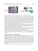
Fig. 2 shows the dependence of the levitation force versus gap curve and the maximum
levitation force
F
max
at the nearest gap on the total finite element node. This figure clearly
illustrates that the levitation force and its hysteresis behavior will approach to a saturated
state with the continuous increment of the total finite element node, or in other words, the
continuous increment of the mesh density. It can be seen from the inset that the
F
max
continuously increases with the total finite element node but the increased rate is gradually
Fig. 2. Levitation force versus gap with different total nodes and the maximum levitation
force
F
max
as a function of the total finite element node (inset).
Applications of High-Tc Superconductivity
130
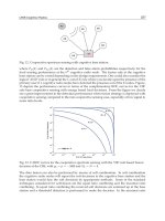
Fig. 3. Levitation force versus gap with different number of time step and the maximum
levitation force
F
max
as a function of the number of time step (inset).
reduced, e.g., the rate of the increment is about 57.1% when the total finite element node is
raised from 27 to 64, but it is only 2.1% when the node is raised from 343 to 512. This
indicates that the computed result is consistent with the finite-element thoery, i.e., the
computed value will approach to the real value with the continuous increment of mesh
density. Fig. 3 plots the levitation force versus gap curve with different number of time steps
and the dependence of the
F
max
on the number of time step. It is obvious that the levitation
force and its hysteresis behavior will also approach to a saturated state with the increment
of the number of time step, e.g., the reduced rate of the
F
max
is less than 0.024% when the
number of time step is raised from 1000 to 2000 and the value of the two cases is almost
identical as shown in the inset of Fig. 3. This indicates that, the approach used to handle the
coupling problem of the governing equations is applicable when the number of time step
adopted is sufficiently large.
4. Experimental validation
The experimental validation is of great importance to support the development of any
theoretical model and to confirm the practical application of the theoretical mode to the real
world. Compared with the previous validations of the model, we will validate the 3-D finite-
element model in a more comprehensive way, i.e., in which two different types of motion
are considered, i.e., vertical movement (perpendicular to the surface of the magnetic rail)
and transverse movement (parallel to the surface of the magnetic rail), are considered, and
the associated magnetic force computed with our model are compared with the
experimental data.
w
SC
(mm) l
SC
(mm) t
SC
(mm) J
ab
c
(A/m
2
) E
c
(V/m) U
0
(eV) ρ
f
(Ωm)
α
30 30 15 1.6×10
8
1×10
-4
0.1 5×10
-10
3
Table 3. Parameters of the high-Tc superconductor used in the calculation for verifying the
3-D finite-element model.
3-D Finite-Element Modelling of a Maglev System
using Bulk High-Tc Superconductor and its Application
131
4.1 Brief introduction of the experiment
The self-developed maglev measurement system was used to measure the magnetic force of
the bulk high-Tc superconductor (Wang, 2010). The Y-Ba-Cu-O sample used here is of
single-domain with a rectangular shape, and its geometrical parameters and photo as well
as its schematic drawing are presented in Table 3 and Fig. 4 respectively. The geometric
parameters and photos of the two magnetic rail demonstrators (Rail_1 and Rail_2) used to
generate the applied field for high-Tc superconductor are also shown in Fig. 4.
In the experiment, the sample was firstly bath-cooled in a liquid nitrogen vessel for several
minutes to to insure the superconductive state was established at a certain position above
the center of the magnetic rail, and then, for the vertical movement, the sample was put
downward to an expected nearest gap (distance from the bottom of the high-Tc
superconductor to the upper surface of the magnetic rail) and then upward to its original
position in the levitation case, whereas in the suspension case, the movement was opposite;
For the transverse movement, the sample was put downward (levitation case) or upward
(suspension case) to its levitation height, and then it was forced to move along the
transverse direction parallel to the surface of the magnetic rail (
y-axis shown in Fig. 1) after a
30 seconds’ relaxation at the levitation height to reduce the influence of the force relaxation
on the subsequent measurement or calculation. The experimental and computed speed was
chosen to be 1 mm/s in all cases and the maximum lateral displacement for traverse
movement was 5 mm.
Fig. 4. Photos of the Y-Ba-Cu-O sample and magnetic rail demonstrators and associated
schematic drawings of magnetic rail’s cross sections.
4.2 Experimental validation of the computed results
In the calculation, the magnetic rail were calculated by a 3-D analytical model in which the
finite geometry of each magnet used in the magnetic rail is taken into account (Ma, et al.,
2009). With the restriction of the available experimental tools, the material parameters
involved in the
E–J relation and the angular-dependence of the critical current density
formulation can not be directly measured. In the following calculation, the necessary
material parameters were determined according to the published literatures. The reported
values of the pinning potential
U
0
and flow resistivity ρ
f
are very scattered. Here, pinning
potential and flow resistivity were chosen to be 0.1 eV and 5×10
-10
Ωm respectively. Both of
them are the frequently used values in the calculation Gou, et al.,2007a; Gou, et al.,2007b;
Yoshida, et al., 1994). The anisotropic ratio for the melt-processed-single-domain Y-Ba-Cu-O
has been measured to be
~3 at 77 K (Murakami, et al., 1991). Critical current density in the
Applications of High-Tc Superconductivity
132
ab-plane J
ab
c
, was determined by fitting one of the levitation force versus gap curve (the first
curve in the following Fig. 7). In addition, Kim’s model (Kim, et al., 1962) was also
employed to describe the field amplitude dependence characteristic of the critical current
density in the calculation. All the parameters of the Y-Ba-Cu-O were summarized in Table 3.
4.2.1 Numerical results with different E-J constitutive relations and angular-
dependence of critical current density formulas
Firstly, we evaluated the levitation force versus gap behavior with different angular-
dependence of the critical current density formulations and
E–J constitutive relations. In the
3-D finite-element model, the three different components of the magnetic force, i.e., vertical
force perpendicular to the surface of the magnetic rail (
z-axis), transverse force along the
magnetic rail’s width (
y-axis) and longitudinal force along the magnetic rail’s length (x-axis)
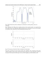
can be calculated. From the computed results presented in Fig. 5, we can see that, there is no
noticeable discrepancy among the computed levitation force for different test cases. This
indicates that there is almost no difference between the power law model and flux flow and
creep model when the pining potential
U
0
and operating temperature are identical (the
index
n in power law model is ~ 15 at liquid nitrogen temperature with the pinning
potential presented in Table 3). Moreover, the elliptical model is also viable to describe the
anisotropic behavior of the high-Tc superconductor. Furthermore, as expected, the
transverse force and longitudinal force shown in the inset of Fig. 5 are almost zero all the
time with the variation of the gap because the applied field is symmetrical along the
longitudinal and transverse directions of the magnetic rail.
In the following calculation, we choose the elliptical model for the purpose of introducing a
new way to describe the anisotropic behavior of the critical current density and power law
model to describe the
E–J constitutive relation of the high-Tc superconductor because it seems
to be more numerically stable to converge when compared to the flux flow and creep model.
Fig. 5. Comparison of levitation force versus gap curve between different
E–J constitutive
relations and angular-dependent of the critical current density formulations as well as the
transverse and longitudinal force versus gap behavior with power law and elliptical model
(inset). The applied field was provided by Rail_1 shown in Fig. 4.
3-D Finite-Element Modelling of a Maglev System
using Bulk High-Tc Superconductor and its Application
133
Fig. 6. Comparison of the levitation force versus gap curve between the computed results
and measured results under vertical movement in the applied field generated by Rail_1
shown in Fig. 4. The Y-Ba-Cu-O was bath-cooled at a position which was 60 mm above the
rail where the applied field is weak and so this case can be approximately considered as
zero field-cooled condition.
4.2.2 Comparison of the levitation force under vertical movement
The vertical force of the Y-Ba-Cu-O above the center of the magnetic rail1 with different
field-cooled positions was calculated and compared with the measured data. From the
compared results presented in Figs. 6-8, we can see that, the computed results agree well
with the measured results in both hysteresis loop as well as detailed values at a certain gap.
For the levitation case shown in Figs. 6-7, we can find from both the computed and
measured results that, on the downward branch of the levitation force versus gap curve, the
levitation force and slope of the curve are continuously enhanced with the decrease of the
gap. For the same gap, the levitation force of the downward branch is always larger than
that of the upward branch, and this reveals an obvious hysteresis behavior of the levitation
force. Furthermore, the levitation force versus gap behavior was calculated and measured
another two times after the first one for the field-cooled test case at 25 mm above the
magnetic rail1. It can be seen clearly that the computed results also compare well with the
measured data for the second time and third time. This further confirms the validation of
the 3-D finite-element method.
For the suspension test case shown in Fig. 8, the suspension force versus gap curve of both
computed and measured cases indicates that, according to the stiffness defined in (Hull,
2000), the suspension force increases with the gap and its stiffness is always positive before
the maximum absolute value of the suspension force is achieved at a certain gap. Therefore,
the suspension system is always stable within this gap. The suspension force will decrease
when the gap is further increased and the suspension system becomes unstable. Also, there
is a clear hysteresis behavior of the suspension force by comparing the upward and
downward branch of the curve. In addition, we also presented the computed results with
flux flow and creep model, and the good agreement between the results of power law model
and flux flow and creep model demonstrates that, the two
E–J constitutive relations are also
identical for the suspension case.
Applications of High-Tc Superconductivity
134
Fig. 7. Comparison of the levitation force versus gap curve between the computed results
and measured results under vertical movement in the applied field generated by Rail_1
shown in Fig. 4. The Y-Ba-Cu-O was bath-cooled at a position of 25 mm above the rail which
was a typical field-cooled condition. The levitation force versus gap curve was calculated
and measured with continous three times here.
Fig. 8. Comparison of the suspension force versus gap curve between the computed results
and measured results under vertical movement in the applied field generated by Rail_1
shown in Fig. 4. The Y-Ba-Cu-O is bath-cooled at a position of 8 mm above the rail.
Fig. 9. Comparison of the magnetic force as a function of lateral displacement between the
computed and measured results under transverse movement in the applied field generated by
Rail_2 shown in Fig. 4. The Y-Ba-Cu-O sample was field-cooled at a position of 30 mm, and the
levitation gap where the magnetic force was calculated or measured was 18 mm above the rail.
3-D Finite-Element Modelling of a Maglev System
using Bulk High-Tc Superconductor and its Application
135
4.2.3 Comparisons of the magnetic force under transverse movement
In order to verify the robustness of the performance of the 3-D finite-element model, the
Rail_2 shown in Fig. 4, which is a Halbach array (Halbach, 1985), was employed to produce
the applied field in this section.
During the transverse movement, both the vertical force and transverse force are a function
of the lateral displacement. The compared results between the numerical results and
measured results for different cases, i.e., levitation case with field-cooled above the
levitation position, field-cooled at the levitation position, and suspension case with field-
cooled below the suspension position, are presented in Figs. 9-11, respectively.
Both the numerical results and measured results shown in Figs. 9-11 indicate that, the
absolute value of the transverse force increases with the lateral displacement and the
Fig. 10. Comparison of the magnetic force as a function of lateral displacement between the
computed and measured results under transverse movement in the applied field generated
by Rail_2 shown in Fig. 4. The Y-Ba-Cu-O sample was field-cooled at the identical height (18
mm) with the levitation height where the magnetic force was calculated or measured.
Fig. 11. Comparison of the magnetic force as a function of lateral displacement between the
computed and measured results under transverse movement in the applied field generated
by Rail_2 shown in Fig. 4. The Y-Ba-Cu-O sample is field-cooled at a position of 13 mm,
which was below the levitation gap (18 mm) where the magnetic force was calculated or
measured.
Applications of High-Tc Superconductivity
136
direction of the transverse force is opposite to the transverse movement, which indicates
an inheret stable levitation can be acquired. Also, the magnetic force (i.e., the vertical force
and the transverse force) are hysteretic as a function of the lateral displacement. Despite
that the compared results of the transverse case is not as good as that of vertical case, as a
whole, the numerical results are well comparable to the measured results in quality
especially for the suspension case shown in Fig. 11. The fitting value of the critical current
density in the
ab-plane J
ab
c
was derived from the case above the Rail_1 and the shift of the
applied field are likely to be responsible for the discrepancy between the computed and
measured results.
5. Optimization of the magnetic rail using the 3-D finite-element model
Magnetic rail is a key component to privide the applied magnetic field for the present
magnet levitation system using bulk high-Tc superconductor, and the cost spend in building
the magnetic rail occupies most part of the entire investment because the magnetic rail is
required along the whole line. It is thereby meaningful to optimize the structure and
geometric parameters of the magnetic rail in the purpose of getting a magnetic rail that
holds the required levitation capability with a reduced cost. In this aspect, a lot of previous
work has been reported and the dependence of the levitation force/guidance force on the
parametes of the magnetic rail has been invesigated. However, all of these results were
concluded from the numerical data calculated by a 2-D model that can just fit the
experimental results in quality but fails in quantity with a reasonable value of critical
current density (Song, et al., 2006; Dias, et al., 2010).
w
SC
(mm)l
SC
(mm)t
SC
(mm)
J
ab
c
(A/m
2
)E
c
(V/m)U
0
(EV)
α
42 21 9 2.5×10
8
1×10
-4
0.1 3
Table 4. Parameters of high-Tc superconductor used in the calculation for obtaining an
optimized magnetic rail.
Fig. 12. Two different magnetic rails with five permanent magnets derived from the Halbach
array
3-D Finite-Element Modelling of a Maglev System
using Bulk High-Tc Superconductor and its Application
137
Fig. 13. Chart of the the maglev system with three bulk Y-Ba-Cu-O undergoing the vertical
or transverse movement above the rail
In this section, basing on the 3-D finite-element model introduced in this chapter, we
calculate the levitation force and guidance force of three Y-Ba-Cu-O bulks samples above
two differnt magnetic rails deriving from the traditional Halbach array. The geometric
parameters of magnetic rail such as height, width are variable in the calculation, and then
the depedence of levitation capability of the bulk Y-Ba-Cu-O on those parameters was
studied. Compared with the previous work, the merit of the present calculation is that, the
computed levitation force/guidance force is comparable to the real system with reasonable
vaule of the critical current density and thus, the computed results can be used to conduct
the practical design directly.
The geometric and material parameters of the Y-Ba-Cu-O sample were shown in Table 4 The
speed of the samples in both vertical and transverse direction is 1 mm/s and the
magnetization
M
0
of the permanent magnet employed to assemble the magnetic rail is
8.9×10
5
A/m in all cases.
As for the structure of the magnetic rail, Halbach array is a better choice than the original
type used in the high-Tc superconducting maglev train demonstrator because this structure
can concentrate the magnetic field to its upper space where the high-Tc superconductors are
placed, and thus can improve the utilization of the magnetic field (Jing, 2007). From the
basic structure of the Halbach array shown in Fig. 12, we can derive two different types of
magnetic rail, i.e., one has three permanent magnets magnetized in the horizontal direction
and two permanent magnets magnetized in the vertical direction, the other has three
permanent magnets magnetized in the vertical direction and two permanent magnets
magnetized in the horizontal direction. These two magnetic rails derived from the Halbach
array are presented in Fig. 12.
In the calculation, we ignore the possible interaction among the Y-Ba-Cu-O samples for
simplicity, and calculate only two samples beacuse of the symmetry of the levitation system
shown in Fig. 13. In the default case, the high-Tc superconductors were field-cooled at a
position of 30 mm above the surface of the magnetic rail for the calculation of the levitation
force, and for the calculation of the guidance force, the tranverse movement occurs at the
same height as the field-cooled position, that was 12 mm above the surface of the magnetic
rail. The main parameters that should be optimized in the two structure, i.e., Rail_A and
Applications of High-Tc Superconductivity
138
Rail_B shown in Fig. 12, are the ratio between the width of two different magnetized
magnets, the width of and the height of the magnetic rail. The following section shows the
computed results of the optimization by varying those parameters.
5.1 Width ratio of the two different magnetized magnets
In this section, the levitation force and guidance force on the high-Tc superconductors with
the variation of the width ratio, i.e.,
w
A1
/w
A2
for Rail_A or w
B1
/w
B2
for Rail_B, were
calculated. In this calculation, the total width and the height of both rails were assumed
respectively to be 130 mm and 30 mm and invariant with the change of the width ratio. For
simplicity in drawing the following figures, the width ratio was replaced by an order and
the corresponding relationship between the width ratio and the order was given in Table. 5.
Order
1 2 3 4 5 6 7 8 9 10 11
12 13 14 15 16 17 18 19 20 21
Width
ratio
0 0.01 0.1 0.16667 0.25 0.333333 0.4 0.5 0.66667 0.83 1
1.22 1.5 2 2.5 3 4 6 10 100 ∞
Table 5. Corresponding relationship between the width ratio and the order in optimazing
the width ratio of the magnetic rails.
For the case of vertical movement, twenty-one different width ratios from zero to infinity were
considered and the changing curve of the levitation force along with the width ratio at position
of 5, 10, 15 and 20 mm above the Rail_A and the Rail_B was shown respectively in Fig. 14(a)
and Fig. 14(b). Note that the extreme case with a width ratio of zero or infinity denotes that
Halbach struture disappears and permanent magnets employed in the Rail only have one
magnitized direction (vertical or horizontal direction). Both Fig. 14(a) and Fig. 14(b) display
that, the levitation force, at all positions we presented, increases with the growth of the width
ratio and reaches to a maximum value when the width ratio was
~0.83 for Rail_A and was
~1 for Rail_B and then drops with continuous growth of the width ratio. This finding
indicates, the halbach array has a better performance because the levitation
Fig. 14. The changing curve of the levitation force on the high-Tc superconductors at
position of 5, 10, 15 and 20 mm above the Rail_A (a) and Rail_B (b) with the growth of the
width ratio. The width ratio is replaced by an order and the corresponding relationship
between the width ratio and the order (abscissa) is given in Table. 5.
3-D Finite-Element Modelling of a Maglev System
using Bulk High-Tc Superconductor and its Application
139
Fig. 15. The changing curve of the guidance force on high-Tc superconductors at a lateral
displacement of 6 mm with the growth of the width ratio. The corresponding relationship
between the width ratio and the order (abscissa) can be found in Table. 5. The total number
of width ratio considered in this calculation was reduced and thus the order starts at 6 and
ends at 16 .
force at the extreme case is always the smallest one as has been verified by experiment (Jing, et
al., 2007; Sotelo, et al., 2010), on the other hand, the optimized struture for Rail_A is that the
width of magnet magnetized in horizontal direction is slightly larger than that magnetized in
vertical direction, but for Rail_B, the two type magnets have an identical width ratio.
For the case of the transverse movement, only eleven different width ratios around 1 were
considered because larger levitation force can be obtained in that area according to the
above computed results of levitation force. The high-Tc superconductors have a field-cooled
height of 12 mm and then were drived transversely at the same height with a maximum
lateral displacement of 6 mm. Fig. 15 presents the guidance force with respect to the width
ratio for the Rail_A and the Rail_B. We can find from this figure that, the guidance force
exhibits a same tendency with the growth of the width ratio as that found in the case of
levitation force, but the width ratio where the largest guidance force occurs is found to be
1.22
~1.5 for Rail_A and is still ~1 for Rail_B.
As a whole, we suggest that, for the Halbach array as the magnetic rail used in the maglev
train, the optimized width ratio between the vertical and transverse magnetized magnet
is
~1.
5.2 Total width of the magnetic rail
In this calculation, the total width of both rails was a variable parameter with a fixed height
of 30 mm and a fixed width ratio of 1.
Fig. 16 shows the changing curve of the levitation force on the high-Tc superconductors at
positions of 5, 10, 15 and 20 mm above the Rail_A and Rail_B with the growth of the total
width from 60 mm to 170 mm. These figures show that, with the increase of the position, the
total width where the maximum value of the levitation force appears is shift from small to
large value, e.g., the levitation force increases almost linearly with the total width at the
position of 20 mm for both rails and the maximum value of the levitaion force even does not
appear within our calculational range. This figure also indicates that, the increase of the total
width does not always bring an ehencement of the levitation force especially for the case at a
Applications of High-Tc Superconductivity
140
Fig. 16. The changing curve of the levitation force on the high-Tc superconductors at
positions of 5, 10, 15 and 20 mm above the Rail_A (a) and Rail_B (b) with the growth of the
total width. The total width was varied from 60 to 170 mm.
Fig. 17. The changing curve of the guidance force on the high-Tc superconductors at a lateral
placement of 6 mm with the growth of the total width. The total width was varied from 60
to 170 mm.
low position. Of course, if a larger levitaion capability is required at a high position, it is a
viable way to lengthen the total width of the rail. For the typical position of 15 mm in the
maglev train, it seems that, the optimized value of the total width appears around 130 mm
for both rails because the slope of the curve begins to dcrease at this value.
Fig. 17 shows the changing curve of the guidance force on the high-Tc superconductors at a
lateral displacement of 6 mm with the growth of the total width from 60 to 170 mm. From
this figure, we can find that, the guidance force also increases firstly and then decreases with
the growth of the total width, and the maximum value of the guidance force occurs around
120 mm for Rail_A and around 135 mm for Rail_B. Although the total width where the
maximum value of the guidance force occurs is scattered above Rail_A and Rail_B, the
variation of the guidance force above both rails in the range of 120
~140 mm is not evident.
It is therefore this range can be considered as the optimized range which is comparable to
3-D Finite-Element Modelling of a Maglev System
using Bulk High-Tc Superconductor and its Application
141
the total width of the high-Tc superconductors (126 mm) in determining the total width of
the rail for a practical design.
5.3 Height of the magnetic rail
The height of the magnetic rail is another factor influencing the levitation capability of the
high-Tc superconductor. Here, we fixed the width ratio to be 1 and total width to be 130
mm, and varied the height of the magnetic rail from 15 mm to 100 mm. The levitation forces
above the Rail_A and Rail_B were plotted as a function of the height and the associate
curves were given in Fig. 18. This figure displays clearly that, no matter the position where
the high-Tc superconductors are placed, the levitation force increases drastically at first and
then goes into gradually a saturated state with heightening the rail. This phenomenon
indicates that, considering the cost of the rail, it is not reasonable to get a better levitation
performance by increasing the height of the rail when the height is already high enough.
Fig. 18. The levitation force versus height of the Rail_A (a) and of the Rail_B (b). The height
of both rails were varied from 15 to 100 mm.
6. Conclusion remarks
On the basis of Maxwell’s equations and Helmholtz’s theorem, the 3-D governing equations
containing the anisotropic behavior of the HTS were deduced at length by introducing a
current vector potential
T and a simplified expression of the resistivity tensor for the high-
Tc superconductor. The two common models to handle the highly nonlinear
E–J
characteristic, i.e., power law model and flux flow and creep model, were presented and, the
critical current density
J
c
as a function of the angle φ between the orientation of the applied
field and the
c-axis of the high-Tc superconductor, was expressed by an elliptical model. The
discrete matrix of the 3-D governing equations was derived by utilizing the Galerkin’s
finite-element method and the Crank-Nicolson-
θ method to numerically treat the governing
equations one by one in space and time domain respectively. The corresponding nonlinear
algebraic equations of the discrete matrix were effectively resolved by incorporating the
Newton-Raphson method with an extended format of the Incomplete Cholesky-Conjugate
Gradientmethod.
The computed results of the levitation force of a bulk high-Tc superconductor above a
magnetic rail indicate that, the levitation force and associated hysteresis behavior will
Applications of High-Tc Superconductivity
142
approach to a saturated state with the increment of the mesh density or the number of the
time steps. This result is consistent with the finite-element theory, and also, supports the
approach used to simplify the coupling problem between the differential and integral term
presented in the governing equations.
Subsequentely, the 3-D finite-element model was validated by comparing the computed
magnetic forces of a bulk Y-Ba-Cu-O sample with the measured data under vertical and
transverse movements. Basing on the 3-D finite-element model, we also found that, the
computed results of magnetic force of the high-Tc superconductor are almost identical for
different angular-dependence of critical current density formulations (i.e., Yang’s model and
elliptical model) and
E–J constitutive relations (i.e., power law model and flux flow and
creep model).
Lastly, using this 3-D finite-element model, we conduct a preliminary numerical work
with aim of geting an optimized geometric parameter of the magnetic rails derived from
the Halbach array. The results show that, when the width ratio of the two different
magnetized magnets used in the magnetic rail is approximately identical and the total
width of the rail is roughly indentical to the width of the high-Tc superconductors, the rail
exhibits a better performance in considering both the levitation capability and the cost (be
proportional to the voulme of the rail). Moreover, the levitation force has a saturated
tendency with increasing continuely the height of the rail, so it is not reasonable to get a
better levitation performance by increasing the height of the rail when the height is
already high enough.
7. Acknowledgments
This work was supported by the National Natural Science Foundation of China under Grant
51007076 and 50777053, and the Innovation Foundation of Southwest Jiaotong University for
Ph.D. Candidate. The authors would like to thank Dr. Frank N. Werfel of the Adelwitz
Technologiezentrum GmbH (ATZ) for providing the Y-Ba-Cu-O sample employed in the
experiment and to thank Dr. Hong-Hai Song, Dr. Zi-Gang Deng, Dr. Yi-Yun Lu, Dr. Min-
Xian Liu, Dr. Jun Zheng, Dr. Fei Yen, Mr. Wei Liu, Mr. Qun-Xu Lin, Mr. Dong-Hui Jiang for
their many fruitful discussions
8. References
Alloui, L. & Bouillault, F. & Mimoune, S. M. (2009). Numerical study of the influence of
flux creep and of thermal effect on dynamic behaviour of magnetic levitation
systems with a high-Tc superconductor using control volume method.
Eur. Phys.
J. Appl. Phys.
, Vol. 45, pp. 20801
Alonso, D. R. & Coombs, T. A. & Campbell, A. M. (2004). Numerical analysis of high-
temperature superconductors with the critical-state model.
IEEE Trans. Appl.
Supercond.
, Vol. 14, No. 4, pp. 2053–2063.
Anderson, P. W. (1962). Theory of flux creep in hard superconductor.
Phys. Rev. Lett., Vol.
9, No. 7, pp. 309–311
Bean, C. P. (1964). Magnetization of high-field superconductors.
Rev. Mod. Phys., vol. 36,
pp.31–39
3-D Finite-Element Modelling of a Maglev System
using Bulk High-Tc Superconductor and its Application
143
Brandt, E. H. (1989). Levitation in physics. Science, vol. 243, pp. 349–355
Brandt, E. H. (1996). Superconductors of finite thickness in a perpendicular magnetic field:
Strips and slabs.
Phys. Rev. B, Vol. 54, No. 6, pp. 4246–4264
Cui, X. (1989). A new preconditional conjugate gradient algorithm.
Journal of North China
Institute of Electric Power
, No. 2, pp. 1–8, (in Chinese)
Davis, L. C. & Logothetis, E. M. & Soltis, R. E. (1988). Stability of magnets levitated above
superconductors.
J. Appl. Phys., Vol. 64, No. 8, pp. 4212–4218
Dias, D. H. N. & Motta, E. S. & Sotelo, G. G. & Andrade Jr, R. D. (2010). Experimental
validation of field cooling simulations for linear superconducting magnetic
bearings.
Supercond. Sci. Technol. Vol. 23, pp. 075013
Dinger, T. R. & Worthington, T. K. & Gallagher, W. J. & and Sandstrom, R. L. (1987).
Direct observation of electronic anisotropy in single-crystal Y
1
Ba
2
Cu
3
O
7-x
. Phys.
Rev. Lett.
, Vol. 58, pp. 2687–2690
Fujiwara, K. & Nakata, T. & Fusayasu, H. (1993). Acceleration of convergence
characteristic of the ICCG method.
IEEE Trans. Magn., Vol. 29, No. 2, pp. 1958–
1961
Gou, X. F. & Zheng, X. J. & Zhou, Y. H. (2007a). Drift of levitated/suspended Body in
high-
T
c
superconducting levitation systems under vibration—part I: A criterion
based on magnetic force-gap relation for gap varying with time.
IEEE Trans. Appl.
Supercond.
, Vol. 17, No. 3, pp. 3795–3802
Gou, X. F. & Zheng, X. J. & Zhou, Y. H. (2007b). Drift of levitated/suspended Body in
high-
T
c
superconducting levitation systems under vibration—Part II: drift
velocity for gap varying with time.
IEEE Trans. Appl. Supercond., Vol. 17, No. 3,
pp. 3803–3808
Grilli, F. & Stavrev, S. & Le Floch, Y. & Costa-Bouzo, M. & Vinot, E. & Klutsch, I. &
Meunier, G. & Tixador, P. & Dutoit, B. (2005). Finite-element method modeling
of superconductors: from 2-D to 3-D.
IEEE Trans. Appl. Supercond., Vol. 15, No. 1,
pp. 17–25
Halbach, K. (1985). Application of permanent magnets in accelerators and electron storage
rings (invited).
J. Appl. Phys., Vol. 57, pp. 3605–3908
Hashizume, H. & Sugiura, T. & Miya, K. & Ando, Y. & Akita, S. & Torii, S. & Kubota, Y. &
T. Ogasawara. (1991). Numerical analysis of a. c. losses in superconductors.
Cryogenics, Vol. 31, pp. 601–606
Hull, J. R. & Cansiz, A. (1999). Vertical and lateral forces between a permanent magnet
and a high-temperature superconductor.
J. Appl. Phys., Vol. 86, No. 11, pp. 6396–
6404
Hull, J. R. (2000). Superconducting bearings.
Supercond. Sci. Technol., vol. 13, pp. R1–R15
Jing, H. & Wang, J. & Wang, S. & Wang, L. & Liu, L. & Zheng, J. & Deng, Z. & Ma, G. &
Zhang, Y. & Li
. J. (2007). A two–pole Halbach permanent magnet guideway for
high temperature superconducting Maglev vehicle.
Physica C. 2007, Vol. 463–465,
pp. 426–430
Kershaw, D. S. (1978). The incomplete cholesky–conjugate gradient method for the
iterative solution of systems of linear equations.
Journal of Computational Physics,
Vol. 26, pp. 43–65
Applications of High-Tc Superconductivity
144
Kim, Y. B. & Hemptead, C. F. & Strnad, A. R. (1962). Critical persistent currents in hard
superconductors.
Phys. Rev. Lett., Vol. 9, No. 7, pp. 306-309
Kordyuk, A. A. (1998). Magnetic levitation for hard superconductor.
J. Appl. Phys., Vol. 83,
No. 1, pp. 610–612
Krusin-Elbaum, L. & Malozemoff, A. P. & Yeshurun, Y. & Cronemeyer, D. C. & Holtzberg,
F. (1989). Temperature dependence of lower critical fields in Y-Ba-Cu-O crystals.
Phys. Rev. B, Vol. 39, No. 4, pp. 2936–2939
Lu, Y. Y. & Wang, J. S. & Wang, S. Y. & Zheng J., (2008). 3D-Modeling numerical solutions
of electromagnetic behavior of HIGH-TC SUPERCONDUCTORC bulk above
permanent magnetic guideway.
J. Supercond. Nov. Magn., Vol. 21, pp. 467–472
Luo, Y. & Takagi, T. & Miya, K. (1999). Reduction of levitation decay in high Tc
superconducting magnetic bearings.
Cryogenics, Vol. 39, pp. 331–338
Ma, G. T. & Liu, H. F. & Wang, J. S. & Wang, S. Y. & Li, X. C. (2009). 3D modeling
permanent magnet guideway for high temperature superconducting maglev
vehicle application.
J. Supercond. Nov. Magn., Vol. 22, pp. 841–847
Ma, K. B. & Postrekhin, Y. V. & Chu, W. K. (2003). Superconductor and magnet levitation
devices.
Rev. Sci. Instrum., Vol. 74, No. 12, pp. 4989–5017
Matsushita, T. (2007).
Flux Pinning in Superconductors. Springer-Verlag Berlin, pp. 365-366.
Mikitik, G. P. & Brandt, E. H. (2000). Critical state in thin anisotropic superconductors of
arbitrary shape.
Phys. Rev. B, Vol.62, pp. 6800–6811
Miya, K. & Hashizume, H. (1988). Application of T-method to A.C. problem based on
boundary element method.
IEEE Trans. Magn., Vol. 24, No. 1, pp. 134–137
Murakami, M. & Oyama, T. & Fujimoto, H. & Gotoh, S. & Yamaguchi, K. (1991). Melt
processing of bulk high Tc superconductors and their application.
IEEE Trans.
Magn.
, Vol. 27, No. 2, pp. 1479–1486
Napoli, A. D. & Paggi, R. (1983). A model of anisotropic grain-oriented steel.
IEEE Trans.
Magn.
, Vol. 19, No. 4, pp. 1557–1561
Navau, C. & Sanchez, A. (2001). Magnetic properties of finite superconducting cylinders.
II. Nonuniform applied field and levitation force.
Phys. Rev. B, Vol. 64, pp. 214507
Pecher, R. & McCulloch, M. D. & Chapman, S. J. & Prigozhin, L. & Elliot, C. M. (2003) 3D-
Modelling of bulk type-II superconductors using unconstrained H-formulation.
EUCAS 2003, Sorrento, Italy, Sep. 14–18
Prigozhin, L. (1997). Analysis of Critical-State Problems in Type-II Superconductivity,”
IEEE Trans. Appl. Supercond., Vol. 7, No. 4, pp. 3866–3873
Qin, M. J. & Li, G. & Liu, H. K. & Dou, S. X. & Brandt, E. H. (2002). Calculation of the
hysteretic force between a superconductor and a magnet.
Phys. Rev. B, Vol. 66,
pp. 024516
Rhyner, J. (1993). Magnetic properties and AC–losses of superconductors with power law
current–voltage characteristics.
Physica C, Vol. 212, pp. 292–300
Sanchez, A. & Navau, C. (2001). Magnetic properties of finite superconducting cylinders.
I. Uniform applied field.
Phys. Rev. B, Vol. 64, pp. 214506
Sanchez, A. & Valle, N. D. & Pardo, E. & Chen, D. X. & Navau, C. (2006). Magnetic
levitation of superconducting bars.
J. Appl. Phys., Vol. 99, pp.113904
3-D Finite-Element Modelling of a Maglev System
using Bulk High-Tc Superconductor and its Application
145
Sawamura, M. & Tsuchimoto, M. (2000). Numerical analysis for superconductor in sheet
and bulk form,”
Japan J. Indust. Appl. Math., Vol. 17, No. 2, pp. 199–208
Schultz, L. & Haas, O. & Verges, P. & Beyer, C. & Röhlig, S. & Olsen, H. & Kühn, L. &
Berger, D. & Noteboom, U. & Funk, U. (2005). Superconductively levitated
transport system-the SupraTrans project.
IEEE Trans Appl. Supercond., Vol. 15,
No.2, pp. 2301–2305
Song, H. H. & Wang, J. S. & Wang, S. Y. & Ren, Z. Y. & Wang, X. R. & Haas, O. & Fuchs,
G. & Schultz, L. (2006). Studies of YBCO electromagnetic properties for high-
temperature superconductor maglev technology. in
New Topics in
Superconductivity Research
, Barry P. Martins Ed., New York: Nova Science
Publishers, pp. 107–156
Sotelo, G. G. & Dias, D. H. N. & Andrade Jr, R. D. & Stephan, R. M. (2010). Tests on a
Superconductor Linear Magnetic Bearing of a Full-Scale MagLev Vehicle.
IEEE
Trans. Appl. Supercond.
, doi: 10.1109/TASC.2010.2086034, (in press)
Takagi, T. & Sugiura, T. & Miyata, K. & Norimatsu, S. & Okamura, K. & Miya, K. (1988).
Iterative solution technique for 3-D eddy current analysis using T-method.
IEEE
Trans. Magn.
, Vol. 24, No. 6, pp. 2682–2684
Ueda, H. & Azumaya, S. & Tsuchiya, S. & Ishiyama, A. (2006). 3D electromagnetic
analysis of levitating transporter using bulk superconductor.
IEEE Trans. Appl.
Supercond.
, Vol. 16, No. 2, pp. 1092–1095
Uesaka, M. & Yoshida, Y. & Takeda, N. & Miya, K. (1993). Experimental and numerical
analysis of three-dimensional high-
T
c
superconducting levitation systems. Int. J.
Appl. Electromagn. Mater.
, Vol. 4, pp. 13–25
Wang, J. S. & Wang, S. Y. & Zeng, Y. W. & Huang, H. Y. & Luo, F. & Xu, Z. P. & Tang, Q.
X. & Lin, G. B. & Zhang, C. F. & Ren, Z. Y. & Zhao, G. M. & Zhu, D. G. & Wang,
S. H. & Jiang, H. & Zhu, M. & Deng, C. Y. & Hu, P. F. & Li, C. Y. & Liu, F. & Lian,
J. S. & Wang, X. R. & Wan, L. H. & Shen, X. M. & Dong, X. G. (2002). The first
man-loading high temperature superconducting maglev test vehicle in the world.
Physica C, Vol. 378-381. pp.809-814
Wang, J. S. & Wang, S. Y. (2010).
High Temperature Superconducting Maglev Measurement
System
. In: Milind Kr Sharma Ed., Advances in Measurement Systems, pp. 51-80
Wu, J. Z. & Hsieh, P. Y. & McGuire, A. V. & Schmidt, D. L.& Wood, L. T. & Shen, Y. &
Chu, W. K. (1991). Anisotropic properties of the high–quality epitaxial
YBa
2
Cu
3
O
7-δ
(110) thin film. Phys. Rev. B, Vol. 44, No. 22, pp. 12643–12646
Yamafuji, K. & Mawatari, Y. (1992). Electromagnetic properties of high Tc
superconductors: relaxation of magnetization.
Cryogenics, Vol. 32, No. 6, pp. 569–
577
Yang, W. M. & Feng, Y. & Zhou, L. & Zhang, P. X. & Wu, M. Z. & Chen, S. K. & Wu, X. Z.
& Gawalek, W. (1999). The effect of the grain alignment on the levitation force in
single domain YBa
2
Cu
3
O
y
bulk superconductors. Physica C, Vol. 319, pp. 164–168
Yang, Y. & Zheng, X. J. (2007). Method for solution of the interaction between
superconductor and permanent magnet.
J. Appl. Phys., Vol. 101, pp. 113922
Applications of High-Tc Superconductivity
146
Yoshida, Y. & Uesaka, M. & K. Miya, (1994). Magnetic field and force analysis of high-Tc
superconductor with flux flow and creep.
IEEE Trans. Magn., Vol. 30, No. 5, pp.
3503–3506
Wang Jiasu and Wang Suyu, (2005). Synthesis of Bulk Superconductors and Their Properties
on Permanent Magnet Guideway. In: Anant Narlikar Ed., Frontiers in
Superconducting Materials (Springer Verlag, Germany), pp.885-912
7
Epitaxial Oxide Heterostructures for Ultimate
High-T
c
Quantum Interferometers
Michael I. Faley
PGI-5 (Mikrostrukturforschung) Forschungszentrum Jülich GmbH
52425 Jülich
Germany
1. Introduction
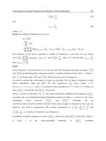
The broad range of physical properties available in metal-oxide materials is now beginning
to be exploited in the form of epitaxial functional oxide thin-film heterostructures for the
purposes of modern nanoelectronics. The discovery of high-T
c
superconductors and
requirements for their structural perfection and chemical homogeneity also stimulated the
rapid development of deposition and patterning technologies for thin films of conducting,
insulating, ferroelectric, ferromagnetic and also multiferroic oxide materials. For example,
epitaxial heterostructures with SrTiO
3
(STO) display high-mobility of charge carriers, two-
dimensional interface conductivity, field-induced superconductivity, and the thermoelectric
effect (see, e.g., Ohtomo & Hwang, 2004; Jia et al., 2009). The multifunctional metal-oxide
heterostructures help to keep pace in shrinking dimensions down to the nanometer-scale
and the increasing complexity of integrated electronic circuits, which are among the most
distinctive features of modern times. Rapid progress in general purpose applications of the
metal-oxide heterostructures has, in turn, supported further development of high-T
c
superconducting devices. Up to now, the most advanced high-T
c
superconducting epitaxial
oxide thin-film heterostructures include thin films of YBa
2
Cu
3
O
7-x
(YBCO) superconductor
and the technologically compatible with it metal-oxide materials whose crystal structures
are mainly derived from perovskite-type crystal structures. All-oxide heterostructures based
on high-quality epitaxial YBCO thin films with other metal-oxide layers are indispensable
for high-T
c
superconducting quantum interference devices (SQUIDs) with the highest
possible magnetic field sensitivity at 77 K.
SQUIDs are used for ultrasensitive electric and magnetic measurements of all physical
quantities that can be converted into magnetic flux, for example, magnetic field, magnetic
field gradients, current, voltage, displacement, magnetic susceptibility etc. SQUIDs serve as
extremely sensitive magnetic field sensors for biomagnetic measurements, geomagnetic
survey, non-destructive evaluation, low-noise preamplifiers, picovoltmeters, etc. (see, e.g.,
Kleiner et al., 2004; Clarke & Braginski, 2006; Fagaly, 2006). It is important that the SQUID
magnetometers measure vector components of magnetic fields. In addition, they can
measure (in hardware!) spatial gradients of magnetic fields; they are able to resolve tiny
changes (~1 fT) in large (~ 1 µT) signals, and have a white noise spectrum in a wide
frequency range (1 Hz – 10 MHz). No other magnetic field sensor has this combination of
properties, which are especially important for, e.g., biomagnetic applications. Biomagnetic
Applications of High-Tc Superconductivity
148
applications demand a very challenging tasks of measurements of tiny magnetic fields
generated by very weak ionic currents in biological neural networks and the real time
inverse calculations for the localization of these ionic currents.
High-T
c
superconductors have significant potential for further developments in fundamental
physics and applications (Faley, 2010c). Increased interest in the high-T
c
superconducting
devices is spurred by the expected up to 30-fold price increase for liquid helium due to a
drastic shortage of reserves (Witchalls, 2010). This will impact, first of all, the biomagnetic
applications of low-T
c
DC SQUIDs, for example, for magnetoencephalography (MEG), where
the implementation of cryocoolers can ruin the sensitivity of measurement systems. The high-
T
c
SQUIDs demonstrate low noise properties up to the temperatures of about 80 K, which can
be easily reached with cheap liquid nitrogen. Most of the presently available high-T
c
SQUIDs
are optimized for operation at a temperature 77 K, at which the equilibrium vapour pressure
of liquid nitrogen coincides with atmospheric pressure. Replacement of low-T
c
SQUIDs with
high-T
c
SQUIDs in future MEG systems would make the MEG systems independent of helium
supplies, much more user-friendly, and would save up to about €100,000 per year in
operating costs per multichannel MEG system thus stimulating general acceptance of the MEG
systems for clinical use. Liquid nitrogen is about ten times cheaper than liquid
4
He and can be
easily obtained from air. It is also sufficient to replenish the liquid nitrogen in standard
cryostats for MEG only about once a month and this can be done simply through a long non-
magnetic silicone tube from a stationary tank placed outside the magnetically shielded room.
The optional cycle refrigeration recondensing the cryogen between measurements would be
also much cheaper and simpler in the case of the high-T
c
MEG system compared to the low-T
c
system. Also in the case of measurements of the currents of high-energy heavy-ion beams in
the radioisotope beam accelerators, the implementation of high-T
c
SQUID systems can save
operating costs of about $150,000 per year for each system compared to the low-T
c
SQUID
systems (Watanabe et al., 2010).
An important prerequisite for the application of high-T
c
SQUIDs for MEG systems is
magnetic field resolution better than 10 fT/√Hz down to frequencies of few Hz at 77 K. Such
sensitivity of high-T
c
SQUIDs has been achieved by a number of groups using
superconducting multilayer flux transformers with a multiturn input coil for optimal
coupling of the magnetic field to be measured to the high-T
c
DC SQUID loop (Dantsker et
al., 1995) (Drung et al., 1996) (Faley et al., 2001, 2006b). Reduction of the excess low
frequency noise of the multilayer high-T
c
DC SQUID magnetometers is crucial for
applications. This can be achieved only with the highest degree of crystalline perfection and
stoichiometry of the high-T
c
superconducting thin films in the multilayer heterostructures.
The choice of the proper deposition method and deposition conditions as well as the
technologically compatible materials for substrates and oxide heterostructures is important
for providing the best possible epitaxial growth of all films involved (Faley et al., 2006b).
Influences of lattice mismatch and difference in thermal expansion coefficients of the
materials in the epitaxial oxide heterostructures should be minimized because they lead to
strains inside the high-T
c
superconducting films and deteriorate their properties (Faley et al.,
2006a). Patterning techniques as well as proper layouts and capsulations are also essential
for the total sensitivity of the high-T
c
DC SQUID sensors to be optimised for particular
applications.
In this chapter the technological aspects and physical properties of epitaxial oxide
heterostructures are described, which are used for the preparation of high-T
c
DC SQUID