Designing and Deploying RFID Applications Part 10 doc
Bạn đang xem bản rút gọn của tài liệu. Xem và tải ngay bản đầy đủ của tài liệu tại đây (1.88 MB, 30 trang )
An RFID-Based Anti-Counterfeiting Track and Trace Solution
257
Vortex86SC by a DDR2 interface, and a graphical controller XGI Volari Z9s connected
to Vortex86SX by a PCI interface. After defining these requirements, printed circuit
board (PCB) design can be started. Electrical circuitries can be performed for MICC02
version (with VGA port), and the MICC01 (without VGA) can be obtained by using the
same PCB, on which the graphical controller and DDR2 memory used will not be
mounted.
The MICC module is designed according to Vortex86SX (***a, 2010) produced by DMP
company (***b, 2010). Vortex86SX is a SoC x86, manufactured by using 0.13 microns
technology and a model of very low power consumption (less than 1 Watt). This intelligent
SoC displays important features, such as: various interfaces of input/output (RS-232,
parallel, USB or GPIO), BIOS, WatchDog type timer, management of power consumption,
MTFB counter, LoC (LAN on chip), JTAG, etc., features that are not integrated on a single
chip of 27x27mm (BGA-581). Vortex86SX is compatible with Windows CE, Linux and DOS
operating systems. It integrates, on the same chip SoC 32KB a cache memory L1, ISA bus on
16bits, PCI bus Rev. 2.1 of 33MHz on 32 bits, SDRAM, DDR2, ROM controller, IPC
(peripheral internal controllers with DMA and timer/counter of interruption included), SPI
(serial peripheral interface), Fast Ethernet MAC, FIFO UART, USB 2.0 main and IDE
controller.
5. Designing PCB circuit board for MICC module
The next step in designing the MICC module is the PCB circuit board design. We aimed to
obtain a board of 11x11cm, resulting in an ergonomic MICC module of low sizes. The PCB
circuit board is structured on 3 layers (Top, Middle and Bottom) of minimal width of a
running wire of 10 mil (use of three layers is preferred, due to the high number of pins for
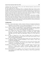
Vortex86SX SoC chip). Fig. 4 illustrates the PCB circuit board for designing the MICC
device.
¶(
9)
Fig. 4. Front and back images of the PCB
6. Software architecture of the ATPROD system
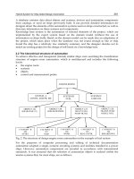
The general architecture of the ATPROD system is illustrated in Fig. 5. It is obvious that
several manufacturers may co-exist in this architecture. Each of them could have more
production lines, geographically distributed in more locations. The warehouses and retailers
are also geographically distributed in some more locations, provided with Internet
connection, in order to have access to the manufacturers’ servers and to be able to
authenticate products and send information related to their traceability.
Designing and Deploying RFID Applications
258
Fig. 5. Software architecture of the ATPROD system
Each manufacturer has a central server, on which an OPC_UA_HDA_AT server runs. This
server will store information regarding the products that exit the production line and are
sent to the resellers’ warehouses. At the level of each distribution point, there is a PC that
runs an OPC_UA_AT server. This server is able to send requests for information about the
manufacturing process, as well as to save relevant information within a local database
historian.
It is important to remember that this server should not be in the same location as the
manufacturing points, where the only condition to be met is the existence of an Internet
connection. In this way, OPC_UA_AT servers from the manufacturing points are in fact
clients of the OPC_UA_HDA_AT server. Fig. 5 also illustrates the way in which the shared
database is developed: for each reseller, the database is shared to all distribution points and
central server.
Each warehouse is provided with a server, on which an OPC_UA_AT server runs; this
server also represents a client of OPC_UA_HDA_AT associated to each producer, in order
An RFID-Based Anti-Counterfeiting Track and Trace Solution
259
to require necessary data for authentication. The manufacturer’s server will also receive
information about input of products, storing conditions or exit of products
from warehouses. In what concerns the retail dealers, a PDA with an RFID reader can be
used, on which a client of OPC_UA_HDA_AT servers runs. These servers are clients
for OPC_UA_AT manufacturers’ servers and can be used in order to authenticate
products.
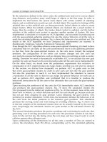
Fig. 6. ATPROD system seen from the perspective of a retail dealer
Designing and Deploying RFID Applications
260
A client from a warehouse or retail dealer can send an authentication request to the
manufacturer’s servers (central or local). If the needed information cannot be found within
the central database server associated to the manufacturer, this will require data from a
server existing in the manufacturing point. After information is achieved, it is sent to the
client which has required it, in order for the client to identify products. Using such
mechanism, information existing within the shared database related to the tagged products
can be freely accessed.
As can be seen in Fig. 5, the shared database between manufacturers’ local servers and the
central servers is illustrated in red color. For each point, a SQL database server is set up.
OPC_UA_AT and OPC_UA_HDA_AT servers can access the local database by means of
SQL commands.
Fig. 6 emphasizes the way a shared database can be accessed by dealers. Therefore, one or
several PDA or tag-reading PCs can be provided for each dealer. It is very important that
PDA devices and PCs used for authentication should be connected to the Internet, so as to
make possible the access to the manufacturers’ servers. If the Internet connection of a
manufacturer associated server does not work properly, the authentication of products will
not be accomplished. On such computing systems, an OPC client application runs for
OPC_UA_HDA_AT servers associated to each manufacturer. When a product is sold, the
client application requires information from the manufacturer’s server in relation to the
authentication of that product.
The requested information is sent to client application, and the authentication of product is
carried out. After authentication, information concerning the selling of product is sent back
to the manufacturer’s server.
Information concerning the selling of products is not erased from the database. By means of
client application, the database administrator will be able to carry out erasing operations
related to products sold or to create an archive with this information (for each
manufacturer) that users can use at a later time.
Operationally, servers within ATPROD system are placed in two different locations: at
manufacturers and in warehouses. Fig. 7 illustrates the structure of servers, as seen from the
manufacturer’s perspective.
There are several RFID tagging points at each manufacturing point, and several MICC
modules connected to RFID readers. The OPC servers running at these points are assigned
as OPC_DA_CE_AT and their presence is justified by the necessity to label all products
that exit the production line. Since MICC module should work both online and offline, a
historian OPC server can also run on it; therefore, a historian will be carried out for data
that should have been sent on network, but cannot be transmitted when the connection
with the server is no longer active at the level of manufacturing points. OPC_UA_AT
server existing at the manufacturing point level includes OPC_DA_UA_AT and
OPC_HDA_UA_AT wrapper, so as to connect to OPC_DA_AT and OPC_HDA_AT
servers on MICC modules. This server stores a historian with all operations performed at
the manufacturing point. The central server OPC_UA_HDA_AT from the manufacturer’s
level should also be a client of the OPC_UA_AT servers, at the level of manufacturing
points, so as to require the necessary data. However, such data is not stored within the
central server database, but within the database of manufacturing points. OPC_UA_AT
servers can be replaced with OPC_NET3.0_AT servers that use WCF (Windows
Communication Foundation) technology.
An RFID-Based Anti-Counterfeiting Track and Trace Solution
261
Fig. 7. Placing of servers to the manufacturer site
Designing and Deploying RFID Applications
262
Fig. 8. Placing of servers to warehouses’ site
Fig. 8 emphasizes the architecture of servers as regards the warehouses. One might see that
here, at the level of each system’s gate, there is a MICC module. Such a module is provided
with an RFID reader, connected by RS232 serial port or USB port, in order to read/write
information from RFID labels. This module runs OPC_DA_CE_AT and OPC_HDA_CE_AT
servers. An OPC_UA_AT server runs on a server at the warehouse level. This server is a
client of OPC_DA_CE_AT and OPC_HDA_CE_AT from MICC modules. This fact is
accomplished by including the OPC_DA_UA_AT and OPC_HDA_UA_AT wrappers. In
order to achieve the information necessary to product authentication, this server signifies a
client of the servers existing at manufacturers’ level. Any input or output of products from
An RFID-Based Anti-Counterfeiting Track and Trace Solution
263
the warehouse will be sent to manufacturers’ servers. In case of small distribution chains,
OPC_UA servers can be replaced with OPC_NET3.0_AT servers that use the WCF
(Windows Communication Foundation) technology.
Up to the present, six types of servers have been identified: OPC_DA_CE_AT,
OPC_HDA_CE_AT, OPC_UA_AT, OPC_DA_UA_AT, OPC_UA_HDA_AT,
OPC_NET3.0_AT.
OPC_DA_CE_AT runs on MICC modules, specific to manufactures and warehouses. This
server includes a driver for the communication with RFID reader. Such a server should run
on WINDOWS CE 6.0 operating system. OPC_HDA_CE_AT runs on MICC modules,
specific to manufacturers and warehouses. This server is a client of OPC_DA_CE_AT server
and will carry out a history if the local connection is interrupted. The server should run on
WINDOWS CE 6.0 operating system. OPC_UA_AT runs at the level of manufacturing
points and warehouses. It is a client of OPC_DA_CE_AT and OPC_HDA_CE_AT servers,
including the OPC_DA_UA_AT and OPC_DA_UA_AT wrappers. This is also a client of
OPC_UA_HDA_AT servers, at the level of manufacturers. OPC_UA_HDA_AT runs at the
level of manufacturing points and centralizes all data corresponding to products circulating
within the distribution chain. OPC_NET3.0_AT- emphasizes an alternative of OPC_UA_AT
and OPC_UA_HDA_AT servers.
7. Software architecture of the MICC module
MICC module is connected by means of RS232 or USB ports to a RFID reader/writer, using
13.56 MHz frequency band and ISO 15693 standard. This module should allow the reading
or writing of information on RFID tags.
One should mention that products can use two types of RFID tags: standard self-adhesive
RFID tags, 13.56 frequency band, ISO 15693, variable memory (I code SLI – 896 bits, Tag-it
TM HF-I - 2048 bits) and RFID tags of types: flexible card, self-adhesive, active, 13.56 MHz
frequency band, ISO 15693, provided with integrated temperature sensor and temperature
values history, Variosens model made by KSW Microtec, 8kbits EEPROM, which can store 1
720 values of 10 bits temperature values. All products have tags attached to them, mostly of
them of first class mentioned above; those products that need special conditions of
warehousing and transport can also have attached RFID tags of the second type.
Operationally, the MICC device should meet the following requirements: reading of
information from RFID tags; setting up the tags so as to establish the sampling rate; if
necessary, reading the temperature and storing its value into RFID tag’s memory; storing of
information read from RFID tag into its own memory; sending data to central server by
means of Ethernet; possibility of both on-line and off-line operations.
Fig. 9 illustrates the position of MICC module within ATPROD system. Therefore, it is
placed at the input or exit of a warehouse. In what concerns the input, the MICC device
reads the RFID tags attached to products that enter warehouses, sends the information read
to the central server, accomplishes the authentication of products (by comparing
information from tags to information existing within manufacturer’s server), and writes the
information related to the input on RFID tag. When products have attached RFID tags
provided with temperature sensors, the MICC module reads the history of temperatures
and deletes this history from RFID tag.
Designing and Deploying RFID Applications
264
¶(9
pt)
Fig. 9. MICC module operating mode
Fig. 10 also shows the UML diagram with a view to using the MICC module. From this
diagram, the main two operations carried out in this module can be identified, as follows:
reading of information from RFID tag, as well as writing of information on this RFID tag.
Fig. 10. UML diagram of using MICC module
An RFID-Based Anti-Counterfeiting Track and Trace Solution
265
Reading of information from RFID tag is done depending upon RFID tag’s type (with or
without temperature sensor). The operation of product authentication is carried out after
reading information from RFID tag, and includes the connection to the manufacturer’s
server, the reading of information from this server about products, and finally a comparison
between this information and that provided on RFID tags. Due to this procedure,
authentication of products can be performed only if the module is provided with direct
connection to manufacturers’ servers.
As previously stated, data writing is performed depending upon the RFID tag under use. If
an RFID tag provided with temperature sensor is used, then the sampling rate can be set up
in order to save temperature values, and to empty the memory after reading the information
included on RFID tag. If a classical tag is used, that is, without temperature sensor, then the
tag will be written with information concerning the input or exit in or from warehouse,
input/exit date, warehouse code, etc.
The application running on MICC device will be further developed in C++, under an OPC
server type, able to communicate with the RFID by means of RS232 or USB. The application
will be developed by using SDK package, performed after creating an image on Windows
CE 6.0 (Samuel, 2008).
8. Conclusion
RFID will have significant impacts on the economy as well as on the operational and
financial performance of companies in the focus areas: productivity, employment, markets,
goods and services, and innovations and new products. RFID will especially generate
significant impacts in applications with a unique selling proposition, e.g. anti-counterfeiting,
secure supply chains, and cold chain and quality monitoring, as well as better information
for decision makers.
This chapter proposes an RFID-based system to track, at the item level, material flows
among partners until they reach the consumer, while maintaining data accuracy. The
presented system helps small, medium companies and enterprise organizations to improve
productivity and provide better service to their customers. Thus, our system has the
potential of helping retailers provide the right product at the right place at the right time,
allowing maximizing sales and profits.
The system is still under construction and in the near future some security aspects will also
be taken into consideration.
9. Acknowledgment
This work was supported by the project "Computer system for controlling and checking the
authenticity of products - ATPROD" - Contract no. 12082/2008, project co-funded by 2007-
2013 PNCDI Program.
10. References
Barr, M., (2007). Embedded Systems Glossary, Available at
Chalasani, S.; Boppana, R.V.; Sounderpandian, J. (2005). RFID Tag Reader Designs for Retail
Store Applications, AMCIS 2005 Proceedings, Paper 149, Available at
Designing and Deploying RFID Applications
266
Gaitan, N. C.; Gaitan, V. G.; Pentiuc, S. G.; Ungurean, I.; Dodiu, E. (2010). Middleware based
model of heterogeneous systems for scada distributed applications, Advances in
Electrical and Computer Engineering. Vol.10, No.2, pp. 121-124, ISSN: 1582-7445
Lange, J.; Iwanitz F.;, Burke, T.J. (2010). OPC - From Data Access to Unified Architecture, fourth
edition, revised and extended, 431 pages, ISBN 978-3-8007-3242-5
Mahnke, W.; Leitner, S.H.; Damm, M. (2009). OPC Unified Architecture, Springer; 1 edition
(May 4, 2009), ISBN: 978-3-540-68898-3
Preradovic, S.; Karmakar, N.C.; Balbin I. (2008). RFID Transponders, IEEE MICROWAVE
MAGAZINE, Vol. 9, No. 5, pp. 90-103, ISSN: 1527-3342
Samuel P.(2008). Professional Microsoft Windows Embedded CE 6.0, Wrox; New edition
(November 3, 2008), ISBN: 978-0470377338 ***a (2008). A Summary of RFID
Standards, RFID Journal, Available at:
***a (2010). Vortex86
System-On-Chip (SoC), Available at ***b (2010). DMP
Electronics INC., Available at
16
A Knowledge-Based Approach for
Detecting Misuses in RFID Systems
Gennaro Della Vecchia
1
and Massimo Esposito
1,2
1
Institute for High Performance Computing and
Networking of the National Research Council of Italy
2
University Parthenope
Italy
1. Introduction
In the last few years, the Radio Frequency IDentification (RFID) technology has gained
increasing attention as an emerging solution for automatically identifying remote objects,
people, animals. Early successful applications in asset tracking and supply-chain
management and the falling cost of RFID tags have fostered a broadening of the application
domain, with new pervasive, RFID-based solutions supporting more user-oriented services.
As a result, RFID technology is going to contribute to the massive deployment of sensors in
an ever more networked society –a coming Internet of Things where everything is alive, that
is, where common objects (including those that are inanimate and abstract) can have
individual identities, memory, processing capabilities, along with the ability to
communicate and sense, monitor and control their own behavior (Thompson, 2004). In
previous works we have explored this technology’s potential to facilitate everyday life by
seamlessly integrating virtual and physical worlds, varying from personnel tracking and
localization to healthcare monitoring (Ciampi et al., 2006; Coronato et al., 2009; Della
Vecchia & Esposito, 2010; Esposito et al., 2009; Coronato et al., 2006).
As known, typical RFID systems use a combination of tags, readers and middleware as
sketched in Fig. 1. Basically, a reader broadcasts a radio frequency signal to get the data
stored on the nearby tags. Data can be a static identification number, user written data or
data computed by the tag itself. Having obtained tag data, the reader informs via a wired
or wireless network the middleware that in turn stores both tag and reader data in a back-
end database.
RFID systems deal with information which very often, if not always, may be critical. Such
systems are intrinsically insecure and vulnerable, being prone to threats that can affect tag,
reader and middleware as well .
In particular, tag cloning is one of the most serious threats to the security of RFID systems.
Tag cloning simply consists in catching a tag’s unique identifier with the aim of making an
exact copy (clone) of the cloned tag, so that the clone can pose as the genuine tag, being
indistinguishable from the original. Once legitimate tag data are obtained, attackers can
reproduce their clone tags on a wide scale and gain access to secured facilities, make
fraudulent purchases, alter or even disrupt supply chains, etc.
One conventional approach to secure RFID systems against tag cloning might use
cryptographic tags that enable strong tag authentication and make tag cloning a rather
Designing and Deploying RFID Applications
268
daunting task, but this would skyrocket the cost of the single tag. As a result, a viable
solution to defend against tag cloning in RFID systems seems yet to be developed due to the
RFID industry’s desire to manufacture commercially affordable tags.
Tags
Reader
Reader
RFID Middleware
Network
DataBase
Fig. 1. A typical RFID System Architecture
A less conventional approach to address the tag cloning issue may exploit the well-known
security paradigm of “intrusion detection”. Generally speaking, an intrusion detection
system monitors a given environment and implements a detection method to reveal
suspicious activities and respond accordingly. One diffused intrusion detection method is
“misuse detection”, which utilizes a knowledge base that explicitly models the concept of
what is deemed to be “suspicious”. Everything that does not match the expected behavior
formalized in the knowledge base is considered to be “normal”.
In this book’s chapter we propose a methodology in which misuse detection uses a
knowledge base built upon a “track & trace” model relying on the notion of “tag location” to
gather all the information required to identify an attack of tag cloning. The knowledge base
embedding the track & trace model is formalized in an ontology by means of semantic web
languages in order to achieve an unambiguous, well-defined and machine-readable
knowledge representation.
The methodology here described stands on three key points: i) the definition of an ontology
model formalizing expected and actual profiles, each of them being based on location and
tracking information about RFID tagged objects; ii) the application of an inferential engine
that, exploiting inference patterns proper to the logic underlying the ontology formalism,
checks the consistency between expected and actual profiles of tagged objects; iii) the
detection and identification of anomalous conditions in presence of inconsistencies. This
methodology led to the design of a misuse detection system aimed at detecting and
characterizing tag cloning in RFID applications. Such a system exhibits a reactive and event-
dependent behavior in response to new tracking information coming from a network of
RFID systems and shows an architecture structured in a set of components operating at
middleware layer that can be transparently integrated into existing RFID applications.
The rest of the chapter is organized as follows. Section 2 introduces some preliminary
notions, Section 3 discusses motivations and related work, Section 4 describes the proposed
methodology and Section 5 illustrates the MDS architecture along with a proof of concept of
the knowledge-based approach. Finally, some concluding remarks are reported in Section 6.
A Knowledge-Based Approach for Detecting Misuses in RFID Systems
269
2. Preliminaries
2.1 Intrusion detection taxonomy
Intrusion Detection Systems (IDS) can be classified in several ways. It is common to classify
an IDS according to the detection method, the audit source, the usage frequency and the
response mechanism (Debar et al., 1999).
Classification by the detection method is the most diffused. Mainly, two kinds of detection
methods are considered: misuse detection and anomaly detection.
Misuse detection systems utilize a knowledge base that explicitly models what is not
allowed. Everything that does not match the knowledge base is allowed.
Anomaly-based systems, on the contrary, use a model of normal activity and anything that
does not match the model of normality is considered an attack. An anomaly detector
assumes that all anomalous events are signs of an attack and that all attacks produce
anomalous events. Since an anomaly-based system does not model attacks specifically, it
can detect previously unknown attacks.
Misuse-based systems, on the other hand, can detect attacks of which they have prior
knowledge, being unable to detect new forms of attack but some mutation of those already
in the rule base. However, a misuse detection approach paves the way to a clear
understanding of the application domain, where users need to be aware of and formalize
their knowledge about specific misuse scenarios. This leads to low false positive rates and
permits a simple and efficient processing of the audit data.
A different method of classification of IDSs takes into account the type of audit data
processed. Three different categories of audit data are common, namely network-based
audit data, host-based audit data and application-based audit data.
Network-based sensors collect packets from the protected network in order to perform
detection. Some network-based systems use firewall logs as input. These firewall logs
contain the headers of the network packets that have been blocked by the firewall. Host-
based sensors process audit data generated by a host's operating system. It is very common
for this type of sensor to perform detection on the log of system calls that have been
executed (Hofmeyr et al., 1998; Kruegel & Robertson, 2004). Application-based sensors
process logs created by a user-space application. This kind of sensor is usually used to
protect network demons, as several systems exist that process web logs.
IDSs systems can also be classified according to their usage frequency. Online systems
operate in real-time and consume audit data as they are generated. This is the most common
mode of operation. Other systems are run in offline mode, where the system is activated
periodically to look for signs of attack.
Finally, it is also possible to classify Intrusion Detection Systems according to the type of
response the system yields when an attack is detected. The most common is passive
response, where an attack occurrence is logged or the administrator is alerted by other
means (e.g., SMS or email). Active response systems block an incoming attack so that it
cannot succeed. They are usually referred to as Intrusion Prevention Systems. Depending on
the implementation, an active system could, for instance, send a reset packet to tear down
the attacker's connection or update the firewall rules so that the attacker is blocked.
2.2 Ontology modeling
Historically, Ontology is the philosophical study of the nature of being, existence or reality as
such, as well as the basic categories of being and their relations. Traditionally listed as a part of
Designing and Deploying RFID Applications
270
the major branch of philosophy known as metaphysics, Ontology deals with questions
concerning what entities exist or can be said to exist, and how such entities can be grouped,
related within a hierarchy, and subdivided according to similarities and differences. By
extension, the core meaning of “ontology” within Computer Science is a model for describing
the world that consists of a set of types, properties, and relationship types. What ontology has
in common in both computer science and philosophy is the representation of entities, ideas,
and events, along with their properties and relations, according to a system of categories.
The term “ontology” is currently used to mean “a formal, explicit specification of a shared
conceptualization” (Gruber, 1995). In this perspective, “conceptualization” relates to an
abstract model that identifies the relevant concepts of a certain domain. “Explicit” means
that the type of concepts used and the constraints on their use are explicitly defined.
“Formal” means that the ontology should be formalized to be machine understandable and
enable intelligent agents to infer new statements from existing ones based on a set of rules.
“Shared” means that an ontology captures consensual knowledge of a community. Simply
put, ontology refers to a formalization of knowledge in a given domain.
An ontology can be used to explicitly represent the meaning of terms in vocabularies and
the relationships between those terms. In other words, ontology is the concept which is
separately identified by domain users, and used in a self-contained way to communicate
information. In particular, some of the reasons why someone wants to develop an ontology
are to share common understanding of the structure of information among people or
software agents, to analyze domain knowledge and enable its reuse, to make domain
assumptions explicit, to separate domain knowledge from the operational knowledge.
An ontology structure holds definitions of concepts, binary relationships between concepts
and attributes. Three types of relationship may be used between concepts: generalization,
association, and aggregation. Relationships may be symmetric, transitive and have an
inverse. Concepts, relationship types and attributes and rules, put together, enable the
description of a schema in terms of abstraction. On the other hand, concrete objects populate
the concepts, concrete values instantiate the attributes of these objects and concrete
relationships instantiate relationships.
The semantic web languages used to formalize an ontology are defined with a model-
theoretic semantics. In particular, for the language OWL (Web Ontology Language) (Patel-
Schneider et al. 2004), a semantics was defined so that very large fragments of the language
can be directly expressed using so-called description logics (Baader et al., 2005). Description
logics are a decidable subset of first order predicate logic. Namely, OWL DL (where DL
stands for "Description Logic") was designed to support the existing description logic
business segment and provide a language subset that has desirable computational
properties for reasoning systems.
DL-based knowledge bases are built using concept language expressions, and they are
usually divided in two distinct parts: intensional and extensional. The intensional part takes
the name of T-Box and describes the general conceptual domain model made of concepts
and relationships between concepts and attributes, whereas the extensional part is named
A-Box and constitutes a (partial) instantiation of the model, since it contains assertions about
a set of individuals.
2.3 Ontology reasoning
The effective use of ontology modeling in real applications is critically dependent on the
provision of efficient reasoning services to support both ontology design and deployment. In
A Knowledge-Based Approach for Detecting Misuses in RFID Systems
271
such a direction, DL-based ontologies have stretched the capabilities of DL inference
engines, offering a collection of reasoning services implemented through automated
reasoning techniques.
The reasoning services provided by a DL inference engine can be classified as basic services,
which involve the checking of the truth value for an assertion, and complex services (Donini
et al., 1996). Generally speaking, basic services are, for instance, the verification of the
subsumption between two concepts or the satisfiability of a concept, whereas complex
services implement tasks such as finding all the individuals being in a concept expression,
or organizing in form of taxonomy the concept names appearing in a terminology. In more
detail, basic services can be classified in services of terminological reasoning and hybrid
reasoning, respectively. Terminological reasoning involves only the terminology (i.e.
without considering A-Box assertions), whereas hybrid reasoning takes account of both the
parts of a knowledge base, i.e., T-Box and A-Box.
On one hand, terminological reasoning services are intended to verify both Concept
Satisfiability and Subsumption, i.e., to check whether a newly defined concept makes sense or
is contradictory with respect to the existing T-Box, and to check if a concept C is more
general than another concept D, respectively. On the other hand, hybrid reasoning services
are aimed at verifying A-Box Consistency (with respect to the T-Box) and executing Instance
Checking. Specifically, A-Box Consistency checks whether a new assertion in the A-Box
generates an inconsistency with reference to the T-Box, whereas Instance Checking allow to
decide whether an individual is an instance of a concept or not.
The provided complex reasoning tasks vary from system to system, and are defined on top
of the basic services above described. The most common are Classification and Retrieval,
which are terminological and hybrid reasoning services, respectively. Classification consists
of explicitly representing the concept taxonomy entailed by the knowledge base, being this
taxonomy a graph whose nodes are the concept names appearing in the knowledge base,
and the edges represent the subsumption relation between them. This graph can be built by
checking the subsumption between every pair of concept names. Retrieval (or Query
Answering) consists in collecting all the individuals in the knowledge base that are instance
of a given concept in every model of the knowledge base.
3. Motivations and related work
3.1 Motivations
The most challenging security threat in RFID applications is tag cloning. The conventional
approach to secure RFID systems against tag cloning is to use cryptographic tags that enable
tag authentication and make tag cloning considerable harder. The fundamental difficulties
of such an approach revolve around the trade-off between tag cost, level of security, and
hardware functionalities. As a matter of fact, RFID tags are typically deployed in great
amount and the end-user companies have a strong financial incentive to minimize the tag
cost and, thus, the features the tags provide (Lehtonen et al., 2009).
As a result, it is extremely difficult to use cryptography for protecting low cost tags from
cloning, due to their limited power, storage and processing resources. Moreover, in order to
supply cryptographic components with sufficient power, tags would need to be read from a
shorter distance, which would degrade the read-rate of readers (Ranasinghe et al., 2005).
A less conventional approach makes use of location information to detect RFID clone tags.
Location-based product authentication is an anti-counterfeiting measure that brand-owners
Designing and Deploying RFID Applications
272
may use in many situations to fight against product forgery. For instance, in the last years
the pharmaceutical industry has been planning to track and trace the history of each single
medicine using RFID information as an effective and proactive measure against cloning,
instead of using expensive cryptographic tags. Obviously, the goal of this approach is not to
make tag cloning harder. Rather, by properly detecting the presence of clone tags and acting
accordingly, it aims at nullifying their effects: a tagged product that lacks valid track and
trace history can be easily singled out and labeled as not genuine, thus posing a substantial
barrier against counterfeit players.
Keeping in mind the aforementioned trade-off between cost and effectiveness, there are at
least a couple of good reasons to assume that the location-based approach can be suitably
followed when it comes to fight tag cloning. First, efforts focused on the tag itself are
intrinsically insecure, because in an RFID system tags constitute the weakest link in the
whole chain due to their limited functional capabilities: an attacker, even with poor
resources, can violate their security quite easily; on the other hand, it is rather questionable
whether it will be ever possible to produce a truly secure RFID tag, able to address all
known vulnerabilities without increasing the overall cost. As a second but not secondary
consideration, even if some solution may prove itself effective on preventing tag cloning, a
really secure RFID system should go beyond prevention measures and provide detection
capabilities when tag cloning has already occurred (Mirowski & Hartnett, 2007).
All these considerations constitute the rationale which led us to adopt the location-based
approach in developing the methodology proposed in this chapter.
3.2 Related work
RFID technology raises a number of security and privacy concerns, which may substantially
limit its deployment and reduce potential benefits. Among the great deal of papers
addressing these concerns, an interesting survey can be found in (Rotter, 2009), with the
focus put on the technical aspects of security and privacy.
Most specific literature covers the topic of tag cloning and the efforts made by the research
community to tackle this threat through a wide range of solutions.
In costly RFID tags, where resources are less subject to strict constraints, several
countermeasures have been devised to combat tag cloning, such as deactivation of tags,
encryption, authentication and hash codes (Karygiannis et al., 2007). In (Juels, 2005), some
techniques are illustrated for strengthening the resistance of EPC tags against cloning
attacks, using PIN-based access to achieve challenge response authentication. In (Weis et al.,
2004), the authors proposed a cryptographic approach to lock the tag without storing the
access key, but only a hash of the key on the tag instead. The key is stored in a back-end
server and can be found using the tag’s meta-ID.
Duc et al. (Duc et al., 2006) proposed a communication scheme to protect user privacy in
RFID system which is based on a synchronous session key between tags and back-end
database server to authenticate each other. A further development of Duc’s scheme which
overcomes some vulnerabilities has been proposed in (Cheng et al., 2009).
Avoine and Oechslin (Avoine & Oechslin, 2005) proposed another hash-based RFID protocol
providing modified identifiers for improving privacy that can be applied for authentication.
In addition, hash-based RFID protocols for mutual authentication have been proposed in
(Choi et al., 2005; Lee et al., 2006). All these protocols rely on synchronized secrets residing on
the tag and back-end server and require a one-way hash function from the tag.
A Knowledge-Based Approach for Detecting Misuses in RFID Systems
273
In contrast, in low cost RFID passive tags, due to their small size and strictly constrained
resources, complex cryptographic solutions like hash functions cannot be implemented. In
(Sarma et al., 2003) the authors mention scarcity of tag resources in low-cost RFID systems
as a primary challenge in providing security and privacy mechanisms, and in combating
cloning as well. In this perspective, few lightweight authentication protocols that do not
require cryptographic hash/keys in the tag have been proposed (Karthikeyan & Nesterenko,
2005; Chien, 2007). Yet another approach to tackle tag cloning uses a Physical Unclonable
Function (PUF) (Devadas et al., 2008). PUFs significantly increase physical security by
generating volatile secrets that only exist in a digital form when a chip is powered on and
running. Its main property is that it is easy to generate but hard to characterize.
As it clearly appears, all these efforts aim at preventing tag cloning. However, detecting fake
tags plays a not lesser role. Once genuine tags have been cloned, the success of a potential
attack greatly depends on the capabilities of the whole system to timely recognize it and
react accordingly.
Clone detection can be achieved through the gathering of information at the middleware
layer. For instance, a very interesting approach has been proposed in (Mirowski & Hartnett,
2007, ib.). The authors have proposed an intrusion detection system for RFID systems, called
Deckard, based on a statistical classifier and oriented to the detection of change of tag
ownership. This is one of the early researches devoted to the need of intrusion detection
systems in RFID. Another remarkable approach, similar to Deckard’s intrusion detection
architecture, has been proposed in (Thamilarasu & Sridhar, 2008). Its concern goes beyond
the change in tag ownership and provides a more generic security framework to detect a
variety of RFID malicious attacks.
The methodology we are going to describe in this chapter shares with these latter works the
basic concept of applying intrusion detection techniques to identify tag cloning. But,
differently, our research efforts have been primarily focused on integrating the principles of
ontology modeling and reasoning in the intrusion detection paradigm.
Until recently, few literature can be found about the adoption of the ontology-based
approach in developing IDSs. In particular, Raskin et al. (Raskin et al., 2001) advocated the
use of ontology modeling in the field of information security in order to provide a common
ontology that lets IDS sensors agree on what they observe. Undercoffer et al. (Undercoffer et
al., 2003) proposed a target centric ontology for intrusion detection that models properties
that are observable and measurable by the target of an attack. Li et al. (Li et al, 2008)
described a hierarchical knowledge model to support alert correlation, formalized in an
ontology and a set of rules built on top of it. However, to the best of our knowledge, the
RFID security literature has not yet addressed applications of inferential engines and
ontology modeling to implement intrusion detection techniques in RFID systems, neither
system-oriented researches appear to have been developed in that direction.
4. Misuse detection system methodology
4.1 Track and trace model
The Misuse Detection System (MDS) described in this chapter belongs to the class of IDS
characterized by misuse detection as detection method, application-based sensors as type of
audit data processed (i.e., the RFID readers), real-time as usage frequency (i.e., audit data
are processed as they are generated) and passive response (i.e., an attack occurrence is
logged and the administrator is notified of it) (see Sect. 2.1).
Designing and Deploying RFID Applications
274
The methodology devised to design the MDS relies on a knowledge base containing a “track
& trace” model that formalizes all the information required to identify an attack of tag
cloning. Such a model essentially relies on the reasoning that when you know where the
genuine tagged object is, the fake/clone ones can be detected.
More in detail, the model includes static and dynamic profiles to be associated to RFID
tagged objects. A static profile is a path composed of points of interest (POI) which a specific
tag must visit during its life-cycle under normal working conditions, like for instance those
disseminated along a supply chain. A dynamic profile, instead, is a path composed of a tag's
actually visited POI, dynamically detected through the supply chain. Dynamic profiles can
be built exploiting the set of location events retrieved from a tracing system, such as the EPC
network (EPCglobal Inc., 2009). Moreover, the dynamic profile also stores time and type of
access (i.e., read/write) of a tagged object visiting a POI.
Both static and dynamic profiles make use of the concepts of physical location perspective as
opposed to semantic location perspective, detailed described in (Coronato et al., 2009, ib.). In
principle, a physical location is a precise region identified in terms of proximity to well
referenced spots, whereas a semantic location represents the significance of a location within
a specific context and may cover more physical locations. In our case, physical locations are
the areas covered by RFID readers, while semantic locations can be a country, a city, a
building, a room inside a building, a railway station, a watched gate, and so on. A simple
typical layout is shown in Fig. 2, where the relationships between physical and semantic
perspectives are put into evidence.
The static profile of a tagged object is thus a fixed sequence of semantic locations to be
visited through the supply chain, whereas its dynamic profile is the sequence of physical
locations actually visited.
Room 1
Corridor
Room 4
Room 3
Room 5
Room 2
Room 1
Corridor
Room 4
Room 3
Room 5
Room 2
Room 1
Corridor
Room 4
Room 3
Room 5
Room 2
Caption
RFID Antenna
RFID Sensed Area
(a) Planimetry Perspective
(b) Semantic Location Perspective
(c) Physical Location Perspective
(d) Physical Location-Semantic Location Relationship
Fig. 2. Representation of the physical and semantic location perspectives
A Knowledge-Based Approach for Detecting Misuses in RFID Systems
275
The association between physical location and semantic location is essential to the track &
trace model which indeed is based on location-awareness. This means that high-level
location information is required, while positioning systems like RFID readers are only able
to collect raw location information. In order to fill such a semantic gap, a suitable mapping
scheme based on the target supply-chain layout can be established to map physical locations
onto semantic ones. This scheme is used in conjunction with the data stored in a tagged
object’s dynamic profile to identify the semantic locations it in fact passed through.
Physical locations information can be gathered from the audit records generated by RFID
read/write operations. As a matter of fact, a typical audit record can be logically structured in
<tagID, readerID, RFIDoperation, timestamp>, meaning that the tagID has been read/written by
the readerID at the time timestamp. The physical location in which tagID has been detected is the
one associated to readerID in the physical location perspective. Then, the mapping scheme
established for the target semantic perspective is used to identify the corresponding semantic
location. When a tag visits a semantic location, that location becomes a POI for that tag.
As said before, the static profile defined for a given tagged object models its expected
behavior within the supply chain, while the dynamic profile stores the ongoing behavior of
that object. By comparing static vs. dynamic profiles, the absence of inconsistencies would
indicate a “validated” behavior. In contrast, if for any reason the dynamic profile does not
satisfy the specifications modeled in the static profile, this fact implies an “abnormal”
behavior due to a misuse and –potentially– a threat. In order to effectively detect a real
attack, an a priori knowledge of possible tag cloning scenarios must be defined (recall that
misuse detection techniques rely on a knowledge base that must explicitly model abnormal
situations - see Sect. 2.1).
For this reason, in addition to the “normal” static profile associated to each RFID tagged
object, a set of “abnormal” static profiles has been formalized with the aim of characterizing
known types of clone attack. Once an inconsistency between normal static and dynamic
profiles has been revealed for a certain tag, this tag’s dynamic profile is checked against the
set of abnormal profiles to detect if and what type of attack is going on. Some instances of
abnormal static profiles indicating a clone attack are here reported:
an abnormal profile which includes multiple and non-bordering semantic locations
visited at the same time, meaning that a tagged object expected to be at a particular POI
has been simultaneously detected in a different semantic location of the supply chain;
an abnormal profile which includes non-bordering semantic locations visited in a time
interval that is inconsistent with the distance between those locations, meaning that a
tagged object is moving along the supply chain too fast to be genuine;
an abnormal profile which includes one or more semantic locations visited by a tagged
object not in accordance with the normal static profile, meaning that the object has been
detected at one or more POI where it is not expected to be;
an abnormal profile which includes multiple detections of the same tagged object in a
given semantic location, indicating the presence of multiple copies of the same tag. This
situation must not be confused with the well-known issue of collision detections which
affects raw RFID interactions and is usually handled by RFID systems at a lower
architectural level;
an abnormal profile which includes operations performed on a tagged object not
allowed under normal working conditions, like for instance too many access to the tag
occurring in a fixed time interval at the same semantic location.
More abnormal profiles can be formalized to exhaustively cover all the scenarios and
adaptively respond to new kind of attacks as well.
Designing and Deploying RFID Applications
276
4.2 The ontology formalization of the model
The knowledge base at the core of the “track & trace” model has been formalized in an
ontology by means of the semantic web languages in order to achieve an unambiguous,
well-defined and machine-readable knowledge representation.
In particular, this ontology –called “Track and Trace”- has been devised and implemented in
terms of relevant concepts and properties. It is depicted in Fig. 3 as a graph whose nodes
represent concepts and sub-concepts while the edges represent properties.
A property can be used to model either binary relationships between concepts or simple
attributes. Concepts and properties have been formalized in OWL DL. The choice of this
language is due to i) the high degree of expressiveness and modeling power, that enable to
formalize complex models in an accurate and sound way; ii) its model-theoretic semantics,
that allows to automatically apply reasoning techniques, as discussed in the next section.
For the sake of clarity, we subdivided the ontology in four logical sections. Each property is
defined in terms of domain (the set of possible subject concepts) and range (the set of
possible object concepts or data types). Besides, the inverse property is reported, if
applicable, and the transitiveness is specified, if existing. It is worth noting that each sub-
concept inherits super-concept properties and adds new specialized ones.
The first section of the ontology is devoted to model the static profile of a tagged object. In
Fig. 3 (a), main concepts and properties are outlined , while the complete list of properties
for each concept and sub-concept, not shown in figure for conciseness, is reported in Tab. 1.
Static Path
Operating Condition
RFID Tag Reading
Static Point Of
Interest
RFID Tag Writing
hasStaticPOI
hasOperatingCondition
hasSemanticLocation
subClassOf subClassOf
RFID Tagged Object
isAssociatedTo
Semantic Location
Fig. 3. a) “Track & Trace” Ontology: Static Profile
Property Domain Range Inverse Trans.
hasStaticPOI StaticPath StaticPointOfInterest isStaticPOIOf No
hasStaticPathID StaticPath Datatype: String - -
isAssociatedTo StaticPath RFIDTaggedObject hasStaticPath No
hasOperatingCondition StaticPointOfInterest OperatingCondition isOperatingConditionOf No
hasSemanticLocation StaticPointOfInterest SemanticLocation isSemanticLocationOf No
hasMaxOperationNumber OperatingModality Datatype: Integer - -
hasMaxTimestamp OperatingModality Datatype: Time - -
Table 1. Properties defined for a static profile
A Knowledge-Based Approach for Detecting Misuses in RFID Systems
277
The second section of the ontology models a dynamic profile. Main concepts and properties
are outlined in Fig. 3 (b), and a detailed list of properties is reported in Tab. 2.
Dynamic PathRFID Tagged Object
isAssociatedTo
Physical
Location
OperatingModality
Dynamic Point Of
Interest
hasDynamicPOI
hasOperatingModality
hasPhysicalLocation
RFID Tag ReadingRFID Tag Writing
subClassOf subClassOf
Fig. 3. b) “Track & Trace” Ontology: Dynamic Profile
Property Domain Range Inverse Trans.
hasDynamicPOI DynamicPath DynamicPointOfInterest isDynamicPOIOf No
hasDynamicPathID DynamicPath Datatype: String - -
isAssociatedTo DynamicPath RFIDTaggedObject has DynamicPath No
hasOperatingModality DynamicPointOfInterest OperatingModality isOperatingModalityOf No
hasPhysicalLocation DynamicPointOfInterest PhysicalLocation isPhysicalLocationOf No
hasSemanticLocation DynamicPointOfInterest SemanticLocation isSemanticLocationOf No
hasOperationCounter OperatingModality Datatype: Integer - -
hasTimestamp OperatingModality Datatype: Time - -
Table 2. Properties defined for a dynamic profile
The third section of the ontology is devised to specify location information as outlined in
Fig. 3 (c) and detailed in Tab. 3.
Property Domain Range Inverse Trans.
isPartOf SemanticLocation SemanticLocation hasPart Yes
isBorderingOn SemanticLocation SemanticLocation - No
hasSemanticLocationName SemanticLocation Datatype: String - -
hasPhysical LocationID PhysicalLocation Datatype: String - -
maps PhysicalLocation SemanticLocation isMappedWith No
covers RFIDReader PhysicalLocation isCoveredBy No
hasReaderID RFIDReader Datatype: String - -
Table 3. Properties defined for location information
Designing and Deploying RFID Applications
278
Semantic Location
Country
City
Building
Corridor
isPartOf
isPartOf
isPartOf
isPartOf
subClassOf
subClassOf
subClassOf
subClassOf
RFID Reader
covers
maps
Physical
Location
Room
Fig. 3. c) “Track & Trace” Ontology: Location Information
Finally, the last part of the ontology specifies information contained in an audit record in
terms of concepts and properties, as outlined in Fig. 3 (d) and reported in Tab. 4.
RFID Reader
Audit
Record
hasReader
RFID Tagged Object
hasTag
RFID Operation
hasOperation
Fig. 3. d) “Track & Trace” Ontology: Audit Record
Property Domain Range Inverse Trans.
hasOperation AuditRecord RFIDOperation isOperationOf No
hasTag AuditRecord RFIDTaggedObject isTagOf No
hasReader AuditRecord RFIDReader isReaderOf No
hasTimestamp AuditRecord Datatype: Time - -
hasTagID RFIDTaggedObject Datatype: String - -
hasTagData RFIDTaggedObject Datatype: String - -
hasValidID RFIDTaggedObject Datatype: Boolean - -
isClone RFIDTaggedObject Datatype: Boolean - -
Table 4. Properties defined for an audit record
4.3 The detection procedure
The application of DL reasoning in the context of intrusion detection requires that a class of
attacks be modeled and DL formalism be utilized in such a way that the formulas of the
logic can be directly and automatically evaluated. This is where the integration between
ontology and DL reasoning plays its role.
In particular, the detection procedure defined for the MDS described in this chapter is a
specific application of the description logic on the “Track and Trace” ontology, written in
A Knowledge-Based Approach for Detecting Misuses in RFID Systems
279
OWL DL, as previously stated. According to the OWL DL model-theoretic semantics, the
detection procedure relies on the application of the hybrid reasoning service “A-Box
Consistency” (see Sect. 2.3) to verify whether a dynamic profile of a tagged object is
consistent with the corresponding static profile.
In particular, starting from the ontology, T-Box and A-Box have been arranged as follows:
the T-Box contains closed-form definitions of the static profiles associated to the tagged
objects, formulated in terms of concepts, properties and axioms on properties.
the A-Box contains the individuals (instances of concepts) and the instances of
properties. It is populated with the actual information pertaining to dynamic profiles of
tagged objects, built in terms of audit records, physical and semantic locations.
The A-Box Consistency check allows to verify whether the terminology of the ontology (i.e.,
the T-Box) admits the existence of an interpretation that satisfies all the assertions and
axioms contained in the A-Box. In the MDS perspective, this functionality has been
implemented on the basis of the tableaux reasoning (Baader and Sattler, 2001) as provided by
the DL inference engine proposed in (Esposito, 2007). This tableaux reasoning searches for
an interpretation through a process of completion which starts by constructing an initial
completion graph from the A-Box. The nodes in the completion graph intuitively stand for
individuals and are associated to their corresponding types. Property-value assertions are
represented as directed edges connecting nodes. The reasoning iteratively applies the
tableaux expansion rules until a clash (i.e., a contradiction) is detected in the label of a node,
or until a clash-free graph is found to which no more rules are applicable. Tableaux
reasoning has many advantages: not only it eases the design of provably sound, complete
and decidable algorithms, but it is also usually quite efficient at solving many problems that
commonly affect real applications.
The detection procedure has been devised and developed on top of the reasoning service for
A-Box Consistency, as outlined in Fig. 4 and described in detail as follows.
Through the ontology, the user provides both a high level representation of the terminology
and the assertive part to be checked for each tagged object under evaluation. The
terminology to be checked consists in a normal static profile stored in the T-Box, whereas
the assertive part is represented by the dynamic profile, built on demand with the
information coming from the audit records and stored in the A-Box.
The DL inference engine executes the task of verifying the A-Box Consistency and may
terminate with the answer “true”, indicating that the dynamic profile satisfies the normal
static profile, i.e., there exists an interpretation of the assertive part that satisfies the
terminology specified in the ontology. In other words, this means that the tagged object
under investigation is recognized as genuine. On the contrary, if the inference engine
terminates with the answer “false”, thus indicating that the dynamic profile is not
consistent with the normal profile, this implies that the tagged object is not genuine and is
expected to be a clone. In order to determine the reason why the terminology is not
satisfied by the assertive part, that is to say why a coherent match between dynamic and
normal static profiles has not been found, a set of additional executions are launched by
the inference engine.
First, such additional executions require a change of the terminology loaded in the T-Box,
i.e., the normal static profile is replaced by one of the abnormal static profiles previously
described in section 4.1. Then, the A-Box Consistency task is launched again in order to
verify whether the dynamic profile satisfies the abnormal static one loaded in the T-Box.
Designing and Deploying RFID Applications
280
Additional executions continue until the inference engine returns the answer “true” and,
finally, a report is generated describing the kind of abnormal static profile in the T-Box that
has been just satisfied by the dynamic profile currently in the A-Box.
Load normal
static profile in T-box
Test if
assertions
satisfy
terminology
T-box
A-box
Start
End
Select new
abnormal
static profile
to load
Static profile not satisfied
by dynamic profile
OWL
Norm a l Sta tic Profile
<terminology>
Load
dynamic profile in A-box
OWL
Dyna mic Profile
<assertions>
Perform A-box Consistency
task
Replace normal static
profile with an abnormal
one in T-box
Abnorm a l Static Prof ile
<terminology>
Sta tic pro file sa tisfied
by dynamic profile
Report static profile
currently loaded
in T-box
New abnormalstatic
profile to load
No new abnormalstatic
prof ile to loa d
OWL
Fig. 4. The detection procedure
In summary, not only can this detection procedure determine the kind of attack, but it also
reports a detailed description of how the attack has manifested itself, using the rich and very
expressive formalism guaranteed by ontology languages.
5. The ontology-based Misuse Detection System
5.1 The Misuse Detection System architecture
We designed the architecture of the Misuse Detection System described in this Section on
the basis of the methodology illustrated in Sect. 4.
A Knowledge-Based Approach for Detecting Misuses in RFID Systems
281
Misuse Detection System
Detection Module
Knowledge Base
Target Systems
Auditing
Modules
Inference
Engine
Fig. 5. The MDS architecture
This architecture takes its place at the middleware abstraction layer, on top of the target
system layer. A target system is a typical RFID system capable of gathering data that
summarize the activity of tags detected in its coverage area. Essentially, a target system
produces an audit record for each performed RFID read/write operation.
The MDS architecture is composed of the set of components shown in Fig. 5 and here
described:
Auditing Modules. These are the component responsible for collecting the audit records
generated by the target systems and storing them into the Knowledge Base. There are as
many Auditing Modules as physical locations, each module being associated to a
specific RFID reader.
Knowledge Base. It is constituted by the domain knowledge formalized in the ontology
described in Sect. 4.2.
Inference Engine. This is the “smart” component with advanced capabilities for
performing reasoning services on the ontology stored into the Knowledge Base.
Detection Module. This is the component which executes the core business of the whole
MDS. By interacting with the Inference Engine, it is in charge of deciding if and what
kind of attack has occurred. The Detection Module exhibits a reactive and event-
dependent behavior in response to new generated audit records.
With such components in mind, the MDS operates in the following manner. When a tagged
object is sensed by a reader in a Target System, a new audit record is generated with the
details of the performed RFID operation (see Sect. 4.1). The corresponding Auditing Module
collects this record, stores it in the Knowledge Base and notifies the Detection Module of this
event. The Detection Module, in turn, invokes the Inference Engine for processing the data
contained in the new audit record. First, the dynamic profile associated to the sensed tagged
object is identified. Then, on the basis of the location information stored in the Knowledge
Base, the Detection Module looks for the physical location where the tag has been detected,
and successively determines the corresponding semantic location.
After that, the dynamic profile is updated in the Knowledge Base with the information
pertaining to the visited POI (type of access and timestamp reported in the audit record) or,
if the semantic location was never visited before, a new POI and its related information is
added to the dynamic profile.
This behavior has been formalized by means of a set of rules conforming to the Event-
Control-Action (ECA) architectural pattern. Generally, ECA rules have the form