New Perspectives in Biosensors Technology and Applications Part 11 pot
Bạn đang xem bản rút gọn của tài liệu. Xem và tải ngay bản đầy đủ của tài liệu tại đây (4.59 MB, 30 trang )
14
Screen Printed Electrodes with
Improved Mass Transfer
Jan Krejci, Romana Sejnohova,
Vitezslav Hanak and Hana Vranova
BVT Technologies, a.s., Hudcova 533/78c, 612 00 Brno,
Czech Republic
1. Introduction
Electrochemical sensors in contrast to many other analytical methods enable possibility of
their production at low price and their miniaturization. The first feature leads to their
possibility massive application in industry, home products and as input devices of computers.
The possibility of electrochemical sensor preparation in micro-scale enables creation of
arrays and fields of sensors on chips of size of some square of mm. Despite of these excellent
properties the electrochemical sensors are not widely spread in practice. Despite of their
massive research and development, their penetration into the practise is slow. They suffer
by some weaknesses namely in reproducibility. Only very skilled experts obtain reliable and
reproducible results by their use. The survey of patent literature, scientific and economical
literature prove that the advantages of electrochemical sensor are without discussion
however the journey to use their advantages in practise is more difficult and complicated
than it can be supposed after first positive experiments. This can by approved by examples.
The development of glucose chips for diabetic patients took more 20 years. In early 90ties
the lost from their production was in millions of GBP per year. The development of
colourometric diagnostic strips takes significantly less time than 10 years dry chemistry.
They were used as diabetic strips till middle of 90ties. The advantage of electrochemical
sensors wins but it was very difficult and expensive development. In end of 70ties many
companies stated (Krejčí, 1988) that implantable sensor of glucose will be in market in
months. After 30 years does not exist reliable implantable sensor of glucose on market. Ten
years ago it was stated that electrochemical DNA sensor array will be important analytical
tool but only optical arrays are routinely used now. Generally after first results which can be
obtained in very easy manner in electrochemical sensors the development to final device is
at least two times longer than optical methods or other methods where the first experiments
are quite complicated e.g. Surface Plasmon Resonance (SPR) (Frost & Sullivan, 1994; Sethi et
al., 1989, 1990).There are many reasons which are behind low robustness of electrochemical
sensors. One of them is mass transport between bulk of sample and active sensor area. The
background of this phenomenon is in fig. 1.
On the surface of an electrochemical sensor there are three layers defining its response. The
first layer of specially adsorbed ions and molecules is called the compact Helmholz layer
(sometimes Stern layer). This is defined by centres of atoms “sitting” on the electrode
New Perspectives in Biosensors Technology and Applications
292
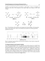
a) (b)
Fig. 1. Difference between electrochemical (a) and optical (b) measurement.
surface. The locus of electrical centres of ions adsorbed in the Helmholz layer (more
precisely centres of symmetry of ion electrical field) is called the inner Helmholz plane. The
outer Helmholz layer is formed by the space charge region which is created by interaction
between electrode and charged ions in solutions. The outer Helmholz plane is the locus of
centres of the nearest solvated ions with respect of to the electrode surface (Bard & Faulkner,
1980). The third layer is created by Nernst layer where the concentration differs from the
bulk concentration due to the diffusion of electro active compounds to the electrode surface.
The response of the sensor will depend on the structure of each of these layers and on the
chemical reactions which run in each of these layers. There are also fluctuations of
properties of each of this layer. It is obvious that these fluctuations will be averaged on the
electrode surface but not in the distance x. The electrochemical biosensor is prepared from
electrochemical sensor by immobilization of bioactive compound (Macholán, 1991; Turner et
al., 1987). The immobilized layer lies in the outer Helmholz layer and in the Nernst layer. It
assures not only the run of reaction which is responsible for sensor selectivity but it
influences the structure of inner Helmholz layer. The process of immobilization significantly
changes the specific adsorption on the active electrode. The influence of bioactive layer on
the structure of outer Helmholz layer and Nernst layer is dramatic. The bioactive membrane
changes the space distribution of the charge, solvation processes, pH equilibration in outer
Helmholz layer. The bioactive layer also changes the concentration distribution in Nernst
layer. The interactions are mutual. The presence of electrode and reactions on its surface
influences the bioactive membrane. The local changes of pH can move the reaction out of
pH optimum. Local changes of ionic strength can influence the reaction in bioactive
membrane (Kotyk et al., 1977). The situation with optical sensor is quite different. The beam
of light goes trough the analyzed solution and interacts with molecules. It interacts directly
with each molecule and there is no subsequent interaction in layer as in the case of
electrochemical sensors. Fluctuations in optical measurement also occur however these will
be averaged not only on the optical detector surface but also along the distance x along, the
path of beam. It assures better robustness of optical measurement. This demonstrates the
important role played by mass transport in electrochemical measurements and in
electrochemical biosensors (Dvořák & Koryta, 1983; Rieger, 1993; Riley, et al. 1987). The role
of mass transport can be shown experimentally. It is possible to measure the surface of
screen printed electrodes by SEM and confocal microscopy and compare the result with
Screen Printed Electrodes with Improved Mass Transfer
293
electrochemical measurement. This procedure is in detail described in (Schröper et al., 2008).
The importance of this measurement consists not only in the fact of obtaining the active area
of the sensor but experiments these can be considered as model of typical amperometric
measurement. The result is in fig. 2 and fig. 3.
Fig. 2. The surface structure of AC1.W1.RS (left panel) and AC1.W2.RS (right panel)
recorded by optical (upper and middle part) and scanning electron microscopy (bottom
part).
Fig. 2 shows the anaysis of gold and platinum active surface of electrodes by optical
microscopy and scanning electron microscopy. The comparison with electrochemical
measurement is in fig. 3. Independent methods show the active surface significantly bigger
as electrochemical measurement.
New Perspectives in Biosensors Technology and Applications
294
1,90
1,95
2,00
2,05
2,10
2,15
02468
R
AG
4,10
4,20
4,30
4,40
4,50
4,60
4,70
02 46
R
AG
(a) (b)
R
AG
0,00
0,50
1,00
1,50
2,00
2,50
02468
W1RS-Optical
W1RS-ElChem
R
AG
0,00
1,00
2,00
3,00
4,00
5,00
02 468
W2RS-Optical
W2RS-ElChem
(c) (d)
Fig. 3. The results of confocal microscope relation of active area to geometrical area (R
AG
)
measurement, a) (R
AG
) for the sensor AC1.W1.RS (Au) b) (R
AG
) for the sensor AC1.W2.RS
(PT). Comparison with electrochemical measurement c) Sensor AC1.W1.RS (Au) d) Sensor
AC1.W2.RS (Pt).
The surface properties of Au and Pt working electrodes prepared by screen printing (BVT
Technologies, a.s.) were studied on statistical data sets. The mean ratio of active to
geometrical surface (R
AG
) obtained by optical measurement is in Tab. 1.
Type of sensor Working electrode R
AG
Number of measurements
AC1.W1.RS Au 2.03 ± 0.04 (n = 7)
AC1.W2.RS Pt 4.35 ± 0.08 (n = 5)
Table 1. Optical measurement
(R
AG
) obtained by electrochemical measurement of the same sensors. Results for AC1.W1.RS
and AC1.W2.RS are as follows (Tab. 2).
Screen Printed Electrodes with Improved Mass Transfer
295
Type of sensor Working electrode R
AG
Number of measurements
AC1.W1.RS Au 0.61 ± 0.06 (n = 5)
AC1.W2.RS Pt 0.34 ± 0.20 (n = 6)
Table 2. Electrochemical measurement
Electrochemical results are approximately an order of magnitude lower than optical
measurement data (3x, 12x).
The simplest explanation for this difference can be explained by insufficient mass transport
and its poor reproducibility. The electrochemical reaction runs only on the upper edges of
the complicated electrode surface. This reaction shields the lower layers of the electrode
where no reaction takes place (see fig. 4). It is obvious that mass transport under such
conditions will be very sensitive to experimental arrangement namely stirring of the
solution. This also explains the difference between electrochemical determinations of active
surface measurement in the literature where results can differ in range by one order. This
shielding explains the low efficiency of nanostructures on the electrode surface (Fig. 4)
which was indirectly confirmed by experiments in (Maly et al., 2005). These results are valid
not only for special measurement as mentioned above but more generally for all
measurements based on the electrochemical principle.
(a) (b)
Fig. 4. Nanostructured (a) and planar (b) electrode of electrochemical sensor.
2. Properties by controlled mass transport
In the next section the improvement of screen printed electrochemical sensors and biosensor
will be demonstrated and wall jet cell by three techniques
- Microfluidic arrangement which uses a thin layer cell
- Rotated disc microelectrode
- Thermodiffusion
The improvement is based on controled and amplified mass transport from bulk of solution
to the active surface of electrode.
2.1 Microfluidic arrangement
The experimental arrangement of the microflow system (MFS) is illustrated in figure 5.
New Perspectives in Biosensors Technology and Applications
296
(a) (b)
(c) (d)
Fig. 5. a,b) Experimental arrangement of the Microflow system (Patent CZ 287676);
1) electrochemical vessel, 2) modified lid, 3) body of microflow insert, 4) driving shaft,
5) pump rotor, 6) sample mixing chamber, 7) sample pumping chamber, 8) mixing channel
outlet, 9) capillary, 10) microflow chamber, 11) thick film sensor, 12) mixing channel inlet,
13) driving belt, 14) motor, 15) inert gas input. c) Flow cell arranged in thin layer format.
d) Flow cell arranged in wall-jet format (Krejci et al., 2008).
A conventional electrochemical vessel (Rieger, 1993) (1) in figure 5 (TC1) (BVT Technologies,
a.s., Czech Republic) is covered by a modified lid (2) carrying the body of the microflow
insert (3). The driving shaft (4) located in the centre of the microflow insert is connected to
the pump rotor (5) immersed in the electrolyte/sample fluid. The electrolyte/sample fluid
comes to the pump rotor (5) via mixing channel inlet (12). The two chambers located above
the rotor fulfil two different functions. The first of the chambers (6) is connected via mixing
channel outlet (8) to the bulk of electrolyte/sample solution inside the electrochemical
vessel. The portion of the liquid being pumped through this passageway provides for
sufficient stirring of the solution inside the electrolyte vessel. The second chamber (7) helps
to guide the fluid coming from the rotor into the capillary (9) and into the electrode cell (10).
Screen Printed Electrodes with Improved Mass Transfer
297
The function of the narrow capillary is to stabilize the flow of the liquid before it enters into
the electrode cells. The overall design of the insert is such that only 1 – 5% of the liquid is
flowing through the chamber (7) and capillary (9), while bout 95 – 99% of it is pumped
through the chamber (6): and channel (8), ensuring intensive stirring of the solution. The
electrode cell (10) contains the integrated three-electrode amperometric sensor (11)
(AC1.W2.R1, BVT Technologies, a.s., Czech Republic; Fig. 6b). Following its passage past the
sensor, the liquid is returned from the electrode cell directly into the bulk of the
electrolyte/sample solution inside the vessel. The driving shaft (4) is connected by means of
an elastic belt (13) to the external motor (14). The entire electrochemical vessel with the
microflow insert immersed in the electrolyte/sample solution is placed in a thermostat bath
and the temperature is kept constant at 25 ± 0.1 °C. The tube (15) can be used for inert gas
introduction for work under inert atmosphere. A few other openings in the lid (2) are
provided for sample additions, insertion of a thermometer and for other accessories. The
arrangement is mainly destined for batch injection analysis. The principle was integrated
into the device MFS (BVT Technologies, a.s.) (Fig. 6a) (Krejci et al., 2008).
Fig. 6. a) Photo of the microflow system (MFS) device (BVT Technologies, a.s., Czech
Republic). b) Integrated three-electrode amperometric sensor (Patent CZ 291411)
(A: auxiliary electrode, R: reference electrode, W: working electrode) (Krejci et al., 2008).
The device can be equipped with two types of electrode cells (fig. 5, 10). The wall jet cell and
thin layer cell (fig. 5 c, d). In case of wall jet cell the stream of analyte flows from small
orifice of diameter a perpendicularly to the active surface of electrode. The current of
electrode in wall jet arrangement where the diameter of electrode active area is bigger than
jet opening is described by equation (1) (Painton & Mottola, 1983). The theory of wall-jet
hydrodynamic arrangement was originally derived by Matsuda (Matsuda, 1967; Yamada &
Matsuda, 1973). The more detailed description of jet flow is in excellent monography of
Polyanin (Polyanin et al., 2002).
3253
3
4124
0
1,15InFRaD Uc
(1)
New Perspectives in Biosensors Technology and Applications
298
where
n-Number electrons in reaction; F-Faraday constant [96 485 C.mol
-1
]; R-Radius of electrode
[m]; a-Diameter of jet [m]; D-Diffusion coefficient [m
2
.s
-1
]; υ-Kinematic viscosity [m
2
.s
-1
];
U-Velocity in the jet [m.s
-1
]; c
0
-Concentration [mol.l
-1
]; I-Current [A]
The important characterization of the cell is its conversion efficiency η. This quantity
describes the relation of actual current with respect of current produced by all electroactive
(active in case of biosensor) compounds entering the cell. Using data from Polyanin
(Polyanin et al., 2002) it can be evaluated as
32 5
11
3
41242
3
4
41.15
RD Q a
(2)
where
Q-volume flow of sample trough cell [m
3
.s
-1
]
The thin layer arrangement is characterized by electrode active surface placed in channel
with very small height. Important characterization of thin layer arrangement is that channel
height h is significantly smaller than channel width b (h << b) (see fig. 5c). There are many
different equations in literature which describes thin layer hydrodynamic arrangement.
They can by summarized as equation (4a) where different authors found different value
of constant k (Brunt & Bruins, 1979; Hanekamp & Nieuwkerk, 1980; Levich, 1947; Wranglén
et al., 1962). If the flow around electrode is stable and laminar then Matsuda derived
equation (4b) (Matsuda, 1967). More recent and excellent discussion namely concentrated
on was made by (Squires, 2008). Comprehensive analysis is also in (Polyanin et al., 2002).
If the length of electrode in the channel is higher than l (equation 3) then the sensor
measures in coulometric mode with 100% conversion. All electrochemical compounds are
reacted/converted at the electrode. In summary the current in case of thin layer cell is
described by equation (4c).
3
8
hQ
l
bD
(3)
where
D-Diffusion coefficient [-]; b-width of the channel [m]; h-channel height [m]; l-length of
electrode [m]
21
11
36
22
0
IknFDbl Uc
(4a)
221
333
0
1,47InFDAbUc
(4b)
0
InFQc
(4c)
where
k-lies in the range 0.68 – 0.83; b-width of the channel and electrode covering the wall of the
channel [m]; U-the linear velocity with laminar flow [m.s
-1
]; A-electrode area [m
2
];
Q-volume flow of electro-active material [m
3
. s
-1
]
The meaning of rest of symbols is same as in previous equations.
The conversion efficiency in above three cases is in equation (5)
Screen Printed Electrodes with Improved Mass Transfer
299
1
2
21
36
Qh
kD
lb
for (4a) (5a)
2
3
2
3
1.47
Q
D
h
for (4b) (5b)
1
for (4c) (5c)
2.2 Rotated disc microelectrode
A rotating disc electrode (RDE) is one exceptional example where the hydrodynamics
(Navier stokes equations) and convective mass transport can be solved in analytical
approximation. This means that relatively simple formulas exist that describe the electrode
response with sufficient precision. (Some authors states that the hydrodynamics and
convective diffusion at RDE can be analytically solved but this is not true.) The main
principles of RDE are theoretically described in the literature (Bard & Faulkner, 1980; Riger
1993; Riley et al., 1987) for example. However the exact and comprehensive description of
RDE physics can be found in Levich’s works (Levich, 1942, 1944, 1944, 1947). The results are
summarized in (Levich, 1962). The Levich derivation is based on results of Karman
(Karman, 1921). These results are used not only in Levich’s derivation but in many recent
works. Comprehensive analysis of RDE principle is in literature (Sajdlová, 2010; King et al.,
2005). An example of a RDE is shown in fig. 7. Classical RDE involve a platinum wire within
glass tubing sealed in the plastic body of the RDE. The shape of the insulating mantle has an
important role for the RDE function. It is obvious from the fact that Levich equation (6)
describing RDE response is valid for disc of infinite radius in semi infinite homogenous
media. This condition can not be fulfiled in real experimental conditions. However the
thickness of hydrodynamic boundary layer (0) is significantly lower than electrode
diameter. If the electrode is placed in distance from bottom of reaction vessel which is at
least 1 order bigger than (0) then Levich equation will be very good approximation of RDE
function. It means if the low angular speed is used the active surface of electrode is placed at
least 10 mm above bottom of reaction vessel (see tab. 3). Corruption of this condition leads
to hydrodynamic instability (Sajdlová, 2010). The electrical connection on the opposite end is
made by the means of a brush contact. The noise of electrode significantly depends on the
contact material and its construction. Will be had best experience with gold contact and
precious metal brush. The RDE can be prepared also as disposable insert (fig. 7) where the
active surface is made by screen-printing. The main advantage of RDE consists of possibility
to control the mass transport by rotation speed. If the experiments are done at different
velocities then the response can be extrapolated to infinite rotation speed where the mass
transport is eliminated and the response is determined by electrode kinetic only or by
immobilized enzyme kinetic if RDE is used as biosensor. It enables the optimization of
immobilization procedure including precise measurement of membrane properties
including enzyme biosensor membrane characterization. The RDE is characterized by two
most important parameters: 0 – thickness of the hydrodynamic boundary layer and
thickness of Nernst diffusion layer (), where the maximum changes of concentration with
respect of bulk concentration take place. Both parameters depend on angular velocity and
they can be expressed, as is shown in equations (6) and (7) (Levich, 1962).
New Perspectives in Biosensors Technology and Applications
300
0
3.6
(6)
3
0
0.5
D
(7)
where
υ- kinematics viscosity; ω-angular velocity; D-diffusion coefficient of analyte
Due to power 1/3 the dependence on υ is small. The typical values of
0
and for H2O and
glycerol are shown in table 3.
ω
[s-1]
H2O glycerol
Time
resolution
[s]
0
[µm]
[µm]
(D = 10-10
m2.s-1)
0
[µm]
[µm]
(D = 10-10 m2.s-
1)
1 1000 50 33000 33 16
10 330 16.5 10000 10 2.2
100 100 5 3300 3.3 0.16
1000 33 1.6 1000 1 0.022
Table 3. Typical values for H2O and glycerol.
The knowledge of the diffusion boundary layer enables to estimate the time resolution of
measurement as with RDE
2
D
. The typical values are in table 3 too.
The output current of RDE is derived from the Levich equation.
21
1
36
2
0
0.620InFAD c
(8)
where
n-Number of electron in the reaction,; F-Faraday constant [96 485 C.mol
-1
]; A-Area of
Electrode [m
2
]; D-Diffusion coefficient [m
2
.s
-1
]; υ-Kinematic viscosity [m
2
.s
-1
]; ω-Angular
velocity [s
-1
]; c
0
-Concentration [mol.l
-1
]; I-Current [A]
The conversion efficiency of RDE is
2
3
0,697
D
(9)
The conversion efficiency does not depend on electrode rotation speed and electrode
diameter. It values for small molecules in water is η
H2O
~ 0.01 and for glycerol η
glycerol
~ 10
-4
.
Equations (1, 4 and 8) are confirmed in the literature (King et al., 2005; Masavať et al., 2008;
Painton & Mottola, 1983; Tóth et al., 2004). Nearly all publications use these equations with
improper description of quantities, and improper coefficients. We have checked these
equations in the original literature and confirmed their validity. The fact, that majority of
publications which uses the equations (1, 4 and 8) for evaluation of electrode parameters or
membrane parameters, uses wrong equations; introduce some doubts about their reliability
and reliability of published data where these equations were used for calculation of
Screen Printed Electrodes with Improved Mass Transfer
301
diffusion coefficient or other parameters. In analytical practice the use of wrong formulas
does not play much important role because the measurement is calibrated and all equation
(1, 4 and 8) has a general structure I = konst c
0
. On the other hand it proves that the results
are not comparable between different experimental arrangements without cross calibration.
Implicitly the above low reliability of measurement is nothing else than insufficient
definitions of mass transport. All equations (1, 4 and 8) are nothing else than solution of
mass transport to the electrode under special conditions.
(a) (b)
Fig. 7. a, b) Mini-rotated disc electrode
The principle of RDE can be enhanced to move complicated hydro-dynamical arrangement.
It can be used for elimination of cross talk of array of electrodes (Dock et al., 2005; Sajdlová,
2010).
The comparison of conversion efficiencies for typical parameters used in measurement in
experimental part are summarized in tab. 4.
The parameters are:
diameter of jet nozzle a = 0.5 mm; radius of electrode R = 1 mm; height of channel
h = 0.3 mm; width of channel b = 1 mm; length of electrode l = 2 mm; diffusion coefficient
D = 10
-9
m
2
s
-1
; kinematics’ viscosity of water υ = 10
-6
m
2
s
-1
; angular speed of RDE ω = 60 s
-1
ηw (equation 2) 5 . 10-2
η5a (equation 5a) 3 . 10-2
η5b (equation 5b) 1 . 10-3
ηRDE (equation 9) 1 . 10-2
Ηchannel (equation 3)
100 mm
Table 4. Comparison of different conversion efficiencies for typical parameters of cell listed
in text.
Pt wire in glass
Screen printed active surface
New Perspectives in Biosensors Technology and Applications
302
2.3 Thermodiffusion
Electrochemical measurements are generally done under isothermal conditions. Thermal
gradient can be also used to improve the mass transport. The application of a controlled
temperature gradient between the working electrode surface and the solution, using
electrochemical sensors prepared on ceramic materials with extremely high heat
conductivity, enables that applied thermal gradient creates a the second driving force of
mass transport. This application of the Soret phenomenon increases the mass transfer in the
Nernst layer and enables more accurate control of the electrode response enhancement by a
combination of diffusion and thermodiffusion. The key physical phenomenon is difference
of thermal conductivity of ceramic and water solutions. The thermal conductivity of Al
2
O
3
ceramic is about 35 Wm
-1
K
-1
. The thermal conductivity of water is 0.6 Wm
-1
K
-1
. If the active
electrode is printed on the ceramic where on its opposite side just under working electrode
is placed heating then the thermal gradient can be significantly higher than concentration
gradient. The thermodiffusion coefficient is about 1-3 % of diffusion coefficient but at high
temperature gradients the thermodiffusion mass flow can be comparable with mass flow
driven by concentration gradient. It is important that thermodiffusion driving force can be
adjusted independently on the concentration by temperature of sensor. Cotrell-Soret
equation (10) has been derived in the literature (Krejčí, 2010).
012
1
1
T
D
InFAC s T T
T
(10)
where
0
1
1
()
nF E E
RT
Te
θ(T
1
) stresses the fact that due to high temperature conductivity of ceramic substrate of the
sensor, the temperature T
1
of the electrode surface is known. The Cotrell-Soret equation has
significant advantage with respect to Cotrell equation as it does not depend on the time. The
derived the Cotrell-Soret equation describing the steady-state response with an applied
temperature difference enables the measurement of electrode equilibrium potential at given
temperature.
The termodiffusion can remove the accumulation of reduced/oxidised compounds at closed
neighbourhood of electrode which is responsible for the hysteresis and complicated form of
cyclic voltametry (CV) response. The example of use of thermodiffusion for sensor response
improvement shows the ability of use of microelectronic technologies in electrochemical
sensor production. The screen-printed active electrode together with screen-printed heaters
and integrated thermometer Pt 1000 creates the electrochemical device which does not have
classical analogy.
2.4 Experimental
The above discussion about mass transport will be demonstrated on four examples which
demonstrate that screen-printed electrochemical sensor is very precise and sensitive device.
These examples are amperometric measurement of H
2
O
2
, which is important for biosensors
application where H
2
O
2
is product of enzymatic reaction (oxydases); measurement of
glucose oxidase by electrochemical sensor with immobilized enzyme; fast measurement of
enzyme activity; cyclic voltammetry at temperature gradient.
Screen Printed Electrodes with Improved Mass Transfer
303
Fig. 8. Schematic of the Soret system (the gap between the cone and electrode surface is 1 mm)
Calibration curve for H
2
O
2
measurement
1,000E-05
1,000E-04
1,000E-03
1,000E-02
1,000E-01
1,000E+00
1,000E+01
1,000E+02
1,000E+03
1,000E+04
1,000E+05
1,000E-06 1,000E-05 1,000E-04 1,000E-03 1,000E-02 1,000E-01 1,000E+00 1,000E+01 1,000E+02
Concentration [mM]
Current [nA]
RDE MFS
Fig. 9. Calibration curve for H
2
O
2
measurement (Krejci et al., 2008).
New Perspectives in Biosensors Technology and Applications
304
2.4.1 Amperometric measurement of H
2
O
2
The standard solution of hydrogen peroxide was prepared from a 3% stock solution
(Lachema, Brno, Czech Republic). The electrochemical vessel filled with 5.00 ml of the
working electrolyte (50 mM phosphate buffer, pH 7.0). The measurement was initiated by
recording the background current in the absence of an analyte. After its stabilization,
addition 50 µl aliquots of analytes (hydrogen peroxide) the changes in the current were
recorded. Detection of hydrogen peroxide was carried out by amperometric measurement at
the platinum working electrode of the AC1.W2.R1 sensor. The reaction chamber was wall-jet
(see fig 5). Figure 9 shows the response to stepwise concentration changes of hydrogen
peroxide spanning the range between 1.1 x 10
-9
to 8 x 10
-3
M. The extremely wide
measurement range and very low limit detection is result of working electrode
nanostructure (see fig. 2) and optimized mass transport in MFS device. The electrode is
sintered from Pt grains of size 100 – 1000 nm, which assures extremely large active area as it
is seen in fig. 2. Measurement was carried out with RDE under the same conditions. The
angular velocity was ω = 60 s
-1
. Experiments were done in 5 ml solution of phosphate buffer
and 50 µl aliquots of different concentrations of H
2
O
2
were added. The results are in the fig.
9 too. Under this condition the time the time resolution of RDE is 200 ms. The time
resolution of current recorder is 100 ms. It enables to follow the homogenization of
concentration in reaction vessel after analyte addition. The result can be seen in fig. 10.
The result on the fig. 10 demonstrates the dependence of the RDE response on its geometry.
It shows typical response of classical RDE and RDE with wider disk. In both cases the
material of electrode was polished platinum wire of 2 mm diameter melted in glass. The
angular velocity was the same 62 s
-1
. The response time of both electrodes was 200 ms at
sampling time 100 ms electronic recorder.
The electrode with a 3 mm diameter (Fig. 10a) has significantly lower noise (0.1 nA –
inserted noise analysis). The noise was analyzed when fluctuations of the signal
disappeared. These fluctuations are caused by homogenization of the concentration in the
bulk of solution. The homogenous concentration is reached after 180 s (3 min.). The
electrode with a 10 mm (additional disk but the active area is same as in case of previous
one) stabilizes significantly faster but with greater noise (7 nA – inserted noise analysis). The
fluctuation of signal differs significantly from the previous arrangement and the
concentration is homogenous in 15 s. Similar influence can be seen in dependence of signal
on the distance of RDE and bottom of reaction vessel (Sajdlova, 2010).
2.4.2 Measurement of glucose oxidase by electrochemical sensor with immobilized
enzyme
The measurement was done by the same procedure as in case of H
2
O
2
only the sensor with
immobilized glucose oxidase on the AC1.W2.RS was used in microfluidic system (MFS)
with wall-jet reaction chamber. In Fig. 11 there is the calibration curve. The flattening of the
calibration curves at higher concentrations is dictated by Michaelis-Menten kinetics. It is
possible to see that at lower levels the enzyme reaction approximates the first order kinetics
whereas at highest concentrations the reaction order approaches zero and the measured
current becomes independent of glucose (enzyme substrate) concentration (Mell & Maloy,
1974)
The wide measured concentration range and extremely low limit of detection is the result of
nanostructure as mentioned in section 1. The immobilization is made by this manner that
Screen Printed Electrodes with Improved Mass Transfer
305
(a)
(b)
Fig. 10. The response to addition of analyte of the RDE of diameter a) 3 mm in 5 ml buffer
and b) 10 mm diameter in 5 ml buffer.
New Perspectives in Biosensors Technology and Applications
306
the bioactive layer fills the free space between grains of Pt. It assures very tight connection
between immobilized enzyme and active Pt surface. The overall active layers thickness (Pt
and immobilized enzyme) is about 5 x 10
-3
mm. This assures the respond time less than 1 s.
Fig. 11. Calibration curves of glucose biosensor in stirred vessel (•) and in the microflow
system (○)
2.4.3 The measurement of soluble enzyme activity
The measurement of soluble enzymes activity is based on simplified Michaelis-Menten
equation (Macholán, 1991). It can be written on condition [S] > 100 K
M
i.e., the initial slope of
the record of reaction of substrate with enzyme is proportional to the enzyme activity. The
precision of approximation is better than 1 %. The absolute H
2
O
2
production in mols can be
recalculated for known volume of reaction vessel. It enables to calculate the activity of GOD
sample addition. The same experiment was done with RDE at same conditions (ω = 60 s
-1
),
see section 2.4.1. The measurement principle has been depicted in the fig. 12a on an example
of GOx. After the reaction vessel was filled with 5 ml of glucose solution of concentration 0.5
M ([S] ≈ 100 K
M
) the observation was started and the background current measurements
were recorded (A). The current response of the sensor was calibrated trough addition of
aliquot of product, i.e., H
2
O
2
(B). Then the solution of enzyme (GOx) was added (C). With
the reaction initiation the current started rising linearly (D). The slope of current rising
describes production of H
2
O
2
. The international unit of enzyme activity is defined for GOx
as an amount of enzyme which oxidized 1 µmol of D-glucose to gluconolacton and H
2
O
2
per 1 minute, at temperature 35 °C and at pH 5.1. The resulting calibration curve is in fig.
12b for MFS and RDE. The results of RDE are significantly better (lower limit of detection)
which is caused by better time resolution of RDE and better long term stability of RDE
current. Better long term stability enables higher resolution of extremely small changes of
current slope.
Screen Printed Electrodes with Improved Mass Transfer
307
(a)
(b)
1,00E-05
1,00E-04
1,00E-03
1,00E-02
1,00E-01
1,00E+00
1,00E+01
1,00E-06 1,00E-05 1,00E-04 1,00E-03 1,00E-02 1,00E-01 1,00E+00 1,00E+01
Log (activity of standard specimen) [IU]
Log (enzyme activity) [IU]
Calibration Line2
(c)
Fig. 12. a) Schematic view of enzyme activity measurement; A) addition of glucosse
concentration in vessel c
vessel
= 500 mM; B) addition of H
2
O
2
for calibration c
vessel
= 20.2 µM;
C) injection of GOx solution of unknown activity; D) H
2
O
2
production (478 µM/min).
b) Calibration curve for enzyme activity measurement using MFS (Krejci et al., 2008).
c) Calibration curve for enzyme activity measurement using RDE.
New Perspectives in Biosensors Technology and Applications
308
2.4.4 Cyclic voltammetry (CV) at temperature gradient
Measurements were performed in a device consisting of a glass cell TC1, conic stirrer and
connector KSA1 and electrochemical sensor AC1.W2.RS (H, T) (BVT Technologies, Czech
Republic). The AC1.W2.RS (H) electrochemical sensor bears platinum working and auxiliary
electrodes, a pseudo-reference silver electrode and a heating circuit. The cell TC1 was placed
in a small thermostat TK-1 (KEVA, Czech Republic). The whole system schematic is shown
in figure 8 (Krejci et al., 2010).
CV is the most common electrochemical method used to investigate the electrochemical
behaviour of an analyte. It enables the investigation of electrode reaction which occurs in the
proximity of electrode (Bard & Faulkner, 1980; Riger, 1993; Riley & Tomlinson, 1987). On the
other hand the hysteresis of cyclic voltammety curves which is related to mass transport
(one compounds is cumulated at the electrode during reduction scan which is reoxidized
under oxidation scan) makes the evaluation of CV quite difficult and more or less dependent
on the experience of evaluator. The improvement by the string does not work because of
causing noise. However the improving of mass transport by thermo diffusion significantly
improves the CV and facilitates its evaluation. The improvement can be seen in fig 13.
The improving mass transport by thermodiffusion improves the
CV
-5,00E-05
-4,00E-05
-3,00E-05
-2,00E-05
-1,00E-05
0,00E+00
1,00E-05
2,00E-05
3,00E-05
4,00E-05
-0,6 -0,4 -0,2 0 0,2 0,4 0,6
E [V]
I [A]
Cyclic voltammetry Cyclic voltammetry at temperature gradient Cyclic voltammetry at stirred
Fig. 13. The improving of mass transport by thermo diffusion
The samples of CV with thermo diffusion mass transport agree with equation (10) and it can
be used to measurement of E
0
at given temperature. Due to high thermal conductivity of
ceramic sensor base and precise temperature measurement using Pt 1000 thermometer
integrated in the proximity of working electrode the dependence of E
0
(T) can be measured.
The temperature difference about 10 – 40 °C significantly improves the mass transport and
measured current.
Screen Printed Electrodes with Improved Mass Transfer
309
3. Conclusion
The importance of mass transport has been discussed, namely with respect to screen printed
electrodes. The technology of screen printing and more general application of microelectronic
technologies open new area for electrochemical sensor application. However their effective
use relies on a clear and comprehensive understanding of mass transport between electrode
surface and bulk of solution. Advances with micro fluidics can significantly help, as
demonstrated using the micro fluidic system (MFS) with wall-jet and thin layer micro fluidic
arrangement. The classical arrangement of RDE can be miniaturized and produced at
significantly lower cost. Consequently disposable RDE can be used as highly efficient tools
for immobilized enzyme investigation, for optimization of the immobilization process and
enzymatic membrane kinetic measurement as well as other parameters important for the
immobilization process. Screen printing is a subset of Thick Film Technology used in
microelectronics. This enables the integration not only of the sensor active electrodes but
also heating elements and thermometers. Such complicated integrated sensors offer new
possibility to improve mass transport form the bulk of solution to the active electrode
surface. An example is thermo diffusion which may simplify the evaluation of CV. The
importance of mass transport was discussed, namely with respect of screen printed electrodes.
The technology of screen printing and more generally application of microelectronic
technologies opens new area of electrochemical sensor application.
4. Acknowledgment
This work was supported by the EU 7th Framework Programme 230749, EU 7th Framework
Programme 262007 and Czech Science Foundation KAN200520702. I would like to thank
Mark O’Connell from Probe Scientific for help with English text.
5. References
Bard, A.J.; Faulkner, L.R. (1980). Electrochemical Methods-Fundamentals and Applications.
John Wiley & Sons. New York. USA
Brunt K.; Bruins C.H.P. (1979). Evaluation of the characteristics of the differential
amperometric detector in combination with anion-exchange chromatography,
using l-ascorbic acid as test compound. Journal of Chromatografy A, Vol.172, Issue 1,
pp. 37-47
Clark, L.C.; Lyons, C. (1962). Ann.N.Y. Acad.Sci., Vol.102, pp. 29-45.
Dock, E.; Christenson, A.; Sapelnikova, S.; Krejci, J.; Emnes, J.; Ruzgas, T. (2005). A steady-
state and flow-through cell for screen-printed eight-electrode arrays. Analytica
Chimica Acta, Vol. 531, pp. 165–172.
Dvořák, J.; Koryta, J. (1983). Elektrochemie. Academia, nakladatelství ČSAV, Praha
Frost and Sullivan. (1994). Technnical insights, A.D.Litlle in Transducer aspects of biosensors,
Sethi, R.S., Biosensors and Bioelectronics 9, 243-264
Hanekamp H.B.; Nieuwkerk H.J. (1980). Anal. Chim., Acta 121, pp. 13-22.
Chan, F L.; Chang,W Y.; Kuo, L M.; Lin, Ch H.; Wang, S W.; Yang,Y S.; Lu, M. S-C.
(2008). IOP publishing journal of micromechanic and microengineering. Vol.18,
No.12.
Karman, T. (1921); Uber laminare and turbulente Reibung. Zeitschrift fur angewandte
Mathematik und Mechanik, Vol.1, No.4, pp. 233-252.
New Perspectives in Biosensors Technology and Applications
310
King, P.; Prasard,V. S. R. K.; Rao, G. H. (2005). Indian Journal of Chemical Technology, pp.
455-461.
Kotyk, A.; Horák, J. (1977) Enzymová kinetika. Academia, Praha
Krejci, J. (1988). Glucose sensor – Internal report. Research institute of medical engineering,
Brno
Krejci, J.; Lacina, K.; Vránová, H.; Grosmanová, Z. (2008). Microflow Vessel Improvning
Reproducibility and Sensitivity of Electrochemical measurements. Electroanalysis
20, No.23, pp. 2579-2586.
Krejci, J.; Sajdlová, Z.; Krejci, J., Jr.; Marvanek, T. (2010). Voltammetry under Controlled
Temperature Gradient. Sensors, Vol.10, pp. 6821-6835.
Levich, V.G. (1962) Physicochemical Hydrodynamics. Prentice Hall, Inc. Englewood Cliffs,
N.J.
Levich, V.G. (1947). Discuss. Faraday Soc. 1, Vol.37.
Levich, V.G. (1944). Acta Physicochem. USSR 19, Vol.113.
Levich, V.G. (1944). Acta Physicochem. USSR 19, Vol.117.
Levich, V.G. (1942). Acta Physicochem. USSR 17, Vol.257.
Levich, V.G. (1947). Disc. Faraday Soc. 1, Vo.37.
Macholán, L. (1991) Biocatalytic Membrane Electrodes in. Bioinstrumentation and
Biosensors. Wise, L. D. (ed.); Dekker, M. New York-Basel-Honkong
Maly, J.; Krejci, J.; Ilie, M.; Jakubka, L.; Masojidek, J.; Pilloton, R.; Sameh, K.; Steffan, P.;
Stryhal, Z.; Sugiura, M. (2005). Analytical and Bioanalytical Chemistry, Vol.381, pp.
1558-1567.
Masavať, P.; Liawruangrath, S. (2008). Chiang Mai J. Sci., Vol.35, pp. 355-369.
Matsuda H. (1967). J. Electroanal. Chem., Vol.15, pp. 325-336.
Matsuda H. (1967). J. Electroanal. Chem., Vol.15, pp. 109.
Mell, L.D.; Maloy, J.T. (1974). Anal. Chem., Vol.47, pp. 299-307.
Painton, C.C.; Mottola, H.A. (1983). Anal. Chim. Acta 154, pp. 1-16.
Polyanin, A.D.; Kutepov, A.M.; Vyazmin, A.V.; Kazenin, D.A. (2002). Hydrodynamics, Mass
and Heat Transfer in Chemical Engineering. London and New York, Taylor &
Francis
Riger, P.H. (1993). Electrochemistry. Chapman & Hall, New York
Riley, T.; Tomlinson, C. (1987) Principles of Electroanalytical Methods. New York: John
Wiley & Sons
Sajdlová, Z. (2010). Ph.D. thesis, Elactrochemical detector with electrodes array and rotating
disk
Sethi, R. S.; Gray Stephens, L. D.; Bruce, N. C.; Lowe, C. R An Improved Silicon Chip Based
Biosensor in “Proc.Third International Meeting on Chemical Sensors” Cleveland,
Ohio, USA, 116-117, 24/26 September (1990).
Sethi, R. S. Silicon Processing in the Fabrication of Biosensors. Semiconductor International,
NEC, Birmingham, UK, 14-16 March (1989).
Todd M. Squires; Robert J. Messinger & Scott R. Manalis. (2008) Nature Biotechnology
Tóth, K.; Štulík, K.; Kutner, W.; Fehér, Z.; Lindner, E. (2004). Pure Appl. Chem., Vol.76, No.6,
pp. 1119-1138
Turner, A.P.F.; Karube, I.; Wilson, G. S. (1987) eds.: “Biosensors: Fundamentals and
Applications”, Oxford Press, Oxford
Updike, S.J.; Hicks, G. P. (1986). The Enzyme Electrode. Nature 214, pp. 986-988
Wranglén G.; Nilsson O. (1962). Electro chim., Acta 7, pp. 121-137.
Yamada J.; Matsuda H. (1973). J. Electroanal. Chem., Acta 44, pp. 189-198.
New Perspectives in Biosensors Technology and Applications
312
2. Delta-Sigma pH-to-digital converter
The delta-sigma modulator is an attractive candidate for the sensor applications due to its
robust capability to process variations and high-resolution performance (Lemkin et al.,
1999). Furthermore, delta-sigma modulator can trade time for improvements of the
resolution and signal to noise ratio.
Direct sensor signal-to-digital converter provides digital output without the need for its
intermediate processing circuit. Direct capacitance-to-digital converters (Petkov et al., 2005)
and magnetic-to-digital converters (Kuo et al., 2001), based on the principles of the delta-
sigma technique, are suitable for sensors signal processing. In this study, direct pH-to-
digital converter based on delta-sigma modulator in fully integrated pH sensor readout
circuitry is proposed.
2.1 Conventional pH sensor readout system
The sensor readout system shown in Fig. 1 is the conventional approach to pH sensor
receiver architecture. With high Q off-chip filters (shaded in Fig. 1), this conventional
architecture is not amenable to a highly integrated solution. The off chip filters also must be
specific to a particular sensor.
Consider the propagation of a desired pH sensor signal through the readout path as shown
in the frequency plan. The pH sensor signal at the sensing membrane passes through an off-
chip filter and is amplified by the pre-amplifier or low-noise amplifier (LNA). Amplification
of the pH sensor signal is required to achieve adequate sensitivity by reducing the noise
contributions of environment noise in the receive path. After the pre-amplifier or LNA, the
sensor signal goes off-chip through the filter. The combination of the pH sensor signal and
filters rejects environment noise which is out off pH sensor signal bandwidth that must be
attenuated prior to offset cancellation circuit. The offset cancellation circuit is constructed by
a digital-to-analog converter and a differential amplifier with low gain. The general
correction method used in readout channel is successive approximation. The variable gain
amplifier (VGA) is used to reduce the dynamic range (DR) requirement of subsequent
stages. The most important design factor of variable gain amplifier is the total harmonic
distortion (THD). The variable gain amplifier must amplify the sensor signal without
distortion. Finally, anti-aliasing and analog-to-digital conversion (ADC) are performed.
ADC is required so that output bits can be recovered in the digital domain. The filter can be
performed in the analog domain using either continuous time or discrete time (switched-
capacitor) filters or in the digital domain. The choice of analog or digital selection impacts
the dynamic range requirements of the ADC and the programmability of the sensor readout
system.
Analog filter in front of the ADC must band-limit the incoming signal with enough stop
band rejection to remove the environment noise prior to sampling by the ADC. In alternate
way, the ADC must oversample enough so that the environment noise does not alias into
the desired frequency band and can be removed by a subsequent digital filter. Thus, from
the ADC design view, the bandwidth selection of sensor signal reduces to providing
adequate anti-aliasing in either the analog or digital domain. The analog filter must have
enough dynamic range and linearity to select the desired bandwidth in the presence of pH
sensor signal. Since all bandwidth select filtering is performed prior to the ADC, only a low
resolution ADC with enough bandwidth to digitize the desired bandwidth is required. One
implementation of the pass band processing block would employ a continuous time low
CMOS, Delta-Sigma pH-to-Digital Converter as
New Integrated Device for Potentiometric Biosensors Applications
313
pass analog filter in front of the ADC. This filter would be implemented by switched-
capacitor technology since the pH sensor signal is DC-like signal. Linearity considerations
dictate the signal-handling capability of the filter. Moreover, bandwidth selection can be
performed in the digital domain using an oversampled delta-sigma modulator followed by
a digital decimation filter.
ADC
DAC
Pre-Amplifier
Offset Cancellation
Low Pass Filter
Variable Gain Amplifier
Anti-aliasing Filter
pH Buffer Solution
Ag/AgCl
Sensing Membrane
Filter
Fig. 1. Block diagram of conventional pH sensor readout circuit
2.2 EGFET-operational amplifier
Ion sensitive field effect transistors (ISFETs) are emerging as important sensing devices in
the areas of environmental monitoring applications and biomedical applications (Bergveld,
1970). The ISFET used as a pH sensor is an integrated device composed of a conventional
ion selective membrane and a metal oxide semiconductor field effect transistor (MOSFET).
Extended gate field effect transistor (EGFET) is another structure to isolate field effect
transistor (FET) from chemical environment, in which a sensitive membrane is fabricated on
the end of the signal line extended from the gate electrode of FET (Spiegel et al., 1983).
EGFET has advantages over ISFET such as low cost, simple structure and ease to package
(Chin et al., 2001). Behavior of surface ion adsorption effect of the ISFET and EGFET are the
same (Chou et al., 2009). The much difference between ISFET and EGFET is the impedance
of sensing film. The gate electrode of EGFET must be high conductivity material to be a
sensing electrode that can transmit sensing signals easily.
The EGFET can be represented by a model as depicted in Fig. 2. It consists of a chemical part
and an MOS transistor part. In chemical part, two series capacitances and represent the
equivalent Gouy-Chapman and Helmholtz capacitance (Grattarola et al., 1992), which has
been developed by site-binding model and the electrical double-layer theory (Fung et al.,
1986). Two voltage sources and are connected in series to denote the voltage components of
chemical threshold voltage of EGFET. The chemical threshold voltage consists of two
potentials –Ψ
eo
+χ
sol
, χ
sol
in which is a constant with respect to the pH value, and Ψ
eo
is the
only chemical parameter that is responsible for pH sensitivity of EGFET. χ
sol
, with a typical
value of 50 mV, is the surface dipole potential of the solvent being independent of pH (Chan
et al., 2007). The sensitivity of Ψ
eo
, which is defined as the change of Ψ
eo
with respect to a
change of the pH value of the solution ΔΨ
eo
/ΔpH , has already been explained by the Hal
and Eijkel’s theory (Van Hal et al., 1995). This is elaborated by using the general accepted
site-binding model and the Gouy-Chapman-Stern model to yield on:
eo
Δψ
KT
2.303
ΔpH q
=
−⋅⋅α (1)
New Perspectives in Biosensors Technology and Applications
314
where K is the Boltzmann constant, T is the absolute temperature, q is the magnitude of the
electron charge, α is a dimensionless sensitivity parameter, with the value ranging between
0 and 1.
V
CHEM
V
REF
C
GOUY
C
HELM
D
S
G
Fig. 2. EGFET modeling components
The other physical constants have their usual meanings. Therefore, the voltage source
becomes:
sol
CHEM
KT
V 2.303 pH (
χ
C )
q
=α⋅+− (2)
where the first term is pH-dependent and the constant terms in the parentheses are pH-
independent.
Like the standard MOSFET, for a long-channel EGFET operating in a saturation region, the
drain current can be expressed as
()
2
DS OX GS TH(EGFET)
1W
I μCV V
2L
=−
(3)
where μC
ox
is the process transconductance parameter, W/L is the aspect ratio. Moreover,
the EGFET threshold voltage combined with the MOS transistor counterpart which includes
body effect in a four-terminal device can be unified as
TH(EGFET) CHEM TH
VVV
=
+ (4)
where V
TH
is the threshold voltage of the MOS transistor.
As this potential is pH-independent, it can be viewed as a common-mode input signal for an
EGFET interface circuit in any pH buffer solution and can be nullified during system
calibration and measurement procedures. The SnO
2
/ITO glass, fabricated by sputtering
SnO
2
on the conductive ITO glass, was used as a pH-sensitive membrane of EGFET-
operational amplifier. The SnO
2
thin films were formed by the radio frequency sputtering
system at a substrate temperature of 150°C. Mixed sputtering gases included O
2
and Ar.
Thickness of the SnO
2
thin film was about 2000 Å. The ITO glasses were supplied by the
Wintek corporation. The coating thickness of ITO was about 230 Å. The sheet resistance of
ITO is 50-100 Ω/□. The conducting line was bound from the ITO layer and packaged by
epoxy after the thin film was deposited. The commercial buffer solutions were used as the
test solutions. The micro slide glass and corning 7059 glass were purchased from Kimax
Glass Instrument and Tekstarter corporation. The deposition parameters are summarized as
follows:
CMOS, Delta-Sigma pH-to-Digital Converter as
New Integrated Device for Potentiometric Biosensors Applications
315
1. Deposition rate is 20 Å/s.
2. Deposition pressure is 20 e-3 Torr.
3. Background pressure is 2×e-6 Torr.
4. The Ar/O
2
ratio is 4:1.
5. Substrate temperature is 150°C.
The fabrication processes of sensing structure were summarized as follows and its cross-
section is shown in Fig. 3.
1. Clean the silicon substrate.
2. SnO
2
was deposited on ITO about 3000Å by sputtering method.
3. Bounding and packaging by epoxy.
SnO
2
ExpoxyExpoxy
ITO
Glass substrate Conductor line
Fig. 3. Cross-section of SnO2/ITO glass sensing membrane
The operation of the extended-gate field effect transistor is very similar to that of a
conventional MOS, except that an additional sensing structure is dipped in the buffer
solution. In the study of pH sensitivity of the SnO
2
/ITO glass, the SnO
2
/ITO glass sensing
membrane was connected to an instrumentation amplifier (Yin et al., 2000). The
instrumentation amplifier was used to measure output response of the SnO
2
/ITO glass in
the pH buffer solutions, and the result shows that the sensing membrane, SnO
2
/ITO glass,
has a linear pH sensitivity of approximately 59.3mV/pH in the ion concentration ranging
between pH 2 and 10. To evaluate the hysteresis characteristic of the SnO
2
/ITO glass
sensing membrane, we measured the output offset voltage after solution change such as
pH7ÆpH4ÆpH7 and pH 7ÆpH10ÆpH7. The results show that the hysteresis of the
SnO
2
/ITO glass sensing membrane is about 4.2mV. For the sensor signal measurement, we
need an interface circuit that tracks the threshold voltage (or the flat-band voltage) of the
EGFET as the electrolyte pH is varied. A more practical solution to monitor the sensor signal
with electronics is to view the EGFET as a circuit component in an integrated circuit rather
than as an add-on sensor whose output signal is further processed. In this work, we adapt
the EGFET-operational amplifier approach of utilizing the EGFET as one of the input
transistors in the differential stage of an operational amplifier shown as in Fig. 4.
Circuit functions of the EGFET-operational amplifier as follows: when the EGFET-
operational amplifier is configured as a voltage follower (β=1), the output voltage is equal to
the input voltage; any difference in threshold voltages and bias currents between the two
input transistors at the differential input stage will also appear at the output. Writing out the
terms of the threshold voltages of the MOSFET and the EGFET explicitly, the output of the
EGFET-operational amplifier is as followings:
OUT TH CHEM
V ΔVV
=
= (5)