Advanced Trends in Wireless Communications Part 11 pot
Bạn đang xem bản rút gọn của tài liệu. Xem và tải ngay bản đầy đủ của tài liệu tại đây (2.67 MB, 35 trang )
Advanced Trends in Wireless Communications
340
and Communications Technology (NICT) on FSO communications indicates that compact
communications terminals will have good applicability in the future. NICT has developed a
non-mechanical, compact optical terminal equipped with a two-dimensional laser array for
space communications, and this paper considered its application toward indoor optical
wireless communications.
In section 2, we propose the concept of a compact free-space laser communications terminal
via the first implementation of an 8 × 8 VCSEL array. This optical system has no
mechanically moving parts. This compact terminal can receive optical communications
signals from multiple platforms and transmit multiple optical communications beams to the
counter terminals. Such an optical system can therefore serve as a MIMO system. Section 3
presents the system analysis of the optical link budget for indoor optical wireless
communications between an optical base station and distributed stations. Background noise
is estimated during the daytime and eye safety is discussed with respect to the optical base
station and the distributed stations.
2. Conceptual terminal design
2.1 System configuration
Figure 1 shows the configuration of the proposed compact laser communications
transceiver. The laser beam from the counter terminal passes through the telescope lens, is
reflected from the beam splitter, and is detected by the CCD sensor. The CCD sensor detects
the direction of the counter terminal’s line of sight, and one of the array lasers is selected
according to the direction of the signal received by the CCD. A CCD with a pixel size equal
to that of the XGA (1280 × 1024) is used. The centroid of the pixels is calculated in the
computer, and the laser beam corresponding to the direction of the centroid is turned on.
Figure 2 shows a photograph of the manufactured compact laser communications
transceiver and control computer system. With this configuration, multiple inputs from
multiple platforms are possible with the parallel laser spot detection processing, and MIMO
configuration is also possible (Short et al., 1991).
Driver
Laser array
Lens
Tx data input
BS
Rx
Tx
CCD
Capture
board
Digital
I/O
PC
Multichannels
Rx
Tx
Fig. 1. Configuration of the proposed compact laser communications transceiver
Non-mechanical Compact Optical Transceiver for Optical Wireless Communications
341
2.2 Optical part of the transceiver
The laser beam is transmitted from the two-dimensional laser array through the beam
splitter and telescope lens. The beam is selected by the centroid calculation in the computer.
The beam divergence angle of the selected laser beam covers the angular interval between
adjacent laser arrays (Cap et al., 2007). Two adjacent laser beams are turned on
simultaneously to ensure that the laser transmission is not interrupted and to maintain a
constant optical intensity at the counter terminal. Figure 3 shows the beam transmission
configuration for a two-dimensional laser array. With this transmission method, the
transmitted laser beam is not interrupted during the tracking of the counter terminal. Each
laser beam is combined by an interval at the half width at half maximum (HWHM).
Therefore, if the two adjacent laser beams are turned on simultaneously the optical intensity
can be almost constant at the counter terminal.
Control PC
Electrical part
Optical part
Fig. 2. Manufactured compact laser communications transceiver
Laser array
Lens
Overlap
Beam divergence
Laser beam
Fig. 3. Laser beam transmission method
Advanced Trends in Wireless Communications
342
Fig. 4. 8 × 8 VCSEL array
Fig. 5. Optical part of the compact laser communication transceiver
For the transmitter, we use an 8 × 8 VCSEL array, as shown in Figure 4, for the first
evaluation model. VCSELs were chosen because they are easy to arrange in an array, there
are no mechanical parts, and they are readily available. The maximum output power of one
Non-mechanical Compact Optical Transceiver for Optical Wireless Communications
343
pixel is 4 mW at a wavelength of 850 nm, as shown in Table 1. The laser diode can be
modulated at above 2.5 GHz. All the VCSELs could be turned on individually. The beam
divergence for this evaluation model was designed to be 2 degrees for one VCSEL.
Fig. 6. Electrical part of the compact laser communication transceiver
Parameter Value
Array number 64 (8 × 8)
Maximum output power of one pixel 4 mW
Wavelength 850 nm
Beam divergence angle 20-30 degrees
Minimum frequency response 2.5 GHz
Table 1. VCSEL array specifications
Figure 5 shows the optical part of the manufactured compact laser communications
transceiver. The small telescope consists of nine lenses. The VSCEL is mounted at the end of
the small telescope and the CCD sensor is mounted on the upper side of the telescope, as
shown in Fig. 5. The size of the optical part of the telescope (lens mount) is 13.5 × 6 × 11 cm,
power consumption is less than 10 W, and mass is 1 kg, as shown in Table 2. Commercial-
off-the-shelf (COTS) transceivers usually have a tracking system and a COTS transceiver has
power consumption of 20 W and mass of about 8 kg at 1.25 Gbps. Our system, however, has
no mechanical tracking system; thus there is the potential of reduced mass, power, and
volume in the proposed transceiver.
2.3 Electrical part of the transceiver
Laser beams in the VCSEL array are modulated according to the received laser spot
extracted by the control computer system, as shown in Fig. 1. Two 32-channel digital I/O
Advanced Trends in Wireless Communications
344
boards are installed and can transmit data at a rate of 25 Mbps. Figure 6 shows a photograph
of the electrical part of the manufactured laser driver. The electrical part, as shown in Fig. 6,
can drive 64 channels of the VCSELs by the selected signal from the digital I/O boards. The
laser diode is driven at an average power of 2 mW by the driver electronics. The electrical
part of the compact laser communications transceiver has mass of 3.1 kg, size of 27 × 26 × 10
cm, and power consumption of less than 10 W, as shown in Table 2.
Resource Value
Mass 1 kg
Optical part
Size
(lens mount)
15 × 12 × 12 cm
(13.5 × 6 × 11 cm)
Mass 3.1 kg
Size 27 × 26 × 10 cm
Electrical
part
Power < 10 W
Table 2. Compact laser communication transceiver resources
Fig. 7. Optical base station and distributed optical station layout
3. System analysis and experimental results
3.1 Link budget analysis
Table 3 summarizes the results of the link budget analysis for the proposed compact optical
transceiver applied to indoor optical wireless communications. The optical link is designed
to connect an optical base station on the ceiling with distributed optical terminals in a room,
as shown in Fig. 7. The output laser power for a pixel of the VCSEL array is assumed to be 2
mW at 850 nm wavelength. The beam divergence angle is set at 0.33 rad for a single laser
pixel for the full width at 1/e
2
maximum (FWe
2
M), and the angular coverage of the
transmitter is 180° for a 8 × 8 array, which is sufficient to cover the number of distributed
optical terminals in the room. The overlap of the beams is set to occur at the HWHM. The
Non-mechanical Compact Optical Transceiver for Optical Wireless Communications
345
beam pointing error can be considered as zero because the transmitting power can be
doubled by turning on the adjacent two VCSELs simultaneously.
If stations A, B, or C simultaneously communicate with the base station, the spatial diversity
can be performed by the different VCSEL lasers. If some stations can be within one laser
beam, time-division multiple-access (TDMA), CDMA, or frequency-division multiple-access
(FDMA) can be used for the communication scheme. By using these techniques, MIMO can
be achieved with a single photo detector with the sufficient field of view (FOV) and
appropriate optical filter. Figure 8 shows an example image of simultaneous two-target
tracking measured by CCD. Figures 9 and 10 show the CCD pixels for simultaneous two-
target tracking when one target is fixed and the other is oscillating at 5 and 10 Hz,
respectively. These results show successful simultaneous two-target tracking, demonstrating
the capability of MIMO for free-space laser communications.
Item Unit Value
TX power mW 2.0
dBm 3.0
Laser array pixel size - 8x8
Beam diameter at telescope μm 3.2
TX beam divergence rad 0.33
Angular coverage deg 180.0
TX optics loss dB -2.0
Wavelength m 8.50E-07
Average pointing loss dB 0.0
TX gain dB 24.6
Distance m 10.0
Space loss dB -163.4
Atmospheric transmission dB 0.0
RX antenna diameter cm 5.0
RX gain dB 105.3
RX optics loss dB -2.0
RX power dBm -34.5
Data rate bps 1.00E+09
Sensitivity (@BER of 10
-6
) photons/bit 1000
dBm -36.3
Average margin for BER dB
1.9
MPE W/m
2
20.0
Margin for MPE dB 0.4
Table 3. Link budget analysis between an optical base station on the ceiling and distributed
optical terminals in a room
Advanced Trends in Wireless Communications
346
3.2 Background noise and eye safety
If we consider the FOV of about 10 degrees, the background level during the daytime
becomes about -44 dBm by using an optical filter with 1 nm optical bandwidth and 5 cm
aperture diameter. In this case, the signal-to-noise ratio (SNR) can be about 10 dB for the
received level at a BER of 10
-6
, as shown in Table 3. Due to the background, a detector array
with FOV of 10 degrees should be used to achieve a 1 Gbps data rate. Pointing therefore
needs to be achieved at the receiver.
The link distance is assumed to be 10 m from the optical base station on the ceiling to the
distributed optical stations. If we use on-off-keying (OOK) non-return-to-zero (NRZ) data
transmission with a receiving aperture with a 5 cm diameter in the proposed system, the
link margin will be 1.9 dB at a data rate of 1 Gbps with BER of 10
-6
. In order to keep the eyes
safe from laser beam radiation, the irradiance from the optical base station should be lower
than the maximum permissible exposure (MPE) beyond a distance of 50 cm. On the other
hand, the laser beam in the distributed stations close to the users can be never transmitted
until when the laser beam from the optical base station is received as the protocol. If the
laser beam is received by the distributed optical stations it will not contact the human eyes.
Therefore, by this procedure the eye safety can be preserved in the distributed optical
stations close to the users.
As shown in Table 3, the proposed non-mechanical method can be applied to terrestrial free-
space laser communications. If the proposed terminal can be greatly compacted, mobile
users can use the high-data-rate optical link without a mechanical tracking system on the
ground, like a digital camera. Setting up the optical transceivers is easy and their installation
is uncomplicated. In the future, applicable fields for the optical transceivers will include not
only satellite communications but also high-speed cell phone communications, wireless
LAN, mobile communications, and building-to-building fixed high data rate
communications with no difficulties. The reliability of VCSELs, however, must be examined
in the future based on the given environment.
Fig. 8. Example of simultaneous two-target tracking measured by CCD
Non-mechanical Compact Optical Transceiver for Optical Wireless Communications
347
0
50
100
150
200
250
300
350
400
00.511.52
CCD position [pixel]
Time [sec]
Target 1
Target 2
Fig. 9. CCD pixels for simultaneous two-target tracking when one target is fixed and the
other is oscillating at 5 Hz
0
50
100
150
200
250
300
350
400
00.511.52
CCD position [pixel]
Time [sec]
Target 1
Target 2
Fig. 10. CCD pixels for simultaneous two-target tracking when one target is fixed and the
other is oscillating at 10 Hz
3.3 Future issues
The system proposed in this paper was developed for space communications but applied for
indoor networks. Indoor optical wireless systems face stiff competition from future WiFi
(802.11n) and 3GPP evolutions (IMT-Advanced), which will have data rates respectively
exceeding 300 Mbps and 100 Mbps. The Gbps-class optical indoor wireless system may,
Advanced Trends in Wireless Communications
348
however, play an interesting role in high data transmission and supplementing for
drawbacks of frequency and bandwidth allocation and interference problems between RF
and optical systems. Optical wireless systems should not compete with each other.
Standardization efforts will be carried out with respect to the supplementing and also to
ensure Gbps-class optical wireless interfaces on future user devices.
4. Conclusion
We have presented a non-mechanical and highly compact optical transceiver. A VCSEL
array is used in the transceiver, and the laser pixel turned on depends on the direction of the
counter terminal from which the CCD receives a signal. The mass, volume, and power of the
proposed system can be reduced because it contains no mechanically movable structures.
This study used an 8 × 8 VCSEL, which, to the best of our knowledge, is the first such
implementation. The VCSEL number can be increased for improving the number of counter
terminals but the MPE must be reduced, which is the tradeoff in the system design, and a
novel protocol was proposed for eye safety. A simultaneous two-target tracking test was
performed and demonstrated the capability of MIMO for free-space laser communications.
As there are no regulatory restrictions on the use of the optical frequency, the proposed
compact laser communications transceiver will be useful not only for satellites but also
terrestrial optical wireless communications in future applications.
5. References
Arimoto, Y.; Toyoshima, M., Toyoda, M., Takahashi, T., Shikatani, M. & Araki K. (1995).
Preliminary result on laser communication experiment using Engineering Test
Satellite-VI (ETS-VI), Proc. SPIE, Vol. 2381, pp. 151–158
Cap, G. A.; Refai, H. H. & Sluss, Jr., J. J. (2007). Omnidirectional free-space optical (FSO)
receivers, Proc. SPIE, Vol. 6551-26, pp. 1–8
Chan, V. W. S. (2003). Optical satellite networks, Journal of Lightwave Technology, Vol. 21, pp.
2811–2827
Djahani, P. & Kahn, J. M., (1999). Analysis of Infrared Wireless Links Employing Multi-
Beam Transmitters and Imaging Diversity Receivers, Global Telecommunications
Conference - Globecorn'99, 1999.
Hyde, G. & Edelson, B. I. (1997). Laser satellite communications: Current status and
directions, Space Policy, Vol. 13, pp. 47–54
Hamzeh, B. & Kavehrad, M., (2004). OCDMA-coded free-space optical links for wireless
optical-mesh networks, IEEE Transactions on Communications, Vol. 52, No. 12, pp.
2165–2174
Jono, T.; Takayama, Y., Kura, N., Ohinata, K., Koyama, Y., Shiratama, K., Sodnik, Z.,
Demelenne, B. Bird, A. & Arai, K. (2006). OICETS on-orbit laser communication
experiments, Proc. SPIE, Vol. 6105, pp. 13–23
Kim, I. I.; Riley, B., Wong, N. M., Mitchell, M., Brown, W., Hakakha, H., Adhikari, P. &
Korevaar, E. J. (2001). Lessons learned from the STRV-2 satellite-to-ground
lasercom experiment, Proc. SPIE, Vol. 4272, pp. 1–15
Lightsey, P. A. (1994). Scintillation in ground-to-space and retroreflected laser beams, Opt.
Eng., Vol. 33, No. 8, pp. 2535–2543
Non-mechanical Compact Optical Transceiver for Optical Wireless Communications
349
Minh, H. L., O’Brien, D., Faulkner, G., Zeng, L., Lee, K., Jung, D., Oh, Y., and Won, E. T.,
(2009). 100-Mb/s NRZ Visible Light Communications Using a Postequalized White
LED, IEEE Photonics Technology Letters, Vol. 21, No. 15, pp. 1063–1065
Miyashita, N.; Konoue, K., Omagari, K., Imai, K., Yabe, H., Miyamoto, K., Iljic, T., Usuda,
T., Fujiwara, K., Masumoto, S., Konda, Y., Sugita, S., Yamanaka T., & Matunaga, S.
(2006). Ground operation and flight report of Pico-satellite Cute-1.7 + APD,
International Symposium on Space Technology and Science (25th ISTS)
Nakaya, K.; Konoue, K., Sawada, H., Ui, K., Okada, H., Miyashita, N., Iai, M., Urabe, T.,
Yamaguchi, N., Kashiwa, M., Omagari, K., Morita, I. & Matunaga, S. (2003). Tokyo
Tech CubeSat: CUTE-I -Design and development of flight model and future plan-,
21st AIAA International Communication Satellite System Conference & Exhibit,
Yokohama, Vol. 2003-2388, April 15–19
Nielsen, T. T.; Oppenhaeuser, G., Laurent, B. & Planche, G. (2002). In-orbit test results of the
optical intersatellite link, SILEX. A milestone in satellite communication,
Proceedings of the 53rd International Astronautical Congress, Vol. IAC-02-M.2.01, pp. 1–
11, Houston, October
Parand, F., Faulkner, G. E. & O’Brien, D. C. (2003). Cellular tracked optical wireless
demonstration link, IEE Proc. Optoelectron., Vol. 150, No. 5, pp. 490–496
Reyes, M.; Chueca, S., Alonso, A., Viera, T. & Sodnik, Z. (2003). Analysis of the preliminary
optical links between ARTEMIS and the Optical Ground Station, Proc. SPIE, Vol.
4821, pp. 33–43
Short, R. C.; Cosgrove, M., Clark, D. L. & Oleski, P. (1991) Performance of a demonstration
system for simultaneous laser beacon tracking and low data rate optical
communications with multiple platforms, Proc. SPIE, Vol. 1417, pp. 464–475
Takayama, Y.; Jono, T., Toyoshima, M. Kunimori, H., Giggenbach, D., Perlot, N., Knapek,
M., Shiratama, K., Abe, J. & Arai, K. (2007) Tracking and pointing characteristics of
OICETS optical terminal in communication demonstrations with ground stations
(Invited Paper), Proc. SPIE, Vol. 6457A, 6457A-06
Toyoshima, M. (2005a). Trends in satellite communications and the role of optical free-space
communications [Invited], Journal of Optical Networking, Vol. 4, pp. 300–311
Toyoshima, M.; Yamakawa, S., Yamawaki, T., Arai, K., Reyes, M., Alonso, A., Sodnik, Z. &
Demelenne, B. (2005b). Long-term statistics of laser beam propagation in an optical
ground-to-geostationary satellite communications link, IEEE Trans. Antennas and
Propagat., Vol. 53, No. 2, pp. 842–850
Toyoshima, M.; Kunimori, H., Jono, T., Takayama, Y. & Arai, K. (2006) Measurement of
atmospheric turbulence in a ground-to-low earth orbit optical link, 2006 Joint
Conference on Satellite Communications (JC-SAT 2006), Vol. SAT2006-37, pp. 119–124,
Jeju-do, Korea, October 20
Toyoshima, M.; Takahashi, T., Suzuki, K., Kimura, S., Takizawa, K., Kuri, T., Klaus, W.,
Toyoda, M., Kunimori, H., Jono, T., Takayama, Y. & Arai, K. (2007). Laser beam
propagation in ground-to-OICETS laser communication experiments, Proc. SPIE,
Vol. 6551, 6551-09
Wilson, K. E.; Lesh, J. R., Araki, K. & Arimoto Y. (1998). Overview of the Ground-to-Orbit
Lasercom Demonstration, Space Communications, Vol. 15, pp. 89–95
Advanced Trends in Wireless Communications
350
Wu, H., & Kavehrad, M., (2007). Availability Evaluation of Ground-to-Air Hybrid FSO/RF
Links, International Journal of Wireless Information Networks, Vol. 14, No. 1, pp.33–45
Zeng, L., O’Brien, D. C., Minh, H. L., Faulkner, G. E., Lee, K., Jung, D., Oh, Y. & Won, E. T.,
(2009). High Data Rate Multiple Input Multiple Output (MIMO) Optical Wireless
Communications Using White LED Lighting, IEEE Journal on Selected Areas in
Communications, Vol. 27, No. 9, pp. 1654–1662
Part 7
Communication Protocols and Strategies
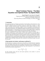
19
Efficient Medium Access Control Protocols for
Broadband Wireless Communications
Suvit Nakpeerayuth
1
, Lunchakorn Wuttisittikulkij
1
, Pisit Vanichchanunt
2
,
Warakorn Srichavengsup
3
, Norrarat Wattanamongkhol
1
, Robithoh Annur
1
,
Muhammad Saadi
4
, Kamalas Wannakong
1
and Siwaruk Siwamogsatham
5
1
Chulalongkorn University
2
King Mongkut's University of Technology North Bangkok
3
Thai-Nichi Institute of Technology
4
University of Management and Technology
5
National Electronics and Computer Technology Center
1,2,3,5
Thailand
4
Pakistan
1. Introduction
In wireless communication systems, an efficient medium access control (MAC) protocol is
usually required so that multiple wireless stations can efficiently share the scarcely-limited
wireless channel. In a typical wireless environment, wireless stations are usually
geographically distributed over a service area and are not synchronized. As a consequence,
wireless stations are typically required to contend for transmission opportunities. In general,
if the MAC protocol is not properly designed, channel contention may cause serious
transmission collisions and can considerably degrade the system throughput performance.
Over the past several decades, numerous MAC protocols have been developed to smartly
utilize the wireless channel, e.g., ALOHA (Abramson, 1970), carrier-sense multiple access
(CSMA) (Kleinrock & Tobagi, 1975; Tobagi & Hunt, 1980), and many other variants (Tasaka
& Ishibashi, 1984; Karn, 1990; Frigon, et al., 2001; Amitay & Greenstein, 1994). These
conventional MAC protocols have been successfully deployed in practice for different
applications and environments, including the widely adopted IEEE 802.11 a/b/g/n wireless
local area network systems, the emerging IEEE 802.16 (WiMAX) wireless metropolitan area
network, the IEEE 802.15.4 (Zigbee) wireless sensor networks, and various famous MAC
protocols for satellite communication networks. In addition, the emerging multimedia
technologies in recent years have continuously driven the requirements for higher and
higher system transmission throughput. In such an environment, the round trip
propagation delays between the base station and wireless stations have increasingly become
relatively larger and larger compared with a packet transmission time. As a consequence, a
fair deal of recent research work has been directed toward the renewed studies of efficient
MAC schemes for systems with relatively large propagation delays.
This chapter overviews the existing MAC technologies and summarizes recent research
advancements toward the improvements and analysis of various MAC protocols. In
Advanced Trends in Wireless Communications
354
particular, a class of efficient modified random channel contention and reservation schemes
based on our proposed work (Sivamok, et al, 2001; Srichavengsup, et al, 2005) is presented
with a complete discussion of mathematical performance evaluation and numerical results.
2. Pure ALOHA
In 1970, Norman Abramson and his colleagues at the University of Hawaii proposed a new
medium access control, known as ALOHA or Pure ALOHA, as part of the ALOHA system,
that aimed to interconnect a central computer at the university main campus near Honolulu
to remote consoles at colleges and research institutes on several islands using UHF radio
communications. Two 100 kHz channels at 407.350 MHz and 413.475 MHz are assigned for
transmission in each direction, each operating at a bit rate of 24,000 baud. In the ALOHA
system, information is transmitted in the form of packets, and all packets are of fixed length,
i.e. 88 bytes (8 bytes for header and 80 bytes for data). Therefore, the packet transmission
time is about 29 msec and this time becomes 34 msec when information for receiver
synchronization is included.
The basic idea of the Pure ALOHA protocol is simple, but elegant: each station is allowed to
send its packet whenever it has a packet ready for transmission. Since a common channel is
shared among stations, collision between packets from different stations will result when
they are sent at nearly the same time. Fig. 1 shows an example of packet transmissions and
possible collisions of four stations contending for the same channel. Those packets that are
overlapped in time are collided and destroyed. In this example, only two packet
transmissions are successful, and the rest of them need to be retransmitted.
Time
T 2T 3T
A
B
C
D
Station
04T
5T 6T
Collision Collision
Fig. 1. Packet transmissions in a Pure ALOHA system
After a packet transmission, the sending station waits for an acknowledgement from the
receiver to indicate successful transmission of the packet. However, if no acknowledgement
is returned within a time-out period, the sending station assumes that the packet is
destroyed and starts a retransmission procedure. In principle, the time-out period must be
set at least equal to the maximum possible round trip delay between two most widely
separated stations to ensure correct functioning of the protocol. Obviously, if the colliding
stations try to retransmit their packets immediately, they will collide again. Therefore, each
station is required to wait for a random amount of time, called back-off time, before
resending the packet. This random back-off mechanism is intended to keep multiple stations
from trying to transmit at the same time again which helps reduce probability of collisions.
The back-off time is randomly chosen from the range
[0, 2 1]
k
−
multiplied by the maximum
Efficient Medium Access Control Protocols for Broadband Wireless Communications
355
propagation delay (or alternatively the packet transmission time), where k is the number of
previous unsuccessful transmission attempts. This means that the mean value of back-off
time is doubled each time the packet is retransmitted. This retransmission is repeated until
either the packet is acknowledged or a predetermined number of retransmissions, typically
set as 15 attempts, is exceeded.
To see how well such a simple protocol will perform, a throughput analysis for the Pure
ALOHA protocol is carried out with the following basic assumptions. There is an infinite
number of stations that are generating new packets according to a Poisson process with an
average of
S packets per packet transmission time. All packets are of equal length and the
packet transmission time is
T seconds. Packets that fail to reach the intended receivers due
to collisions are retransmitted. Since retransmitted packets are vulnerable to collisions too,
they will also require retransmission again if not successful. Let us define
G as the average
number of packets both new and retransmitted combined per packet transmission time.
Obviously,
G is always greater than or equal to S . It is further assumed that generations of
these combined packets during one packet transmission time also follow Poisson
distribution. The ratio of
S to G is essentially the probability of a successful packet, that is
S
S
P
G
=
(1)
Time
Tt −
Tt +
Tt 2+
A
B
Vulnerable period = 2T
Collision
Collision
t
Fig. 2. Vulnerable time for Pure ALOHA
Fig. 2 shows the vulnerable time of a shaded packet, which starts its transmission at time
t
and finishes at
tT
+
. This shaded packet is successfully transmitted, as long as no other
packet is transmitted during the interval
tT
−
to tT
+
, so-called vulnerable period. If
another packet begins a transmission within the interval
tT
−
to t , such as packet B, the
end of this packet will collide with the start of the shaded packet. If another packet begins a
transmission within the interval
t to tT
+
, such as packet A, the start of this packet will
collide with the end of the shaded packet. Based on this observation, it is clear that the
shaded packet has a vulnerable period of
2T , in which if no other packet starts any packet
transmission, no collision will occur and the shaded packet will reach the receiver
successfully. Therefore, the probability of a successful packet
()
s
P in Pure ALOHA is equal
to the probability of no generation of packet within
2T seconds. Since the probability of k
packets are generated within 2 times the packet transmission time according to the Poisson
distribution is given by:
Advanced Trends in Wireless Communications
356
2
(2 )
Pr[ ]
!
kG
Ge
k
k
−
= (2)
the probability of no packet generated is
2
Pr[ 0]
G
ke
−
== (3)
By combining Equations (1) and (3), we get
2G
SGe
−
= (4)
This relation between
G which represents the total offered traffic on the channel and S
which represents the throughput of the Pure ALOHA system is plotted in Fig. 3. It shows
that initially at low traffic load throughput increases with increasing offered traffic up to a
maximum of
1/2 0.184e
=
occurring at a value of 0.5.G
=
A further increase of traffic leads
to a higher collision probability due to more intense contention, causing a reduction of
throughput.
0 0.5 1 1.5 2 2.5 3
0
0.05
0.1
0.15
0.2
0.25
0.3
0.35
0.4
Offered traffic (G)
Throughput (S)
Slotted ALOHA
Pure ALOHA
Fig. 3. Throughput versus offered traffic for Pure and Slotted ALOHA
3. Slotted ALOHA
In 1972, Robert introduced a simple modification to Pure ALOHA for improved
performance. Time is divided into slots, where each time slot has a fixed size equal to the
time required to transmit one packet. Unlike Pure ALOHA, a station is allowed to start a
packet transmission only at the beginning of each time slot. If the station has a packet ready
to send, it must wait until the beginning of the next time slot. If more than one packet are
transmitted in the same slot, they are collided and retransmissions are required. In case of
collision, each station involved retransmits its packet in each subsequent slot with
probability
p
until success. Since a packet transmission is confined within the slot
boundary, when a collision between packets from different stations occurs, they will overlap
completely. This means that the vulnerable period for Slotted ALOHA is reduced by half
compared to Pure ALOHA. This modified protocol is commonly known as Slotted ALOHA.
Fig. 4 shows an example of packet transmissions and possible collisions in the Slotted
ALOHA system. Notice that most packets are generated during a slot interval, and they are
Efficient Medium Access Control Protocols for Broadband Wireless Communications
357
kept waiting until the start of the next slot before transmitted. Indeed, the traffic pattern is
deliberately selected to be the same as in Fig. 1 for comparison purpose with Pure ALOHA.
Slotted ALOHA appears to reduce collision in this example; only two packets are collided
compared to four in case of Pure ALOHA.
Since the throughput of Slotted ALOHA can be analyzed in the same way as Pure ALOHA
except that the vulnerable period is now equal to the packet transmission time, the
probability of no other packet is sent in the same slot is
Pr[ 0]
G
ke
−
== (5)
and thus the relation between throughput and offered traffic for Slotted ALOHA can be
obtained as
G
SGe
−
=
(6)
Time
T 2T 3T
A
B
C
D
Station
04T
5T 6T
Collision
Packet
arrival
Waiting time
Fig. 4. Packet transmissions in a Slotted ALOHA system
Fig. 3 illustrates the comparison of throughput performance of Pure and Slotted ALOHA.
The maximum throughput of Slotted ALOHA is 1 / 0.368e
=
, which occurs at 1G = ; this is
doubled of that of Pure ALOHA. As we can see, the efficiency of Pure ALOHA can be
improved by the introduced time slot structure. However, time synchronization is required
to align stations to the slot structure. One possible solution is to have a central station send a
kind of clock signal at a regular interval.
Both Pure and Slotted ALOHA have advantageous features. First, they are highly
decentralized and quite simple to implement, especially Pure ALOHA. Second, when there
is only one active station, the station can continuously transmit its packets at the maximum
channel capacity. These two key features make the ALOHA system particularly useful for
large population of stations each with light and burst traffic demand. However, due to their
simplicity of operation, ALOHA makes inefficient use of channel capacity and is low in
throughput performance.
4. Carrier Sense Multiple Access (CSMA)
Pure ALOHA has a shortcoming in that a station still transmits its packet even if the channel
is already occupied by another station. Such collisions can be avoided, if only the sending
station senses the channel before using it. This led to the development of an important class
Advanced Trends in Wireless Communications
358
of MAC protocols called Carrier Sense Multiple Access (CSMA). A station that wishes to
send a packet is required to sense if the channel is busy or idle first. If the channel is sensed
busy, the station must wait until the channel becomes idle again before making any
transmission. Such a “listen before talk” strategy helps reduce unnecessary packet collisions,
thereby increasing channel efficiency. Fig. 5 shows an example of possible packet
transmissions in a CSMA system for the same traffic situation as in Fig. 1 of Pure ALOHA.
As we can see, each packet waits until the channel becomes idle before transmission and in
this particular example, no collisions occur at all; all packets are successfully transmitted.
Time
T 2T 3T
A
B
C
D
Station
04T
5T 6T
Packet
arrival
Waiting time
Fig. 5. Packet transmissions in a CSMA system
A B C
Time
0
t
2
t
1
t
Packet
transmission time
Packet B only
Packet C only
Packets B and C
Fig. 6. An example of a collision in CSMA
Even if the channel is sensed by all stations before their transmissions, collisions can
nonetheless occur in CSMA due to propagation delay. That is, when a station transmits a
packet, it takes time equal to propagation delay before all other stations detect this
transmission. During this period, if another station has a packet ready to send and not yet
detect that transmitted packet, it will send its own packet and a collision will result. Fig. 6
shows an example of a possible collision of two packets in CSMA. Station B starts a packet
transmission at time
0
t
. A moment later at time
1
t
, station A receives the first bit of the
packet and thus refrains from transmission. However, at time
2
t
station C has a packet
ready to send and does not detect any signal on the channel, so it starts a packet
transmission, which of course will collide with the packet from station B. Therefore, the
vulnerable period of CSMA is equal to the propagation delay, which is the time required for
a signal to traverse from one station to another at the opposite end. This means that the
smaller the propagation delay between two most widely separated stations gets, the less the
Efficient Medium Access Control Protocols for Broadband Wireless Communications
359
collisions are, and the more the performance improvement can be achieved. Note however
that even if the propagation delay is zero, collisions still occur. Consider two or more
persistent stations, awaiting the channel to become idle. As soon as the ongoing packet
transmission is ended, all persistent stations will transmit their packets immediately, and
results in a definite collision.
Sense the
channel
Is the
channel
free?
Yes
No
A packet
ready to send
Wait for a
random amount
of time
Sense the
channel
Is the
channel
free?
Yes
No
A packet
ready to send
Sense the
channel
Is the
channel
free?
Yes
No
A packet
ready to send
Send the
packet with
probability p
Yes
No
Is the
packet
sent?
Wait for a
slot time
Is the
channel
already
occupied?
No
Yes
Send the
packet
Send the
packet
End End
Wait a
back-off
delay
End
(a) 1-persistent CSMA (b) Nonpersistent CSMA
(c) p-persistent CSMA
Fig. 7. Flow diagrams for CSMA systems
CSMA has several variations which differ in the strategy used in waiting for the channel to
become idle. Three most commonly known strategies, namely 1-persistent CSMA,
nonpersistent CSMA and p-persistent CSMA, are considered below. Note that Fig. 7 shows
flow diagrams for these three persistent strategies.
1-persistent CSMA When a station is ready for a packet transmission, it first senses
whether the channel is busy or idle. If the channel is idle, it sends the packet immediately.
If the channel is busy, the station keeps on sensing the channel until it becomes idle and
then sends the packet immediately. The problem of 1-persistent CSMA is that if two
stations have a packet ready to send in the middle of another packet transmission. Both
stations will wait until the end of the transmission and start their packet transmissions at
the same time, guaranteeing a collision. Thus, 1-persistent CSMA can be perceived as a
greedy strategy.
Nonpersistent CSMA When a station wishes to transmit a packet, it first senses the channel
to see if it is idle, if so the station sends the packet immediately. If the channel is busy,
instead of continuing to listen for the channel to become idle and transmitting immediately,
Advanced Trends in Wireless Communications
360
it waits a random amount of time, then tries again. In contrast to 1-persistent CSMA,
nonpersistent CSMA is much less greedy. Therefore, in high load situations, there is less
chance of collisions occurring. On the other hand, in low load conditions, the channel
capacity is left unused despite some ready stations.
p-Persistent CSMA When a station has a packet ready to send, it first senses the channel. If
the channel is sensed busy, the station keeps on sensing the channel until it becomes idle
and uses the following procedure. Note that this same procedure is applied if the channel is
sensed idle right from the start. The station transmits its packet with probability
p
, and
delays one time slot with probability
1
p
−
, where the duration of a time slot is set equal to
or greater than the maximum propagation delay. If the station decides to delay one time
slot, it checks whether the skipped slot has been occupied by another station. If it is, the
station assumes as if there is a collision and starts its back-off procedure. Otherwise, the
station repeats the same procedure as before. That is, it transmits the packet with probability
p
, and delays one time slot with probability 1
p
−
, and so on.
Fig. 8 shows an example of packet transmissions in each of the three CSMA systems for the
same packet arriving scenario. Station A is the first to have a packet ready to send and then
followed by stations B and C. For 1-persistent CSMA as shown in Fig. 8(a), a packet from
station A is transmitted immediately as it arrives because the channel is sensed idle.
Packets from stations B and C arrive while the channel is busy, hence they wait until the
end of packet A transmission and start their transmissions immediately, resulting a
collision. Both of them start a back-off procedure, by delaying their next attempt by a
random amount of time. In this example, station C selects a shorter back-off time, so it
begins a packet transmission before station B. As a result, when station B wishes to
retransmit its packet, the channel is already occupied by station C. So station B waits until
the end of transmission and then sends its packet. For nonpersistent CSMA as shown in
Fig. 8(b), similar to the previous case packet A is successfully transmitted as it arrives first
and finds the channel idle. Packets from stations B and C arrive a little while later when the
channel is already occupied by station A, they are rescheduled for later transmission. After
a random delay, the packet from C is transmitted. During its transmission, the packet from
B tries again, but unfortunately finds the channel busy, so it is rescheduled again. After
another random delay later, the packet from B is finally transmitted successfully. For p-
persistent CSMA as shown in Fig. 8(c), unlike the previous two schemes station A that has
a packet ready to send first and finds the channel idle does not transmit its packet
immediately. Instead it waits until the beginning of the next slot and makes a decision
based on the p-persistent CSMA’s rule. That is, it transmits its packet with probability
p
,
and delays one time slot with probability
1
p
−
. In this example, station A does not send its
packet in the first slot, but it does in the second. When packets from stations B and C
arrive, the channel is already used by station A, so they wait until the end of the packet
transmission. Then the same p-persistent CSMA’s rule as before is applied. In this example,
packet B decides to send its packet in the third slot. Once station C learns at the end of the
third slot that the channel is already taken by other station it assumes as if there is a
collision and starts its back-off procedure. After a random back-off time later, station C try
to retransmit with the same rule and it sends its packet in the second slot. It should be
noted that the packet transmission time is assumed to be a multiple integer number of the
propagation delay.
Efficient Medium Access Control Protocols for Broadband Wireless Communications
361
A
A
B
C
Station
B
C
Collision
C
B
Retransmitted
Retransmitted
B waits until channel
becomes idle
B waits until
channel becomes
idle
C waits until channel
becomes idle
Packet
arrival
Random back-off
time for B
Random back-off
time for C
Time
(a) 1-persistent CSMA
A
A
B
C
Station
C
B
Packet
arrival
Packet C rescheduled
for transmission
Packet B rescheduled
for transmission
Channel unused
despite ready stations
Time
(b) Nonpersistent CSMA
A
A
B
C
Station
C
B
B waits until channel
becomes idle
C waits until channel
becomes idle
Packet
arrival
Random back-off
time for C
Time
(c) p-persistent CSMA
Fig. 8. An example of packet transmissions in different CSMA systems
5. Performance analysis of nonpersistent CSMA
Like other CSMA protocols, the nonpersistent CSMA reduces interferences from collision by
listening to the channel before packet transmission. If the channel is busy, the stations
reschedule the packet transmission to some random time in the future. To analyze the
performance, we assume that the offered traffic rate which is the sum of the new arrival rate
and the retransmission rate is constant and follows the Poisson point process. The average
retransmission delay is also assumed to be large compared to the transmission time of each
packet. From Fig. 9, a packet from station A arrives at time t and is immediately sent out
through the channel, because the channel is sensed idle. As it takes another
τ
seconds for
the packet to reach other stations, if there are other stations that have a packet ready to send
during t to
t
τ
+ , then they send their packets, causing inevitable collisions. So, the
nonpersistent CSMA has a vulnerable period of
τ
. In this example, two other stations B and
Advanced Trends in Wireless Communications
362
C each send a packet a moment later with station C being the last station to send during this
vulnerable period. As a result, all these three packets need to be retransmited. The duration
that there is one or more packet transmitted is referred to as the transmission period (TP). A
transmission period can be a successful transmission period or an unsuccessful transmission
period depending on whether there is collision or not. The time duration between two TPs
will be referred to as an idle period. A cycle of the transmission along the time axis consists
of a busy period B and an idle period I, where the busy period can be a successful or
unsuccessful TP. Let us define a useful transmission period U as the time duration that the
channel carries useful information without collision in a cycle. From the renewal theory, the
average channel utilization can be expressed as
U
S
BI
=
+
(7)
where
""
stands for the average.
A
A
Station
Vulnerable period
Time
Idle period
Unsuccessful transmission period
B
B
Y
T
τ
τ
T
τ
t
τ+t
C
C
A
Busy period
Successful transmission period
Busy period
τ+++tYT
Fig. 9. The busy and idle periods of the nonpersistent CSMA
Let T be the packet time and g be the offered traffic rate (the number of packets per second).
A TP is successful if there is no other packet transmitted in the vulnerable period
(, )tt
τ
+
and the useful transmission time is T. This occurs with the probability of
g
e
τ
−
and we get
g
UTe
τ
−
= (8)
Let t + Y be the time that the last packet arrives in the vulnerable period (which is the packet
from station C in Fig. 9). For an unsuccessful transmission period, the busy period B
includes a packet time T, Y, and
τ
which is the time for the last bit of the packet to leave the
channel.
BTY
τ
=
++ (9)
and the cumulative distribution function of Y is
()
( ) Pr{ } Pr{noarrival occurs in an interval ( , )}
,
Y
gy
Fy Y y t Yt
ey
τ
τ
τ
−−
=≤= ++
=≤
(10)
Efficient Medium Access Control Protocols for Broadband Wireless Communications
363
The average of Y is
1
(1 )
g
Ye
g
τ
τ
−
=− − (11)
Since the mean of inter-arrival time is 1/g, and it is assumed to be large compared to T, the
average of the idle period is
1
I
g
=
(12)
Substituting
U , B and I into (7), we obtain
11
2(1)
(1 2 / )
(1 2 )
g
g
g
g
aG
aG
Te
S
Te
gg
gTe
gT T e
Ge
Gae
τ
τ
τ
τ
τ
τ
−
−
−
−
−
−
=
+
−− +
=
++
=
++
, (13)
where
/aT
τ
=
is the propagation time relative to the packet time and GgT
=
is the offered
traffic rate per packet time.
A
A
Station
Propagation delay
Time
Idle period
Unsuccessful
transmission
period
B
B
C
Busy periodBusy per iod
T
τ
C
B
A
Unsuccessful
transmission
period
Successful
transmission
period
A
C
Unsuccessful
transmission
period
Successful
transmission
period
B
There is a packet ready to transmit.
Fig. 10. The busy and idle periods of the slotted nonpersistent CSMA
For slotted nonpersistent CSMA, the time duration of each slot is set to
τ
and the packet time
T is an integer multiple of
τ
(see Fig. 10 for details). When there is a packet ready to send, each
station waits for the beginning of the next slot and senses whether the channel is idle. If so, the
packet will be sent otherwise the packet is rescheduled for transmission later on. The
probability mass function (PMF) of the idle period is a geometric function of the form