Advances in Biomimetics Part 5 potx
Bạn đang xem bản rút gọn của tài liệu. Xem và tải ngay bản đầy đủ của tài liệu tại đây (9.55 MB, 35 trang )
Advances in Biomimetics
132
500 nm
A
D
B
C
10 μm
10 20 30 40 50 60 70
0
2000
4000
6000
8000
10000
(004)
(002)
2θ (
o
)
Intensity (a.u.)
500 nm
A
D
B
C
10 μm
10 20 30 40 50 60 70
0
2000
4000
6000
8000
10000
(004)
(002)
2θ (
o
)
Intensity (a.u.)
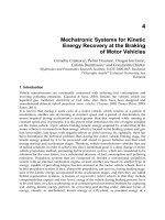
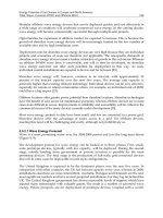
Fig. 2. Electrophoretic assembly of gibbsite nanoplatelets. (A) Photograph of a free-standing
gibbsite film. (B) Top-view SEM image of the sample in (A). (C) Cross-sectional view of the
same sample. (D) XRD patterns of the gibbsite film in (A). Adapted from Lin, Huang et al.
2009.
The oriented deposition of gibbsite nanoplatelets in a direct-current (dc) electric field can be
understood by considering the charge distribution on the gibbsite surfaces due to different
isoelectric points at faces (pH ~ 10) and edges (pH ~ 7). The pH of the bath in the
electrophoretic experiments is close to 7, resulting in positively charged surfaces and almost
neutral edges. Therefore, the applied electric field exerts a force only on the surfaces of the
gibbsite platelets and Brownian motion could provide sufficient torque to re-orient
perpendicular particles to face the ITO electrode. Once being close to the electrode, the
gibbsite nanoplatelets will be forced to align parallel to the electrode surface as this
orientation is more energetically favorable than the perpendicular one. If the duration of the
electrophoretic process is long enough, almost all gibbsite platelets can be deposited on the
ITO electrode.
4.2 Filling nanoplatelet assemblies with ETPTA
After oriented deposition, polymer-gibbsite nanocomposites can then be made by filling the
interstitials between the aligned nanoplatelets with photo-curable monomers, followed by
photopolymerization. We choose a non-volatile monomer, ethoxylated trimethylolpropane
triacrylate (ETPTA, M.W. 428, viscosity 60 cps), to form the nanocomposites. The monomer
with 1% photoinitiator (Darocur 1173, Ciba-Geigy) is spin-coated at 4000 rpm for 1 min to
infiltrate the electroplated gibbsite film and then polymerized by exposure to ultraviolet
radiation. The resulting nanocomposite film becomes highly transparent (Fig. 3A) due to the
matching of refractive index between the gibbsite platelets and the polymer matrix. The
normal-incidence transmission measurement as shown in Fig. 3B shows the free-standing
nanocomposite film exhibits high transmittance (> 80%) for most of the visible wavelengths.
As the reflection (
R) from an interface between two materials with refractive index of n
1
and
n
2
is governed by Fresnel’s equation(Macleod 2001):
Bioinspired Assembly of Inorganic Nanoplatelets for Reinforced Polymer Nanocomposites
133
12 12
R[(n )/( )]nnn
=
−+ (3)
A
D
B
C
10 μm
400 500 600 700 800
0
20
40
60
80
100
Transmission (%)
Wavelength (nm)
10 20 30 40 50 60 70
0
2000
4000
6000
8000
(004)
(002)
Intensity (a.u.)
2θ (
o
)
A
D
B
C
10 μm
400 500 600 700 800
0
20
40
60
80
100
Transmission (%)
Wavelength (nm)
10 20 30 40 50 60 70
0
2000
4000
6000
8000
(004)
(002)
Intensity (a.u.)
2θ (
o
)
A
D
B
C
10 μm
400 500 600 700 800
0
20
40
60
80
100
Transmission (%)
Wavelength (nm)
10 20 30 40 50 60 70
0
2000
4000
6000
8000
(004)
(002)
Intensity (a.u.)
2θ (
o
)
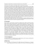
Fig. 3. Free-standing gibbsite-ETPTA nanocomposite. (A) Photograph of a transparent
nanocomposite film. (B) Normal-incidence transmission spectrum of the sample in (A). (C)
Cross-sectional SEM image of the same film. (D) XRD patterns of the same sample. Adapted
from Lin, Huang et al. 2009.
we can estimate the normal-incidence reflection from each air-nanocomposite interface to be
about 4%. Thus, the optical scattering and absorption caused by the nanocomposite itself is
ca. 10%. This suggests the polymer matrix has infiltrated most interstitial spaces between the
aligned gibbsite nanoplatelets. The cross-sectional SEM image in Fig. 3C shows the
nanocomposite retains the layered structure of the original electroplated gibbsite film. Thin
wetting layers of ETPTA (~ 1 μm thick) are observed on the surfaces of the film. The
oriented arrangement of the nanoplatelets is also maintained throughout the polymer
infiltration process as confirmed by the distinctive (002) and (004) peaks of the XRD
spectrum shown in Fig. 3D.
4.3 Composition analysis
The ceramic weight fraction of the ETPTA-gibbsite nanocomposite film is determined by
thermogravimetric analysis (TGA) as shown in Fig. 4. From the TGA curve and the
corresponding weight loss rate, it is apparent that two thermal degradation processes occur.
One happens at ~ 250°C and corresponds to the degradation of the polymer matrix; while
another occurs at ~ 350°C and is due to the decomposition reaction of gibbsite:
3232
2Al(OH) Al O 3H O→+ (4)
Based on the residue mass percentage (45.65%) and assuming the ash is solely Al
2
O
3
, we can
estimate the weight fraction of gibbsite nanoplatelets in the original nanocomposite film to
be ~ 0.70. Considering the density of gibbsite (~ 2.4 g/cm
3
) and ETPTA (~ 1.0 g/cm
3
), the
volume fraction of gibbsite nanoplatelets in the nanocomposite is ca. 0.50. The complete
Advances in Biomimetics
134
infiltration of ETPTA between the electroplated gibbsite platelets is further confirmed by the
selective dissolution of gibbsite in a 2% hydrochloric acid aqueous solution. This results in
the formation of a self-standing porous membrane with stacked hexagon-shaped pores,
which are negative replica of the assembled gibbsite platelets.
Fig. 4. Thermogravimetric analysis of a gibbsite-ETPTA nanocomposite. Adapted from Lin,
Huang et al. 2009.
4.4 Mechanical test
The mechanical properties of the biomimetic polymer nanocomposites are evaluated by
tensile tests. We compare the tensile strength for three types of thin films, including pure
ETPTA, gibbsite-ETPTA, and TPM-modified gibbsite-ETPTA. The surface hydroxyl groups
of gibbsite nanoplatelets can be easily modified by reacting with 3-(trimethoxysilyl)propyl
methacrylate (TPM) through the well-established silane coupling reaction. This results in the
formation of surface-modified particles with dangling acrylate bonds that can be crosslinked
with the acrylate-based ETPTA matrix. The colloidal stability and the surface charge of the
resulting nanoplatelets are not affected by this surface modification process as confirmed by
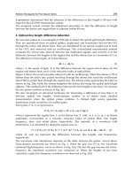
TEM and zeta potential measurement. Fig. 5 shows the tensile stress versus strain curves for
the above three types of films. The gibbsite-ETPTA nanocomposite displays ~ 2 times higher
strength and ~ 3 times higher modulus when compared with pure ETPTA polymer. Even
more remarkable improvement occurs when TPM-gibbsite platelets are crosslinked with the
ETPTA matrix. We observe ~ 4 times higher strength and nearly one order of magnitude
higher modulus than pure polymer. This agrees with early studies that reveal the crucial
role played by the covalent linkage between the ceramic fillers and the organic matrix in
determining the mechanical properties of the artificial nacreous composites.
We also conduct a simple calculation to evaluate if the measured mechanical properties of
the gibbsite-ETPTA nanocomposites are reasonable. For a polymer matrix having a yield
shear strength τ
y
and strong bonding to gibbsite nanoplatelet surface (e.g., TPM-modified
gibbsites), the tensile strength of the composite (σ
c
) can be calculated using the volume
fraction of nanoplatelets (V
p
), the nanoplatelet aspect ratio (s), and the tensile strength of the
nanoplatelets (σ
p
) and of the polymer matrix (σ
m
), as(Bonderer, Studart et al. 2008)
Bioinspired Assembly of Inorganic Nanoplatelets for Reinforced Polymer Nanocomposites
135
0.00 0.01 0.02 0.03
0
20
40
60
0.00 0.01 0.02 0.03
0
20
40
60
0.00 0.01 0.02 0.03
0
10
20
30
40
50
60
Strain
Gibbiste+ETPTA
ETPTA
Tensile Stress (MPa)
TPM-modified Gibbsite+ETPTA
0.00 0.01 0.02 0.03
0
20
40
60
0.00 0.01 0.02 0.03
0
20
40
60
0.00 0.01 0.02 0.03
0
10
20
30
40
50
60
Strain
Gibbiste+ETPTA
ETPTA
Tensile Stress (MPa)
TPM-modified Gibbsite+ETPTA
Fig. 5. Tensile stress versus strain curves for plain ETPTA film, ETPTA-gibbsite
nanocomposite, and TPM-modified ETPTA-gibbsite nanocomposite. Adapted from Lin,
Huang et al. 2009.
cPP Pm
σαV σ (1 V )σ
=
+− (5)
For the gibbsite nanoplatelet which has a relatively small aspect ratio (s ~ 12 to 18), the
factor α in equation 3 can be estimated as
y
P
ατs/2σ
=
(6)
From the above TGA analysis, the volume fraction of gibbsite nanoplatelets in the polymer
nanocomposite is ~ 0.50. If we take s = 15, equation 3 can then be simplified as
myc
0.5σ3.75τσ += (7)
For acrylate-based polymer (like ETPTA), the yield shear strength should be close to its
tensile strength. Equation 7 can further be simplified as σ
c
~ 4.25σ
m
. This indicates that the
strength of the nanocomposite is about fourfold of the strength of the polymer matrix,
agreeing with our experimental result.
5. PVA-gibbsite nanocomposites
5.1 Single-step electrophoretic deposition of PVA-gibbsite nanocomposites
The electrophoretic deposition of PVA-gibbsite nanocomposites is also carried out using the
same parallel sandwich cell as described above. The high-molecular weight PVA (Mw
89,000-98,000) is neutrally charged in the electrophoretic bath and can be adsorbed on the
surfaces of gibbsite nanoplatelets as water-soluble binders to cement electrodeposited
gibbsite nanoplatelets together and also prevent the deposits from cracking. Fig. 6A shows a
photograph of a PVA-gibbsite nanocomposite formed on an ITO cathode. The film can be
easily peeled off from the electrode surface by using a sharp razor blade. The resulting self-
standing film is flexible and transparent, which is different from gibbsite deposits. Optical
transmission measurement at normal-incidence shows the film exhibits 60-80%
transmittance for most of the visible wavelengths. Top-view SEM image in Fig. 6B illustrates
Advances in Biomimetics
136
the gibbsite nanoplatelets are preferentially oriented with their crystallographic c-axis
perpendicular to the electrode surface. It is very rare to find edge-on platelets. The ordered
layered structure is clearly evident from the cross-sectional SEM images as shown in Fig. 6C
and 6D.
Fig. 6. Electrodeposited PVA-gibbsite nanocomposite. (A) Photograph of a composite film
on an ITO electrode. (B) Top-view SEM image of the sample in (A). (C) Cross-sectional SEM
image of the sample in (A). (D) Magnified cross-sectional image. Adapted from Lin, Huang
et al. 2009.
5.2 XRD and TGA analysis of PVA-gibbsite nanocomposites
The oriented assembly of high-aspect-ratio gibbsite nanoplatelets is further confirmed by
XRD. Fig. 7 displays a XRD spectrum of an electrodeposited PVA-gibbsite nanocomposite
on an ITO electrode. The diffraction peaks from (222), (400), (441), and (662) planes of the
ITO substrate are clearly appeared. Other than ITO diffraction peaks, we only observe (002)
and (004) peaks from gibbsite single crystals. As the crystallographic
c-axis of single-
crystalline gibbsite is normal to the platelet surfaces, the (002) and (004) reflection are from
gibbsite platelets oriented parallel to the electrode surface. This strongly supports the
macroscopic alignment of gibbsite nanoplatelets in the electrophoretically deposited
nanocomposites.
Thermogravimetric analysis is used to determine the weight fraction of the inorganic phase
in the electrodeposited nanocomposites. Fig. 8 shows the TGA curve and the corresponding
weight loss rate for the PVA-gibbsite nanocomposite film. An apparent thermal degradation
process occurs at ~250°C that corresponds to the degradation of the PVA matrix and the
decomposition reaction of gibbsite as shown in Equation 4. Based on the residue mass
percentage (53.96%) and assuming the ash is solely Al
2
O
3
, we can estimate the weight
fraction of gibbsite nanoplatelets in the original nanocomposite film to be 0.825.
Bioinspired Assembly of Inorganic Nanoplatelets for Reinforced Polymer Nanocomposites
137
Fig. 7. XRD patterns of an electrodeposited PVA-gibbsite nanocomposite on an ITO
electrode. Adapted from Lin, Huang et al. 2009.
Fig. 8. Thermogravimetric analysis of PVA-gibbsite nanocomposites. Adapted from Lin,
Huang et al. 2009.
6. PEI-gibbsite nanocomposites
Polyethyleneimine, which is a weak polyelectrolyte and contains amine groups, is positively
charged under the electrophoretic conditions. The gibbsite nanoplatelets with a small
amount of PEI are well dispersed in a water-ethanol mixture solution due to the electrostatic
repulsion between particles. However, adding a larger amount of PEI leads to the
agglomeration of gibbsite nanoplatelets. To allow the electrophoresis at a controlled
deposition rate, as well as the formation of ordered layered structure, gibbsite nanoplatelets
must be stabilized in suspensions. Therefore the influence of the PEI concentration on the
stability of gibbsite is studied by measuring particle size distribution and zeta-potential.
Advances in Biomimetics
138
6.1 Stability of PEI-gibbsite dispersions
To prepare the testing solution, (6 – n) mL of 2.0 wt% gibbsite solution is mixed with n mL
of 0.3 wt% PEI aqueous solution, where n = 0, 1, 2, 3, 4, and 5. The weight ratio (PEI to
gibbsite, R) is calculated as (n × 0.3)/[(6 – n) × 2]. Fig. 9 shows the size distribution of
gibbsite nanoplatelets at different R values measured by laser diffraction. The average
diameter of the as-synthesized gibbsite nanoplatelets (R = 0) is 150 nm (Fig. 9A), which is
smaller than that observed from TEM images. The random mismatch of the surface of
nanoplatelets to the incident laser beam reduces the effective diffraction area, resulting in a
smaller average diameter. Fig. 9B shows that no significant change in the particle size
distribution is observed when a small amount of PEI is added (R = 0.03). However, further
increasing of PEI concentration, as shown in Fig. 9C and 9D (R = 0.075 and 0.75,
respectively), leads to a larger particle diameter resulting from the flocculation of
nanoplatelets. The flocculation at high polyelectrolyte concentration can be explained by the
increase in ionic strength, which leads to the decrease in the electrical double-layer thickness
and the instability of the colloids. Depletion flocculation also plays an important role. At a
high polymer concentration, the polymer concentration gradient between the inter-particle
gap and the remainder of the solution generates an osmotic pressure difference, forcing
solvent flows out of the gap until particles flocculate(Dietrich and Neubrand 2001).
Fig. 9. Particle size distribution of nanoplatelet suspensions at different PEI/gibbsite weight
ratios. (A) R = 0, (B) R = 0.03, (C) R = 0.075, and (D) R = 0.75. Adapted from Lin, Huang et al.
2009.
Bioinspired Assembly of Inorganic Nanoplatelets for Reinforced Polymer Nanocomposites
139
Electrophoretic mobility and zeta-potential of nanoplatelets in PEI-gibbsite suspensions with
different R values are shown in Fig. 10. Zeta-potential is obtained by fitting experimental data
using Smoluchowski’s model. The increase of the electrophoretic mobility and zeta-potential
when a small amount of PEI is added (R from 0 to 0.03) is due to the contribution of highly
charged PEI that possesses a zeta-potential of ~+60 mV in water at neutral pH. Further
increasing of PEI concentration results in the decreasing of electrophoretic mobility and zeta-
potential due to the particle flocculation as shown in Fig. 9.
-0.2 0.0 0.2 0.4 0.6 0.8 1.0
2
3
4
5
6
mobility
Zeta Potential (mV)
Mobility (μm cm V
-1
s
-1
)
PEI/Gibbsite, R (wt/wt)
0
10
20
30
40
50
60
70
zeta potential
Fig. 10. Electrophoretic mobility and corresponding zeta-potential of nanoplatelets at
different PEI/gibbsite weight ratio. Adapted from Lin, Huang et al. 2009.
6.2 Single-step electrophoretic deposition of PEI-gibbsite nanocomposites
The electrophoretic deposition of PEI-gibbsite nanocomposite is again performed using a
parallel-plate cell. The positively charged nanoplatelets are attracted toward the bottom Au
cathode by the electrical force. As gibbsite nanoplatelets have positively charged surface and
almost neutral edges under the electrophoretic conditions, the electric force tends to re-orient
the gibbsite nanoplatelets to face the electrode. The positively charged PEI molecules are also
electrophoretically migrated toward the cathode together with gibbsite and simultaneously
sandwiched between nanoplatelets, forming PEI-gibbsite nanocomposite. Ethanol is added to
promote particle coagulation by squeezing the electrical double-layer thickness of the gibbsite
nanoplatelets. The high pH near the cathode also helps to coagulate nanoplatelets, as well as
neutralize the protonated PEI macromolecules. Top-view SEM images in Fig. 11A and 11B
show that the electrodeposited nanoplatelets are preferentially oriented with their
crystallographic c-axis perpendicular to the electrode surface. The hexagonal shape and the
size of the platelets can be clearly seen in Fig. 11B. Cross-sectional SEM images showed in Fig.
11C and 11D provide further evidence of the ordered layered structure.
6.3 XRD and TGA analysis of PEI-gibbsite nanocomposites
XRD spectrum of the PEI-gibbsite nanocomposite on an Au electrode is shown in Fig. 12.
The diffraction peak from the (002) plane of gibbsite single crystals is clearly appeared.
Comparing to previous results, which show diffraction peaks from both (002) and (004)
Advances in Biomimetics
140
planes of gibbsite crystals, the weaker diffraction peak from (004) plane is overlapped with
the strong diffraction peak of Au. The (004) diffraction peak can be clearly seen by simply
replacing Au electrode with Pt (not shown here). As the (002) and (004) diffraction are
originated from gibbsite platelets oriented parallel to the electrode surface, the oriented
assembly of nanoplatelets is further confirmed.
Fig. 11. SEM images of PEI-gibbsite nanocomposite. (A) Top-view image, (B) magnified top-
view image, (C) cross-sectional image, and (D) magnified cross-sectional image. Adapted
from Lin, Huang et al. 2009.
Fig. 12. XRD patterns of an electrodeposited PEI-gibbsite nanocomposite on Au electrode.
Adapted from Lin, Huang et al. 2009.
TGA is carried out to determine the weight fraction of the organic phase in the
nanocomposites shown in Fig. 13. An apparent thermal degradation process occurs at ~250
°C that corresponds to the degradation of the polymer matrix and the decomposition
reaction of gibbsite. Based on the residual mass percentage (63.7%) and assuming the ash
contains only Al
2
O
3
, the weight fraction of PEI in the nanocomposite film is estimated to be
~0.03, which is close to the organic content of natural nacre consisting of less than 5 wt% of
soft biological macromolecules.
Bioinspired Assembly of Inorganic Nanoplatelets for Reinforced Polymer Nanocomposites
141
Fig. 13. Thermogravimetric analysis of an electrodeposited PEI-gibbsite nanocomposite.
Adapted from Lin, Huang et al. 2009.
6.4 Mechanical test
The mechanical properties of the electrodeposited nanocomposites are evaluated using
nanoindentation. This technique has been widely used in the characterization of mechanical
behaviors of thin films, superhard coatings and nacres. In a nanoindentation test, a diamond
Berkovich indenter is forced perpendicularly into the coating surface. The load-
displacement profile is obtained during one cycle of loading and unloading, from which the
hardness, H, and the reduced modulus, E
r
, are calculated using the Oliver-Pharr
method(Oliver and Pharr 1992). In this method, the unloading curve is fitted to the power-
law relation. The contact stiffness, S, is then obtained by differentiating the power-law
function at the maximum depth of penetration, h
max
. The contact depth, h
c
, can be estimated
from the load-displacement profile and then the contact area, A, is obtained by using
empirically determined indenter shape function, A = f(h), at h
c
. Once the contact area is
determined, the hardness,
H, and reduced modulus, E
r
, are obtained.
Fig. 14 shows the E
r
as a function of contact depth obtained from the nanoindentation tests.
The observed E
r
is in the range of 2.20 to 5.17 GPa. The decrease in E
r
with increasing contact
Fig. 14. Reduced modulus of pure gibbsite and PEI-gibbsite nanocomposite measured by
nanoindentation. Adapted from Lin, Huang et al. 2009.
Advances in Biomimetics
142
depth may be related to the indentation size effects. The size effects are explained as a result
of deformation, which is mainly from crack propagation for ceramics, and factors such as
surface roughness, interaction between inorganic and organic phases, and other structural
details of the coatings(Page, Oliver et al. 1992; Pharr 1998). The E
r
of PEI-gibbsite
nanocomposite is ~0.4 GPa lower than that of pure gibbsite coating, showing the effect of
the soft PEI layers in between the hard gibbsite nanoplatelets(Katti, Mohanty et al. 2006).
7. Conclusion
In conclusion, we have developed a simple and rapid electrodeposition technology for
assembling gibbsite nanoplatelets into large-area, self-standing films. These nanosheets with
high aspect ratio are preferentially aligned parallel to the electrode surface. The interstitials
between the assembled nanoplatelets can be infiltrated with polymer to form optically
transparent nanocomposites. The tensile strength and the stiffness of these biomimetic
composites are significantly improved when compared to pure polymer films. The current
electrodeposition technology is also promising for developing layered metal-ceramic and
conducting polymer-ceramic nanocomposites that may exhibit improved mechanical and
electrical properties but are not easily available by other bottom-up technologies (e.g., LBL
assembly). We have also demonstrated that rapid production of nacre-like inorganic-organic
nanocomposites can be achieved in a single step by electrophoretic co-deposition
technology. The resulting self-standing polymer-gibbsite films are optically transparent and
flexible. This technology is readily applicable to many other polyelectrolyte-nanoplatelet
systems.
8. References
Aksay, I. A., M. Trau, et al. (1996). "Biomimetic pathways for assembling inorganic thin
films." Science 273(5277): 892-898.
Almqvist, N., N. H. Thomson, et al. (1999). "Methods for fabricating and characterizing a
new generation of biomimetic materials." Mater. Sci. Eng. C 7(1): 37-43.
Barthelat, F. (2007). "Biomimetics for next generation materials." Phil. Trans. R. Soc. A 365:
2907-2919.
Bonderer, L. J., A. R. Studart, et al. (2008). "Bioinspired design and assembly of platelet
reinforced polymer films." Science 319(5866): 1069-1073.
Braun, P. V. and P. Wiltzius (1999). "Microporous materials - Electrochemically grown
photonic crystals." Nature 402(6762): 603-604.
Brown, A. B. D., S. M. Clarke, et al. (1998). "Ordered phase of platelike particles in
concentrated dispersions." Langmuir 14(11): 3129-3132.
Chen, R. F., C. A. Wang, et al. (2008). "An efficient biomimetic process for fabrication of
artificial nacre with ordered-nano structure." Mater. Sci. Eng. C 28(2): 218-222.
Cullity, B. D. (1978). Elements of x-ray diffraction. Reading, MA, Addison-Wesley
Publishing Company.
Dietrich, A. and A. Neubrand (2001). "Effects of particle size and molecular weight of
polyethylenimine on properties of nanoparticulate silicon dispersions." J. Am.
Ceram. Soc. 84(4): 806-812.
Bioinspired Assembly of Inorganic Nanoplatelets for Reinforced Polymer Nanocomposites
143
Grandfield, K. and I. Zhitomirsky (2008). "Electrophoretic deposition of composite
hydroxyapatite-silica-chitosan coatings." Mater. Character. 59(1): 61-67.
Holgado, M., F. Garcia-Santamaria, et al. (1999). "Electrophoretic deposition to control
artificial opal growth." Langmuir 15(14): 4701-4704.
Jackson, A. P., J. F. V. Vincent, et al. (1988). "THE MECHANICAL DESIGN OF NACRE."
Proc. R. Soc. Lond. B 234(1277): 415-&.
Katti, K. S., B. Mohanty, et al. (2006). "Nanomechanical properties of nacre." J. Mater. Res.
21(5): 1237-1242.
Lin, T. H., W. H. Huang, et al. (2009). "Bioinspired Assembly of Colloidal Nanoplatelets by
Electric Field." Chem. Mater. 21(10): 2039-2044.
Lin, T. H., W. H. Huang, et al. (2009). "Electrophoretic co-deposition of biomimetic
nanoplatelet-polyelectrolyte composites." Electrochem. Commun. 11: 1635-1638.
Lin, T. H., W. H. Huang, et al. (2009). "Electrophoretic deposition of biomimetic
nanocomposites." Electrochem. Commun. 11(1): 14-17.
Liu, T., B. Q. Chen, et al. (2008). "Ordered assemblies of clay nano-platelets." Bioinsp.
Biomim. 3: 016005.
Macleod, H. A. (2001). Thin-Film Optical Filters. Bristol, Institute of Physics Publishing.
Mourad, M. C. D., J. Wijnhoven, et al. (2006). "Gelation versus liquid crystal phase
transitions in suspensions of plate-like particles." Phil. Trans. R. Soc. A 364(1847):
2807-2816.
Munch, E., M. E. Launey, et al. (2008). "Tough, Bio-Inspired Hybrid Materials." Science
322(5907): 1516-1520.
Oliver, W. C. and G. M. Pharr (1992). "An improved technique for determining hardness and
elastic-modulus using load and displacement sensing indentation experiments." J.
Mater. Res. 7(6): 1564-1583.
Page, T. F., W. C. Oliver, et al. (1992). "The deformation-behavior of ceramic crystals
subjected to very low load (nano)indentations." J. Mater. Res. 7(2): 450-473.
Pang, X. and I. Zhitomirsky (2008). "Electrodeposition of hydroxyapatite-silver-chitosan
nanocomposite coatings." Surf. Coatings Technol. 202(16): 3815-3821.
Pharr, G. M. (1998). "Measurement of mechanical properties by ultra-low load indentation."
Mater. Sci. Eng. A 253(1-2): 151-159.
Podsiadlo, P., A. K. Kaushik, et al. (2007). "Ultrastrong and stiff layered polymer
nanocomposites." Science 318: 80-83.
Podsiadlo, P., M. Michel, et al. (2008). "Exponential growth of LBL films with incorporated
inorganic sheets." Nano Lett. 8(6): 1762-1770.
Smith, B. L., T. E. Schaffer, et al. (1999). "Molecular mechanistic origin of the toughness of
natural adhesives, fibres and composites." Nature 399(6738): 761-763.
Tang, Z. Y., N. A. Kotov, et al. (2003). "Nanostructured artificial nacre." Nat. Mater. 2(6): 413-
U8.
van der Beek, D. and H. N. W. Lekkerkerker (2004). "Liquid crystal phases of charged
colloidal platelets." Langmuir 20(20): 8582-8586.
van der Beek, D., P. B. Radstake, et al. (2007). "Fast formation of opal-like columnar colloidal
crystals." Langmuir 23: 11343-11346.
Advances in Biomimetics
144
van der Kooij, F. M., K. Kassapidou, et al. (2000). "Liquid crystal phase transitions in
suspensions of polydisperse plate-like particles." Nature 406(6798): 868-871.
van der Kooij, F. M. and H. N. W. Lekkerkerker (1998). "Formation of nematic liquid crystals
in suspensions of hard colloidal platelets." J. Phys. Chem. B 102(40): 7829-7832.
Velev, O. D. and K. H. Bhatt (2006). "On-chip micromanipulation and assembly of colloidal
particles by electric fields." Soft Matter 2(9): 738-750.
Wierenga, A. M., T. A. J. Lenstra, et al. (1998). "Aqueous dispersions of colloidal gibbsite
platelets: synthesis, characterisation and intrinsic viscosity measurements."
Colloids Surf. A 134(3): 359-371.
Zhitomirsky, I. (2002). "Cathodic electrodeposition of ceramic and organoceramic materials.
Fundamental aspects." Adv. Colloid Interface Sci. 97(1-3): 279-317.
7
Beyond a Nature-inspired Lotus Surface:
Simple Fabrication Approach Part I.
Superhydrophobic and Transparent
Biomimetic Glass Part II.
Superamphiphobic Web of Nanofibers
Hyuneui Lim
Department of Nature Inspired Mechanical Systems, Nano Convergence and
Manufacturing Systems Research Division, Korea Institute of Machinery and Materials,
171 Jang-dong, Yuseong-gu, Daejeon, 305-343
Korea
1. Introduction
Nowadays, many people have a dream of mimicking the amazing aspects of nature, in
particular their functional surfaces. In nature, there are a great many wonderful functional
surfaces, such as the lotus leaf for self-cleaning, a morpho-butterfly wing for structural color,
a moth eye for antireflection, the back of a stenocara beetle to capture fog, the foot of a gecko
for dry adhesion, a strider’s leg for water resistance, or a snake’s skin as a low friction
material [1]. Because biological systems change depending on the environment and
circumstances, the surfaces which are always exposed to the outside are well developed for
their function, especially in an optimized state. The most interesting feature is that the
functional surfaces in nature have a hierarchical structure ranging from macrosize to
nanosize as well as a chemical composition that facilitates low surface tension to maximize
their role.
Among the numerous nature surfaces, this paper focuses on the lotus leaf, a well-known
example of a superhydrophobic and self-cleaning surface [2-4]. The lotus is a plant that can
grow in murky ponds. The lotus leaf is a symbol of purity in the Orient, because their leaves
always remain clean and dry. This phenomenon originated from the non-wetting property
of the lotus leaf. The lotus leaf has two levels of roughness structures comprised of both
micrometer-scale bumps and nanometer-scale hair-like structures on the surface with a
composition of wax. The trapped air on the rough surface makes water droplets bead up at a
contact angle in the superhydrophobic range of 150º and then rolls off while collecting any
compiled dirt due to the very low sliding angle.
In order to prove the transfer of this lotus effect to be technically feasible, there have been
numerous attempts to synthesize the surface structures on the low surface tension chemical
layer. Fabrication methods have been developed to create structures that mimic the
superhydrophobic behavior of lotus surfaces, and these are generally categorized into one of
two methods: a top-down or a bottom-up method. The top-down processes can structure
Advances in Biomimetics
146
patterns well according to the design for superhydrophobicity. Photolithography is one of
the most important methods among the top-down processes.[5] capillary lithography [6],
electron beam lithography [7], interference lithography [8], pattern transfers of natural
surfaces, plasma etching without a mask [9], laser ablation [10], and electrospinning [11] are
all top-down processes. The bottom-up processes include colloidal assembly [12], the sol-gel
method [13], and the plasma-enhanced chemical vapor deposition of carbon nanotubes. In
addition, a combination of bottom-up and top-down approaches [14,15] has been shown to
be very useful when fabricating fractal microstructures and nanostructures with
superhydrophobic properties.
However, the important aspect of a practical application of superhydrophobic surfaces in
daily life is the durability and stability of superhydrophobic micro/nanostructures and the
economic feasibility of the fabrication process. Recently, many researchers who study
superhydrophobic surfaces have turned their research focus to the durability and stability of
superhydrophobic micro/nanostructures and simple fabrication methods for mass
production [16-17].
Another issue associated with a superhydrophobic surface is to creation of an amphiphobic
surface which repels both water and organic liquids. The demand an oil-repellent surface
has increased in many applications, including cell phones and touch-screen displays as well
as biomedical devices. Unfortunately, an oil-repellent surface in nature has yet to be
reported. Beyond the superhydrophobic lotus surface, researchers have formulated several
important considerations with regard to the design of an amphiphobic surface [18,19].
In this review paper, superhydrophobic and transparent biomimetic glass and a
superamphiphobic web of nanofibers are introduced. The fabrication method, advantages of
biomimic surfaces, and their limitations in practical applications are discussed to help the
understanding on the advance of the lotus effect. The results are mainly based on two
published articles: “Simple Nanofabrication of a Superhydrophobic & Transparent
Biomimetic Surface” in Chinese Science Bulletin [20], and “Superamphiphobic Web of
PTFEMA Fibers via Simple Electrospinning without Functionalization” in Macromolecular
Materials and Engineering [21].
2. Superhydrophobic and superhydrophilic plant leaves in nature
It is very well known that the lotus leaf, which shows a superhydrophobic property, has a
dual roughness characteristic based on the microscale and nanoscale dimensions. Including
the lotus leaf, there are many plants that have the ability to repel water in nature.
Commonly, they have hierarchical structures on their surface. However, some plant leaves
have the ability of superhydrophilicity, in which the water contact angle is less than 10°.
Their surfaces can either spread water widely over a wet surface or absorb water via porous
structures.
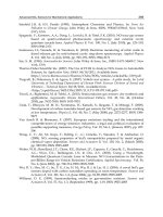
Figure 1 shows an image of superhydrophobic and superhydrophilic plant leaves. The lotus
leaf and the taro leaf show a similar surface morphology with nano patterns on micro
conical structures with a diameter of around 10µm, representing the superhydrophobic
structure. However, the water lily shows only a microstructure having superhydrophilicity
without nanoscale structures. This is very interesting because both the water lily and the
lotus are aquatic plants. However, the water lily leaves are positioned on the water’s
surface, whereas the lotus leaves elevate several feet above it. Therefore, their surfaces are
adapted to an ambient environment very intelligently.
Beyond a Nature-inspired Lotus Surface: Simple Fabrication Approach Part I. Superhydrophobic
and Transparent Biomimetic Glass Part II. Superamphiphobic Web of Nanofibers
147
Fig. 1. Optical and SEM images of plant leaves showing the superhydrophobic and
superhydrophilic characteristics: (a) lotus leaf, (b) taro leaf, and (c) water lily
Part I. Superhydrophobic and transparent biomimetic glass
A combination of colloidal lithography and plasma etching is a good candidate to create
well-ordered micro/nanostructured surfaces easily. In particular, superhydrophobic and
transparent glass can be created using only nanobeads smaller than 100 nm to maintain the
proper level of transparency [22]. Here, a combination of colloidal lithography and plasma
etching is used to fabricate superhydrophobic and transparent glass.
A schematic diagram of the fabrication process is shown in Figure 2. First, quartz glass is
prepared after cleaning it by immersion in an Alconox solution (Sigma, Inc.). A water drop
deposited on the cleaned dry glass surface shows a contact angle of nearly 0° without any
particles of dust. Single layers of polystyrene beads were formed by spin coating as a
colloidal mask. Polystyrene beads (Polysciences, Inc.) with diameters of 100 nm (S.D. = 4%)
were purchased in the form of an aqueous suspension. The polystyrene bead solution was
diluted to 0.6% with a mixture of methanol and triton X-100 to increase its volatility and to
prevent aggregation. Spin-coating of the polystyrene nanosphere solution was performed at
different spin rates for 1 minute and the quartz glass was then etched with a mixture of CF
4
and H
2
gas to enhance the etching selectivity. Finally, chemical coating of the low-surface-
tension composition was done to obtain the superhydrophobic property. Additional
information concerning this experimental method is available in the literature [20].
Figure 3 shows SEM images the spin-coated polystyrene beads created under several
conditions, in the case 1000 rpm, 2000 rpm, 3000 rpm, 4000 rpm, and 5000 rpm, for each
sample. The polystyrene beads do not spread well at a low spin rate i.e., 1000 rpm; whereas
(a) Lotus lea
f
(b) Taro lea
f
(c) Water lil
y
Advances in Biomimetics
148
the beads are better dispersed at a relatively high spin rate i.e., 4000 and 5000 rpm. The
coverage of the nanospheres derives from the balance between the spin rate and the
volatility and viscosity of the colloidal suspension in the shear alignment process [23].
Among several spin rates, 3000 rpm resulted in the best spin-coated polystyrene bead layer.
Fig. 2. Schematic diagram of the fabrication method
Fig. 3. SEM images of polystyrene bead layers spin-coated at different spin rates: 1000, 2000,
3000, 4000, and 5000 rpm
SEM images of polystyrene beads that were spin-coated well are shown in Figure 4. They
have a single layer with close-packed and hexagonally ordered shapes. The polystyrene
bead layers were also formed without defects or multiple polystyrene bead layers at an
optimum spin rate, i.e., 3000 rpm.
However, for the etching process of the glass, the space between the beads of the colloidal
mask requires for a reactive ion treatment on the glass surface. Therefore, spin-coated
polystyrene beads were etched with CF
4
plasma for 30 seconds at a RF plasma power of 100
W to decrease the diameters of the beads. Figure 5 shows SEM images of the formed spacing
Beyond a Nature-inspired Lotus Surface: Simple Fabrication Approach Part I. Superhydrophobic
and Transparent Biomimetic Glass Part II. Superamphiphobic Web of Nanofibers
149
between the colloidal mask beads. An interparticle distances between the beads of around
20 nm was chosen for the glass etching space.
Fig. 4. SEM images of a single layer of polystyrene beads with diameters of 100 nm prepared
by spin-coating at 3000 rpm: (a) an image at 10000X magnification, and (b) an image of
50000X magnification [20]
Fig. 5. SEM images of a reactive ion etching (RIE)-assisted colloidal mask of single-layered
polystyrene beads treated with CF
4
plasma for 30 s; (a) top-view and (b) tilted view at 30º
[20]
The nanostructures on the glass surface were formed by etching with the modified colloidal
mask. Generally, glass surfaces are etched with CF
4
or SF
6
plasma. However, the use of only
CF
4
plasma can lead to etching of the glass surface as well as over-etching of the 100 nm
polystyrene beads, as shown in Figure 6(a). To formulate a nanostructure with a high aspect
ratio, conservation of the polystyrene beads is critical during the etching process. The
addition of H
2
plasma can serve as a solution and thus can protect the polystyrene beads.
Figure 6(b) shows the result of the selective etching of the glass surfaces with a mixture of
CF
4
plasma and H
2
plasma at a ratio of 2:1. Depending on the portion of the H
2
plasma, the
selectivity between the polystyrene colloidal mask and the glass changed. When a greater
amount of H
2
plasma was added, the selectivity of the etching was increased. On the other
hand, the etch rate of the glass was reduced.
(a)
(b)
(a)
(b)
Advances in Biomimetics
150
Fig. 6. SEM images of a nanostructured glass surface etched with (a) CF
4
plasma and (b) a
mixture of CF
4
plasma and H
2
plasma at a ratio of 2:1 for 3 min. The SEM images were
obtained at a tilted view of 30º.
Figure 7 shows the nanostructured glass surfaces according to the etching time with a
mixture of CF
4
plasma and H
2
plasma at a ratio of 2:1. The heights of the nanostructures are
in direct proportional to the etching time. The nanostructures on the glass surface formed a
sharp end on the top and reached a height of nearly 500 nm after 11 minutes of etching. The
etching rate in the given reactive ion etching condition was approximately 40 nm/min.
Fig. 7. SEM images of nanostructures on a glass surface etched with different etching times:
2, 7, 11, 13, and 15 min
A high-magnification image of the fabricated nanostructures is shown in Figure 8. This SEM
image was obtained under environmental SEM conditions of a low pressure and a low
applied voltage of 3 keV without a platinum coating. Compared to the conventional SEM
images, the tower-shaped nanostructures have a sharp end on the top. This suggests that the
actual shape of the nanostructures is slightly different from that shown in the SEM images
when the image is obtained with a metal coating to prevent electron charging on the
insulating surface of the sample. The aspect ratio the glass nanostructure was noted to be
close to 4 after 10 minutes of etching.
As mention in the introduction, two main factors govern the wettability. The important
factor is the chemical property of the surface. When the surface is made up of low surface
energy chemicals, a geometrical surface structure enhances the hydrophobicity [24]. The
geometrical surface structure of a solid is determined by the fractal structure and the
roughness. Therefore, the as-prepared nanostructure glass samples must be modified
chemically to obtain surface hydrophobicity.
Self-assembled monolayers (SAMs) of tridecafluoro-1,1,2,2-tetrahydrooctyltrichlorosilane
(FOTS) were used as the low surface tension chemical. FOTS SAMs were deposited using a
(a) (b)
2 min
7 min 11 min 15 min
13 min
Beyond a Nature-inspired Lotus Surface: Simple Fabrication Approach Part I. Superhydrophobic
and Transparent Biomimetic Glass Part II. Superamphiphobic Web of Nanofibers
151
vapor-deposition method after glass etching and the removal of the remaining polystyrene
beads from the top of the nanostructures. An ash process with 30 seconds of O
2
plasma
following the CF
4
etching process was applied to remove the remaining polystyrene from
the top of the nanostructures. The treated glass samples were then placed in a plastic
container with 100 μL of FOTS droplets. Monolayer-assembled deposition was performed
for 30 minutes at room temperature. The vapor deposited samples were annealed at 80ºC for
1 hour to stabilize the bonding between the glass surface and the FOTS molecules as well as
to increase the well-ordered packing of the FOTS molecules.
Fig. 8. SEM image of glass nanostructures after plasma etching for 10 min. The image was
obtained under environmental SEM conditions without a metal coating.
Figure 9 shows the water contact angles of the nanostructured glass surfaces before and
after the low-surface-tension chemical treatment. The wettability of the surfaces was
measured with a contact angle analyzer (Phoenix 300, SEO Inc.) with deionized water
droplets of 10 μL in volume. The water contact angle of the nanostructured glass surface
was close to 4º (Figure 9(a)). The nanostructures on the surface enhanced the hydrophilicity
depending on the nature of the flat glass surface. However, the nanostructured surfaces
with the FOTS SAMs coating showed superhydrophobicity, with a water contact angle of
nearly 150° (Figure 9(b)). Figure 9(c) clearly shows the superhydrophobicity of the fabricated
glass. This superhydrophobic glass surface also shows a hexadecane contact angle of 110°
given a volume of 10 μL. In the relationship between the superhydrophobic property and
the height of the nanostructure, the contact angle of both the water and hexadecane
increased steadily as the height of the nanostructure increased to an aspect ratio of 2.5.
In the fabrication of superhydrophobic glass, an important requirement is to retain the
transparency of the glass. Therefore, only the use of a nanostructure smaller than the visible
wavelength of light can enhance the wettability without leading to opacity. The
transmittance of the superhydrophobic glass surface with a nanostructure diameter of 100
nm and different heights in the range of 50 nm to 1000 nm was investigated by UV-Visible
spectrometry. Figure 10(a) shows the UV-Visible spectra of the nanostructured glasses with
the FOTS SAMs coating and the bare quartz glass as a reference. In the range of the visible
wavelength of 400 nm to 700 nm, it was determined that the antireflective phenomena
known as the moth-eye antireflection effect existed. A decrease in the transmittance to less
Advances in Biomimetics
152
than the 500 nm wavelength was detected in several samples having a relatively high
height. This may have originated from the scattering of the light given the high height of the
nanostructures. However, the overall transmittance increases due to the decrease in the
reflection on the nanostructured glass surface. Finally, a superhydrophobic and
antireflective glass having a well-ordered nanostructure was demonstrated, as shown in
Figure 10(b).
Fig. 9. Images of the water contact angles for (a) a nanostructured glass surface and (b) a
nanostructured glass surface after the FOTS SAMs coating. The water contact angles are 4º
and 150°, respectively [20]. (c) Sequential images of water droplets falling onto the
nanostructured glass surface after the FOTS SAMs coating. The aspect ratio of the
nanostructure is 4.
Fig 10. (a) 5 nanostructured and hydrophobic coated glasses with the different etching time
and bare sample, and (b) an image of water on the superhydrophobic nanostructured glass [20]
(a)
(b)
(b)
(a)
(c)
Beyond a Nature-inspired Lotus Surface: Simple Fabrication Approach Part I. Superhydrophobic
and Transparent Biomimetic Glass Part II. Superamphiphobic Web of Nanofibers
153
Part II. Superamphiphobic web of Nanofibers
Currently, many researchers are interested in the demonstration of multifunctional surfaces
having dual properties such as a superhydrophobicity and antireflective surface, an
antifogging and antireflective surface, a switchable surface, a repellent surface capable of
repelling several types of liquids, and others. Particularly, surfaces that repel water and
organic liquids have recently received a great deal of attention from research and industry
fields. Several important findings pertaining to amphiphobic surfaces have been reported
with regard to the design of surfaces [18,19].
Two factors should be also considered in the design of a superamphiphobic surface: the
chemical composition and structural morphology. For organic liquids, it is impossible to
find a chemical layer that yields a contact angle greater than 90° on a flat surface [25,26].
Thus, a structural morphology must be created in which the surface curvature exhibits
extreme surface resistance to wetting from all liquids. It is known that the entrapment of air
beneath a re-entrant structure prevents the transition from a nonwetted state to a wetted
state, even for liquids with low surface tension [27-29].
Of all the re-entrant structures, webs of microfibers and nanofibers are good candidates for a
superamphiphobic surface because an electrospinning method can easily produce microfibers
and nanofibers from a variety of polymeric materials [30]. In addition, the diameter of the
fibers and the gap distance between the electrospun fibers can be controlled according to the
processing parameters, such as the solvent, viscosity, surface tension, and electrical
conductivity. Therefore, to obtain the information on robustness against wetting from low
surface tension liquids, microfibers and nanofibers can form a various superamphiphobic
surface. Here, an electrospun web of poly(2,2,2-trifluoroethyl methacrylate) (PTFEMA) fibers
is studied to obtain an understanding of a superamphiphobic surface. The morphology of this
web is modulated by changing the polymer solution concentration with other fixed processing
conditions. That is, we used an applied voltage of 20 kV, a distance of 20 cm between the
syringe needle tip and the collector, and a flow rate of 0.2 mL/h. A detailed description of the
experimental method was introduced in earlier research, including the synthesis and
electrospinning conditions of the PTFEMA as well as the characterization methods of the
electrospun nanofibers web [21, 31].
A remarkable feature is that the fabrication of a web of superamphiphobic fibers was
performed using a conventional electrospinning process of fluorinated polymers without
any additional functionalization. A PTFEMA solution can be electrospun well with
conventional processing parameters, as synthesized PTFEMA dissolves homogeneously and
easily in several solvents, including Dimethyl foramide (DMF), which is an adequate solvent
for electrospinning. To investigate the wetting property of the web, first the surface chemical
compositions of the PTFEMA web were analyzed by XPS. An electrospun electrospun and
solution casted PTFEMA sample were prepared prepared from a 26 wt% solution of DMF.
The fluorine content (F/C ratio) was outstandingly high, at 0.57, and the water contact angle
was 153° for the elecrospun sample, whereas the solution casting PTFEMA film showed an
F/C ratio of 0.40 and a water contact angle of only 89°. The enrichment of the fluorocarbon
composition and the water contact angle of the electrospun PTFEMA were caused by the
surface segregation, the high ratio of the surface area to the volume, and by the rough
surface morphology [32].
Figure 11 shows the superamphiphobicity of the electrospun nanofiber web. The web of
PTFEMA repels both types of liquids shown in the figure, one with a surface tension of 72.8
mN/m (water colored with blue ink) and the other with a surface tension of 27.8 mN/m
(hexadecane colored with red ink), while exhibiting contact angles greater than 150°.
Advances in Biomimetics
154
Fig. 11. Photograph of 6 μL droplets of hexadecane (colored with red ink) and 6 μL droplets
of water (colored with blue ink) on an electrospun web of PTFEMA fibers with a 26 wt%
polymer solution concentration concentration [21]
All of the electrospun webs of PTFEMA fiber are typical superhydrophobic surfaces,
showing water contact angles that exceed 150°. However, the wetting response of the low
surface tension liquid hexadecane differed depending on the morphology of the fiber webs.
The sample prepared from the 26 wt% solution had the thinnest fiber diameter of
approximately 500 nm and the narrowest diameter distribution, ranging from 300 nm to 700
nm; its surface repels hexadecane with a high contact angle of around 154°, as shown in
Figure 12(a). However, Figure 12(b) shows that the fiber web electrospun with a 24 wt%
concentration is different in terms of the fiber diameter and hexadecane contact angle. The
24 wt% sample had an average diameter of 600 nm and considerable variation in its fiber
diameters, with some very thick fiber diameters of around 2000 nm or 3000 nm. In addition,
the hexadecane droplet collapses with a contact angle of approximately 25° despite the fact
that its surface exhibits superhydrophobicity.
The interaction between hexadecane and a web of PTFEMA fiber was investigated to
confirm the wetting property of the 24 wt% samples. We obtained SEM images to determine
how the morphology of the web changes after soaking the fiber web with hexadecane. As
shown in Figure 13, an appreciable change was not detected after the soaking test, which
proves that PTFEMA does not react with or dissolve in hexadecane.
The robustness parameter was studied to elucidate the wetting and nonwetting phenomena
of hexadecane on superhydrophobic nanofiber webs with different fiber diameters. We used
the robustness equation developed by Tuteja and Choi to reveal the relationships among the
robustness, the fiber diameter, and the degree of porosity [19]. A detailed explanation of the
robustness of fiber web samples is available in the literature [21]. The calculated robustness
shows how the hexadecane droplet is sustained on the 26 wt% sample and why it collapses
on the 24 wt% sample.
Figure 14 shows a summary of the hexadecane robustness and contact angle in relation to
the gap distance and fiber radius depending the PTFEMA solution concentration. When the
Beyond a Nature-inspired Lotus Surface: Simple Fabrication Approach Part I. Superhydrophobic
and Transparent Biomimetic Glass Part II. Superamphiphobic Web of Nanofibers
155
apparent contact area is identical, a thinner fiber and lower porosity increase the robustness.
The 24 wt% sample shows low robustness, explaining why the hexadecane droplet
collapsed although it had a high water contact angle. The 26 wt% sample had the highest
level of robustness, keeping the hexadecane droplet intact for more than 8 hours. Figure 14
suggests that the 28 wt% sample and the 30 wt% sample repel the hexadecane droplet for
quite a long time. The assumption that the diameter and gap distance of the fibers on the
nanofiber surface are homogeneous in terms of the robustness equation implies that the 24
wt% sample has a relatively high level of robustness. However, local variation in both the
fiber diameter and the distribution in our samples caused local weak spots to arise with a
Fig. 12. Hexadecane and water contact angle images, SEM images, and schematic diagram of
a nanofiber web with a hexadecane droplet. PTFEMA fibers were electrospun with different
polymer solution concentrations: (a) 24 wt% and (b) 26 wt%. The volume of both the
hexadecane and the water was 6 μL [21].
Fig. 13. SEM images of PTFEMA fibers electrospun from 24 wt% after soaking with
hexadecane: (a) 5000X magnification, and (b) 20000X magnification
(a)
(b)
(a)
(b)