Advances in Mechatronics Part 5 pot
Bạn đang xem bản rút gọn của tài liệu. Xem và tải ngay bản đầy đủ của tài liệu tại đây (1.48 MB, 20 trang )
4
Mechatronic Systems for Kinetic
Energy Recovery at the Braking
of Motor Vehicles
Corneliu Cristescu
1
, Petrin Drumea
1
, Dragos Ion Guta
1
,
Catalin Dumitrescu
1
and Constantin Chirita
2
1
Hydraulics and Pneumatics Research Institute, INOE 2000-IHP, Bucharest
2
“Gheorghe Asachi” Technical University, Iasi
Romania
1. Introduction
Vehicle manufacturers are continually concerned with reducing fuel consumption and
lowering polluting emissions. (Gauchia & Sanz, 2010). Besides the vehicles which use
liquefied gas, methanol, electricity or fuel cells, also, there have been designed and
manufactured diferent hybrid propulsion motor vehicles. (Toyota, 2008; Permo Drive, 2009;
Eaton, 2011).
It is known that during a work cycle of a motor vehicle, which consists of a period of
acceleration, another one of running at constant speed and a period of deceleration, the
power required during acceleration is much greater than that required while running at
constant speed and, in principle, it is this power what determines the size of engine installed
on the motor vehicle. Upon vehicle braking, kinetic energy acquired by acceleration of the
motor vehicle is converted into heat energy, which is located in the braking system and gets
lost, irreversibly, into space, with negative effects on global warming. So, rightfully, there has
been formulated the technical problem that, during the motor vehicle braking stage, the
kinetic energy gained by it to be recovered and stored in power batteries and then used
during start-up and acceleration stages. Therefore, vehicle manufacturers consider that one
of radical solutions in order to achieve the above mentioned goals is a deep change of motor
vehicle propulsion method, promoting hybrid propulsion systems, which are considered to be
solutions for the near future, for a substantial decrease of fuel consumption and polluting
emissions. Propulsion systems that are composed of, besides a conventional propulsion
system with an internal combustion engine, at least another one based on another type of
energy, capable of providing torque/traction moment at the motor vehicle wheels, form a
hybrid propulsion system. If they, along with propulsion, can recover, during braking stage,
part of the kinetic energy accumulated in the acceleration stages, and then they are called
hybrid regenerative systems. A feature of regenerative hybrid vehicles is that they include
components that capture and store kinetic energy of the vehicle during braking process, for it
to be used later, or when accelerating or at constant speed movement. Systems for capturing
and storing kinetic energy perform its converting and storing under different forms of
energy, namely: as mechanical/ kinetic energy of a flywheel, as potential energy of a
Advances in Mechatronics
70
working fluid (liquid or gas), as electrochemical energy (Gauchia & Sanz, 2010)), or as
electrostatic energy. To restore the recovered and stored energy, drive/propulsion systems
are, also, of several types, namely: hydro-mechanical systems (hydrostatic or
hydrodynamic), electromechanical systems (direct current or alternating current) and
mechanical systems (mechanical or mechanic-inertial). Worldwide, various solutions have
been designed for developing hybrid systems, but most common are hybrid systems with
thermo-electric drive and hybrid systems with thermo-hydraulic drive. A special
competition is under development between the thermo-electric hybrid system, (Toyota, 2011;
Eaton, 2011), which, in addition to the heat engine, also has an electric propulsion system,
and the thermo-hydraulic hybrid system, (Permo-Drive, 2011; Eaton, 2011a; Bosch Rexroth,
2011), which, in addition to the driving heat engine, has a hydraulic propulsion system.
Compared with electric vehicles, characterized by a reduced autonomy of movement, hybrid
vehicles have many advantages, Usually, the kinetic energy of the motor vehicle, accumulated
in the accelerating phase, in the braking phase is converted in the thermal energy which is,
normally and irremediable, wasted in atmosphere. Therefore, the main objectives of the
hybrid systems are the recovering kinetic energy of the road motor vehicles and reducing the
fuel consumption and the environment pollution (Parker Hannefin, 2010).
From the above presented issues, it is clear that hybrid propulsion systems are very complex
systems, multidisciplinary and interdisciplinary. Also, they develop dynamic/transient
operation modes, with rapid succession of events over time, difficult to drive and control
with conventional means. Therefore, for such complex systems, the only technology able to
manage, optimize and control in conditions of total safety, is mechatronics technology, for
which reason hybrid propulsion systems represents a new field of application of mechatronics
(Ardeleanu & al.; Cristescu et al., 2008b; 2007; Maties, 1998).
2. The mechatronic system for kinetic energy recovery at the braking of
motor vehicles
Basic solution, adopted to achieve the kinetic energy recovery system for the braking stage,
was that of kinetic energy recovery by hydraulic means, based on the use of a hydraulic
machine which can operate both as a pump, during braking, and as an motor, during
acceleration/start-up. In the braking stages, the mechanical/kinetic energy of the motor
vehicle is converted by the hydraulic machine, which is working as a pump, into
hydraulic/hydrostatic energy and stored at high pressure, in hydro-pneumatic
accumulators. In the acceleration/start-up stages, hydrostatic energy, stored in hydro-
pneumatic accumulators, is converted back into mechanical energy by the hydraulic machine,
which is working now as a motor and generating acceleration of the motor vehicle,
(Cristescu, 2008a).
The aim of the designed hydraulic system is the recovery of kinetic energy, in the braking
stage of a motor vehicle.
The technical problem, which is solved by the energy recovery hydraulic system, is the
capturing and storing of the lost energy in the braking stages at medium and heavy motor
vehicles.
The method consists in using one mechanic and hydraulic module, which is able to capture
and convert the kinetic energy into hydrostatic energy and, also, storage and reuse it for
acceleration and start-up of the road motor vehicles.
Mechatronic Systems for Kinetic Energy Recovery at the Braking of Motor Vehicles
71
The implementation of a hydraulic system for recovery of kinetic energy, on a motor
vehicle, transforms it into a hybrid motor vehicle and leads to decreasing of the fuel
consumption and, also, to reducing of the environmental pollution.
The main objectives of the hybrid propulsion systems are the recovery of kinetic energy of the road
motor vehicles, in order to reduce the fuel consumption and to increase the energy efficiency
of the propulsion systems of the motor vehicles.
2.1 Conceptual model and mechatronic configuration of the kinetic energy recovery
system
2.1.1 Constructive configuration and implementation of the energy recovery system
on motor vehicles
Constructive and functional concept of developing and implementing a system for braking
energy recovery is shown, in schematically, in Figure 1, which presents a conceptual model
of construction and installation/implementation of the kinetic energy recovery system on a
motor vehicle. The energy recovery system consists, in essence, of a hydro-mechanical
module which includes a variable displacement hydraulic machine, that can operate both in
pump mode, during braking, and in motor regime, during start-up/acceleration of the
motor vehicle. The hydraulic machine is driven by a mechanical transmission and is
controlled by an electric and electronic control subsystem, which performs, also, the
interfacing with the braking and acceleration systems of the basic motor vehicle, operation
being controlled through a processor, which provides the information support, specific to
mechatronic systems.
Fig. 1. A conceptual model of construction and installation/implementation of the recovery
system on motor vehicles.
Implementation/installation of the energy recovery system can be done on motor vehicles
that have a long cardan axle between the gearbox CV and the differential mechanism DIF,
by replacing it with two shorter axles. Mechanical connection between the cardan axles Ac1
and Ac2 and the recovery system R-A is permanent and is achieved through a mechanical
transmission, which adapts the rotational speed of the cardan axle to the operating
rotational speed of the hydraulic machine/unit UH in the system. Depending on the specific
conditions provided by the motor vehicle on which the recovery system is installed, the
coupling outlet and mechanical transmission can be placed at the end of the cardan axle Ac1
close to the gearbox, at the end of the cardan axle close to the rear drivetrain TR, or between
the gearbox CV and the drivetrain TR, by splitting the cardan axle.
Advances in Mechatronics
72
Hydraulic unit is a hydraulic machine with variable displacement/geometric volume, which
can vary between 0 and a maximum value (V
g
=max). Axial piston hydraulic unit can be
removed from the zero displacement position, only when the vehicle goes forward. When it
goes into reverse, the displacement of the unit remains zero (Vg = 0).
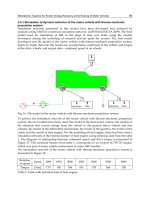
Basic schematic diagram of the automatic adjustment system of the motor vehicle hybrid
propulsion system, that includes an energy recovery system, is shown in Figure 2. The
adjustment system achieves proportionality between the the stroke of the brake pedal,
respectively, the stroke of the acceleration pedal, on slowing down, respectively, on starting-
up the motor vehicle.
Fig. 2. Automatic adjustment schematic diagram of the hybrid propulsion system of motor
vehicles.
According to the adjustment schematic diagram in Figure 2, component elements of the
system are the next ones:
EI - the input element, which converts the input parameter of the system, that is the angular
stroke of brake pedal
f
, respectively angular stroke of acceleration pedal
a
, into the
preset parameter
p
a , that is the deceleration, respectively, acceleration, according to the
operation stage, braking or acceleration;
EC - the comparison element, which compares the preset parameter
p
a with the measured
acceleration
m
a and transmits to the automatic regulator RA the discrepancy
between the
two parameters, in order to operate correction;
RA - the automatic regulator, which determines, depending on the error
, the value of the
drive parameter
c,, that will work to equalize the preset acceleration
p
a with the actual
acceleration value
a
;
EE - execution element, represented by the axial piston hydraulic unit, which determines the
value of vehicle acceleration proportional to the received command; this item plays a double
part: information and power circulation.
Recovery system also comprises the hydraulic devices to achieve hydraulic circuits, as well
as the transducers required for monitoring and automatization of braking and start-
up/acceleration processes.
According to the theory of automatic systems, the global systemic model is shown in
Figure 3.
Mechatronic Systems for Kinetic Energy Recovery at the Braking of Motor Vehicles
73
Fig. 3. Global systemic model of a motor vehicle equipped with a kinetic energy recovery
system.
During the braking stage, the recovery system ERS captures, from the drivetrain VDR, the
vehicle's kinetic energy (with mechanical parameters: torque/moment
M and rotational
speed n), converts it into hydrostatic energy (with hydraulic parameters: pressure p and
flow Q) and stores it inside the storage subsystem ESS. During the start-up stage, the
hydrostatic energy (with hydraulic parameters: pressure
p and flow Q) is transmitted to the
recovery system ERS which converts it into mechanical energy (with mechanical
parameters: torque
M and rotational speed n), and uses it to add torque/moment to the
propulsion and drivetrain of the vehicle, for acceleration or start-up, as appropriate.
The general systemic model of interfacing and interconditioning of the energy recovery
system with the systems, that command and control motor vehicle movement (braking and
acceleration systems), is shown roughly in Figure 4.
Fig. 4. General systemic model of the command and control system.
As it is shown in Figure 4, the microprocessor MP manages all data of the whole hybrid
vehicle, making its operation optimal during the two stages, braking and acceleration. The
microprocessor receives information on the braking or acceleration command, rotational
speed of drivetrain, pressure inside the storage system, and manages the entire process
through commands sent to the energy recovery system and to the conventional braking or
acceleration systems.
2.1.2 Mechatronics structure of the kinetic energy recovery system
As one can see in Figure 5, mechatronic model of kinetic energy recovery system in motor
vehicle braking has a typical mechatronics structure, see (Maties, 1998; Cristescu et al.,
2008b), consisting of the next four main subsystems:
-
mechanical-hydraulic subsystem, which consists of hydro-mechanical module, hydraulic
station, battery of hydro pneumatic accumulators and hydraulic commands pump,
installed on a special transmission of the heat engine;
Advances in Mechatronics
74
- electronic drive and control subsystem, which consists of all electric, electronic and
automation elements and components which ensure system operation, including the
drive and control panel;
-
subsystem of sensors-transducers, which consists of all necessary sensors and transducers
that provide capturing of evolution over time, of process parameters and conversion
into electric parameters, easily processable by the system;
-
computer subsystem for process control, consisting of user licensed purchased software or
software specifically designed and dedicated to the proper functioning and
performance of the system, and also the related processor or computer.
Fig. 5. Mechatronics model of energy recovery system at the braking of motor vehicles.
This structure defines and substantiates the
mechatronic conception of developing the
recovery system. Mechatronic system for recovery of braking energy at motor vehicles
operates based on dedicated software, which monitors the system and enables registration
of the output parameters and control of the main parameters of the system.
In addition to the specific subsystems of a energy recovery system, mentioned above,
mechatronic system monitors and controls, through special interface components, some
other subsystems of the basic motor vehicle, on which implementation has been performed,
namely: subsystem for interfacing with the classic acceleration subsystem of the motor
vehicle and subsystem for interfacing with the classic braking subsystem of the motor
vehicle. The energy recovery system is conducted by a computer with specialized software.
Mechatronic Systems for Kinetic Energy Recovery at the Braking of Motor Vehicles
75
2.2 Presentation of the thermo-hydraulic propulsion system
Further on, there is presented a Romanian technical solution for a hybrid propulsion system
that has been obtained by implementation of an energy recovery hydraulic system on a
medium motor vehicle, which has, already, an existing thermo-mechanical propulsion
system. In this maner, the mounting of the hydraulic recovery system, on the motor vehicle
with thermo-mechanical propulsion system, leads to transformation of the vehicle into a
thermo-hydraulic hybrid vehicle. Entire hybrid propulsion system has been conceived as a
mechatronic system, see (Cristescu, 2008a).
2.2.1 The conceptual model of the thermo-hydraulic hybrid vehicle
In Figure 6 is presented the conceptual model of the Romanian technical solution for a
hybrid propulsion vehicle, which consists in a energy recovery hydraulic system that has
been implemented on a medium motor vehicle.
The
conceptual model illustrates a thermo-hydraulic parallel hybrid motor vehicle, as the
energy recovery hydraulic system implemented does not interrupt the thermo-mechanical
direct driveline to the motor vehicle wheels.
This hybrid vehicle has resulted after the implementation of kinetic energy recovery system
with hydraulic drive on the vehicle type
ARO-243, with thermo-mechanical propulsion.
Basic motor vehicle allows discontinuity of the thermo-mechanical driveline of the rear
bridge, by removing the appropriate cardan axle, thermo-mechanical drive remaining only
on the fore bridge, which is exactly the
thermo-mechanical propulsion subsystem of the
vehicle. By mounting the energy recovery hydraulic system on the rear bridge of the vehicle,
there is created a second drive subsystem namely the
mechanical-hydraulic subsystem that
drives the rear bridge; thus there is made a parallel hybrid thermo-hydraulic propulsion system
of the motor vehicle, these subsystems being able to propel either separately or together,
(Cristescu, 2008a).
Fig. 6. The conceptual model of the thermo-hydraulic hybrid vehicle with energy recovery
hydraulic system.
The recovery hydraulic system of kinetic energy has been designed to be implemented on a
Romanian automotive, well-known as ARO 243 type, which has a 4x4 driving system. In the
Advances in Mechatronics
76
conceptual model of the hybrid propulsion vehicle, presented in Figure 6, can be
distinguished the Diesel engine MD, the gearbox CV and the gear transmission to the front
wheels, through one torque transducer (TMR) and one cardan axle. There can be seen the
mechanical transmission to the hydraulic machine/unit UH, the tank for low pressure LT
and the storing system for height pressure, which consists of the two hydraulic and
pneumatic accumulators AC1 and AC2. The hydraulic power is transmitted, to the breech
wheels, through the torque and rotation transducer (TMR) and a cardan axle. The hydraulic
machine can be connected, in parallel, anywhere in the driveline, but, generally, it is
mounted between the gearbox and differential mechanism. The main part of the recovery
system is the hydraulic machine with variable geometrical volume, that can work both as a
pump, in the braking process, and, also, as a hydraulic motor, in the start-up process of the
motor vehicle.
The hydraulic machine is driven through a gearbox transmission, being assisted by an
electro-hydraulic system, which is interfaced with the subsystems for braking and
acceleration of the vehicle, all controlled by a processor. Operation of the recovery system
has a lot of sensors and transducers, for monitoring and controlling the evolution of
parameters.
The hybrid propulsion system, which contains the energy recovery hydraulic system, has
been developed in a
mechatronic conception (Maties, 1998). The system contains:
mechanical and hydraulic subsystem, drive and control electronic subsystem and the data
management informatic subsystem. The interface of the first two subsystems is the
subsystem of sensors and transducers, which provides information on the evolution of the
main parameters of the kinetic energy recovery mechatronic system. The sensors and
transducers subsystem allows data acquisition from the torque, temperature, flow and
pressure transducers (Calinoiu, 2009). The mechatronic system is working on basis of
dedicated software, which allows monitoring and recording the evolution of output and
control parameters of the system. This component defines the mechatronics basis for the
system design and development.
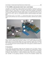
2.2.2 The main physical modules of the energy recovery hydraulic system
In essence, by mounting of the kinetic energy recovery system, Figure 7, on the motor
vehicle
ARO-243, presented in Figure 7(a) and Figure 7(b), transforms it in a hybrid motor
vehicle
, which have now, besides of the existing thermo-mechanic propulsion subsystem, an
supplementary propulsion system, named hydro-mechanic propulsion subsystem.
The main parts/subassemblies of the kinetic energy recovery mechatronic system are:
-
hydro-mechanical module, Figure 7(c) , is composed of a chain transmission, equipped
with a torque and rotation transducer TMR, and a hydraulic unit/machine UH, serving
as a pump, during braking, and as an motor, during start-up. The hydraulic machine is
a variable-displacement one, manufactured by the company
Bosch Rexroth Group (Bosch
Rexroth Group, 2010), where flow control is performed electronically, through an
automatic control closed loop;
-
hydraulic station SH itself, Figure 7(d), represents the subassembly connecting the hydro-
mechanical transmission and the hydro pneumatic accumulators battery, where
hydrostatic energy is stored. Hydraulic station consists of oil tank with its specific
elements, and of hydraulic blocks with equipment necessary to perform the
functions;
Mechatronic Systems for Kinetic Energy Recovery at the Braking of Motor Vehicles
77
(a) The motor vehicle ARO-243(lateral view) (b) The motor vehicle ARO-243(behind view)
(c) The hydro-mechanical module (d) The hydraulic station
(e) The accumulators battery (f) Installation of the pump command
(g) Electronic drive and control subsystem (h) Informatics subsystem
Fig. 7. The main parts/subassemblies of the kinetic energy recovery mechatronic system.
Advances in Mechatronics
78
- hydro pneumatic accumulators battery, Figure 7(e), is a unit consisting of two hydro
pneumatic accumulators, enabling hydrostatic energy storage, during braking stage,
and supply of hydraulic motor with potential hydrostatic energy, during start-up or
acceleration of the motor vehicle;
-
pump command, Figure 7(f), is mounted to the power outlet of the heat engine and serves
to hydraulically drive the hydraulic machine and unlockable valves for hydrostatic
power supply of hydraulic machine.
In addition to the presented subsystems, the system has, also, an electronic drive and control
subsystem, Figure 7 (e), and an
informatics management subsystem, Figure 7 f), all designed
and developed in a unitary mechatronic conception.
2.3 Some theoretical results obtained by mathematical modeling and numerical
simulation
Motor vehicle dynamic behavior is determined by the size, direction and way of forces
acting on it. They are classified into two broad categories: active forces or
traction forces,
which cause motor vehicle movement, and resistance forces, which oppose its movement.
Resistant forces are given by the resistance to running on the road, the resistance of air to
movement, additional resistance opposed to running on a ramp, as well as inertial forces
that appear on accelerating or stoping a motor vehicle. To overcome these resistance forces,
energy consumed to propel the motor vehicle fall into:
-
irreversible consumed energy, for overcoming all resistance to forward (rolling,
aerodynamics, losses in transmission) and which are due, first, to internal and external
friction of the motor vehicle;
-
recoverable energy, used for accelerating or climbing a ramp, in this case the kinetic
energy and potential energy, which can be recovered. This recoverable energy can be
partially accumulated, instead of being dissipated through braking system, if the motor
vehicle is equipped with energy recovery, storage and reuse system.
Therefore, as a first step, preliminary theoretical research has been conducted, based on
mathematical modeling and numerical simulation, in order to know the dynamic behavior
of motor vehicle
ARO 243, intended to be equipped with a hydraulic system for kinetic
energy recovery at braking. For mathematical modeling and computer simulation of
dynamic behavior of experimental motor vehicle there have been used mathematical
relations in the specialized literature and
MATLAB with Simulink software package, (The
Math Works Inc., 2007), which is dedicated to numerical calculation and graphics in science
and engineering. Some theoretical results obtained are presented below.
2.3.1 Dynamic behavior of the motor vehicle with thermo-mechanic propulsion
system
To model the start-up of the motor vehicle
ARO 243 with thermo-mechanical propulsion
system, when propulsion is provided exclusively by a 48 kW Diesel heat engine, there has
been conducted, first, mathematical modeling and developed a sub-software for simulation
of the external feature of heat engine, i.e. of variation diagram of moment/torque
Me and
engine power
Pe, depending on engine rotational speed n
mot
. This simulation sub-software
will be included, as a subroutine, in the general software for simulation of starting the heat
propulsion motor vehicle. After numerical simulation, using the data about the engine, we
obtained the diagram in Figure 8.
Mechatronic Systems for Kinetic Energy Recovery at the Braking of Motor Vehicles
79
Fig. 8. External feature of a 48 kW Diesel engine.
Mathematical modeling of motor vehicle start-up stage is performed on the basis of relations
known in specialized literature, which are based on the principle of
D'Alembert, according to
which equation of movement is written as:
aa
R
Gdv
FF
gdt
, (1)
where: v
a
is the motor vehicle velocity; G
a
is the motor vehicle total weight; g is gravitational
acceleration;
F
R
is the traction force at drive wheels, and F
is the sum of resistances to
advance that do not depend on acceleration. Coefficient
δ is the inertial coefficient of
rotating masses, which takes into consideration their influence on motor vehicle movement,
with values in the range 1.2 ÷ 1.4, for speed step I, see (Untaru et al., 1974).
It can be written that the sum of resistance forces is given by the next relation:
2
cos sin
aa
FGf KSv
(2)
where:
f is the coefficient of resistence to running; α is the ramp angle; K is the aerodynamics
resistance coefficient; and
S is the frontal surface of motor vehicle. With this notations, the
equation becomes:
2
aa
f cos -G sin - K S v
a
Ra
a
g
dv
FG
dt G
(3)
If it is considered that the movement is done in a horizontal plane, and starting of the motor
vehicle is done at low velocity, equation can be simplified more. Based on the relationship
known in classical literature, there has been developed a complete mathematical model for
the starting-up stage and, based on this one, there has been developed a numerical
simulation software, which allowed, based on structural and functional features of the
vehicle, to obtain some theoretical results of interest in the dynamic evolution of the motor
vehicle. Some of these preliminary theoretical results are shown in the figures below. Thus,
Advances in Mechatronics
80
Figure 9 shows the variation of kinematics parameters and traction force at the wheels of the
investigated motor vehicle. The variation of stroke on start-up is shown in Figure 9(a) and
the variation of velocity on start-up in Figure 9(b). The variation of acceleration on start-up it
can see in Figure 9(c) and the variation of traction force at the wheel is done in Figure 9(d).
(a) Variation of stroke on start-up
(b) Variation of velocity on start-up
(c) Variation of acceleration on start-up
(d) Variation of traction force at the wheel
Fig. 9. Variation of kinematics parameters and traction force at wheels on thermal starting of
the motor vehicle.
2.3.2 Dynamic behavior of the motor vehicle with hydro-mechanic propulsion system
As mentioned above, through implementation, on the motor vehicle ARO 243, of the
hydraulic system for the recovery of kinetic energy during braking, it became a
parallel
thermal-hydraulic hybrid motor vehicle,
which can be powered exclusively by the heat engine,
analyzed in section 2.3.1, exclusively by hydraulic means, which will be studied in this
subchapter, or combined, using both sources of power, being a
hybrid propulsion system. To
concretize the way of transmission of energy flow and to highlight the main subsystems
participating in the starting process, there has been developed a conceptual model of the
hydro-mechanic system, shown in Figure 10. At this stage, it was envisaged that the flow of
hydrostatic energy comes from the hydro pneumatic accumulators, where it is stored for
reuse, through the hydraulic station of the system, reaching the hydraulic machine which,
operating as a hydro motor, converts the hydrostatic energy into mechanical energy and
Mechatronic Systems for Kinetic Energy Recovery at the Braking of Motor Vehicles
81
directs it, by means of the cardan axle and differential mechanism, towards the rear axle to
drive wheels of the motor vehicle.
Fig. 10. A conceptual model of the hydro-mechanic starting system of the motor vehicle.
The sstudy upon the dynamic behavior of the motor vehicle equipped with hydraulic
system for energy recovery, during starting, propelled, exclusively, by a hydraulic system,
also, has been achieved through mathematical modeling and numerical simulation, and it
has enabled knowledge of evolution of the main kinematic and dynamic parameters of the
motor vehicle. Mathematical modeling of the motor vehicle powered exclusively by
hydrostatic energy, supplied by hydro pneumatic accumulators, started from the known
equation of motion of the motor vehicle, but, first, there was necessary mathematical
modeling of the
polytrope decompression process of azote inside the accumulators, Figure 11,
to assess/evaluate the variation of pressure of the oil that actuates the hydraulic motor, see
(Cristescu, 2008).
Fig. 11. Polytrope transformation of azote between the initial state 1 and final state 2 during
the starting process.
Advances in Mechatronics
82
In the assumption that there is no loss of fluid along the hydraulic circuits and the liquid is
incompressible, and if it is marked with
θ
MH
rotation angle of the hydraulic motor shaft and
with
ω
MH
its angular velocity of rotation, then it is obtained the pressure variation law for
the oil inside the accumulators, according to the relation (4). With the relations known in
classical literature (Untaru et al., 1974), there has been developed a mathematical model for
the hydraulic starting-up stage and, after mathematical modeling and numerical simulation,
have been obtained the variations of main parameters of dynamic behavior of the motor
vehicle with hydraulic propulsion, presented in Figure 12.
(a) Variation of oil and gas volumes (b) Variation of pressure inside the accumulators
(c) Variation of start-up stroke (d) Variation of power of HM
Mechatronic Systems for Kinetic Energy Recovery at the Braking of Motor Vehicles
83
(e) Variation of start-up velocity (f) Variation of kinetic energy of the motor vehicle
(g) Variation of acceleration on start-up (h) Variation of energy efficiency
Fig. 12. Variation of the main parameters of hydraulic starting process of a motor vehicle.
In the Figures 12, there are presented some theoretical results of interest regarding the
dynamic behavior of the motor vehicle at its hydraulic start-up. Thus, the variation of oil
and gas volumes are shown in Figure 12(a), where it can see that the oil volume is in
decreasing and the gas volume is in continuous increasing. The pressure in the
accumulators is in continuous decreasing, as see in Figure 12(b). The variation of start-up
stroke is shown in Figure 12(c). The Figure 12(d) highlights the existing of a maximum value
of the power at e hydraulic motor (HM). The variation of start-up velocity is done in Figure
12(e) and this corresponds with the variation of kinetic energy of the motor vehicle, which is
shown in Figure 12(f). The variation of acceleration on start-up of the vehicle is presented in
Figure 12(g). The variation of energy efficiency of hydraulic propulsion is shown in Figure
12(h) and is around of 60%. The pressure variation in accumulators is done by the next
relation (4):
Advances in Mechatronics
84
00
1
1
0
0
10
10
2
2
ac
x
n
n
g
MH
g
MH
pp
pp
V
p
V
p
t
pV
pV
(4)
In the above relation, state 0 is the state of preloading the battery with azotes, characterized
by azotes loading pressure p
0
and their maximum volume V
0
. State 1 is the initial state of the
decompression process, characterized by the maximum pressure p
1
and minimum volume of
gas V
1,
, and state 2 is the final state of the start-up process, when the minimum
allowable pressure p
2
is reached and, also, the minimum volume of gas V
2
. Based on this
relation and on those known from the technical literature (Calinoiu et al., 1998)) there has
been developed a mathematical model and a numerical simulation software in MATLAB
with Simulink graphical environment, (The Math Works Inc., 2007), which allowed to obtain
graphs of variations of the main parameters of interest, describing the dynamic behavior of
the motor vehicle propelled exclusively by a hydraulic system.
2.3.3 Dynamic behavior of the motor vehicle at braking with kinetic energy recovery
To know the dynamic behavior of the hybrid motor vehicle, during braking with recovery of
the kinetic energy available/accumulated at the beginning/before of the braking, there is
made the assumption that, in this stage, the heat engine is operating at ralanty rotational
speed and is disconnected from the transmission, being precluded the use of engine braking.
Assuming the above, all available kinetic energy is taken by the running system and sent to
the mechanical hydro pneumatic system of energy recovery at a motor vehicle through the
rear axle, where it is mechanically coupled, by means of the differential mechanism and
cardan axle. The kinetic energy taken from the drivetrain is then converted by the hydraulic
machine, which operates in pump mode during this stage, into hydrostatic energy that is stored
in the battery of accumulators. To concretize the way of transmission of energy flow and to
highlight the main subsystems participating in the braking process with kinetic energy
recovery, there has been developed a conceptual model of hydraulic braking process with
kinetic energy recovery, shown in Figure 13.
Fig. 13. A conceptual model of the hydraulic braking process with kinetic energy recovery.
Mechatronic Systems for Kinetic Energy Recovery at the Braking of Motor Vehicles
85
At this stage, it was envisaged that the flow of mechanical/kinetic energy comes from the
rear axle and drive wheels of the motor vehicle, by means of the differential mechanism and
cardan axle, reaching the hydraulic machine which, operating as a pump, converts it into
hydrostatic energy and directs it, through the hydraulic station of the system, towards the
hydro pneumatic accumulators, where it is stored for reuse. Based on this conceptual model,
there has been developed the physical model of braking system with energy recovery in,
which lies at the basis of mathematical modeling. In Figure 14 is presented the physical
model of the brake process with recovery of kinetic energy.
Fig. 14. The physical model of hydraulic braking system with kinetic energy recovery.
The kinetic energy Ec, accumulated by the motor vehicle before beginning of braking,
impresses on the reduced masses M
red
a translational motion, respectively a rotational
motion, with reduced kinematic parameters at the axis of drive wheels, as indicated in the
figure 7:
,
RM RM RM
n
, respectively angular stroke, angular velocity and rotational speed
at drive wheels, and, also,
,
GHR GHR
n
şi
GHR
, representing angular stroke, rotational
speed and angular velocity at the axis of hydraulic rotary generator (pump) GHR with
displacement V
g
and flow Q. Reduced torque at drive wheels M
RM
, actuates the hydraulic
machine (pump) GHR with torque M
GHR
. The pump discharges the fluid flow Q, through a
pipe with diameter d, length l, with local ζ and linear λ resistance, producing, on the route, a
pressure drop Δp, before it can be compressed from a pressure p
1
or p
0
, , to the pressure p
2
,
inside the accumulators AC1 and AC2. In the meantime, oil volume increases from V
0
or V
1
to V
2
. The pump limit discharge pressure is read from a manometer M
P
, controlled by the
pressure limiting valve SLP and taken over electronically from the pressure transducer TP
p
.
The pressure inside the hydropneumatic accumulators p
ac
, is read from the gauge M
ac
and
taken over electronically from the pressure transducer. Given the length of the braking
process, which is a few tens of seconds, it is considered that the compression process of azote
inside the accumulators is polytrope, with heat exchange with the environment, and must be
properly modeled mathematically. Mathematical model of the hybrid motor vehicles,
Advances in Mechatronics
86
during braking with recovery of the kinetic energy, can, also, be obtained based on the
principle of d'Alembert, with the equation of motion,\ of the following form:
red act rul rezh reza
dv
M
FFF F
dt
(5)
In the above equation, we have made the following notations:
-
F
act
is the sum of active forces that generate or sustain motion,
-
F
rul
is the resistance force at running on a ramp of angle
,
-
F
raer
is the aerodynamics resistance force,
-
F
rezh
is braking hydraulic resistance force, reduced at drive wheels
Resistant hydraulic brake torque, produced by the hydraulic generator of displacement V
g
,
reduced at driving wheels, M
RM
, generates a resistance hydraulic brake force at driving wheels,
which is determined by the relation:
1,59
ac o t
rezh roata
mh
Vg p p i i
FF
R
, (6)
where: p = p
ac
+ Δp is pressure of the fluid discharged by pump, and
p
pressure drop
along the hydraulic circuit; i
0
is the transmission ratio of the differential mechanism; i
t
– the
transmission ratio of the mechanical transmission from hydraulic generator to cardan axle;
mh
- mechano-hydraulic efficiency, and R is the running radius of drive wheels.
Given the above, as well as other parameters known from the previous section, the equation
of motion of the hybrid motor vehicle, during the braking stage with recovery of the
accumulated kinetic energy, becomes like in (7). In Figure 15 is shown variation of the main
parameters of dynamic behavior of the motor vehicle with energy recovery system in the
braking process with kinetic energy recovery, obtained after mathematical modeling and
numerical simulation.
(a) Variation of volumes of oil and (b) Variation of pressure inside the
azotes inside the accumulators accumulators
Mechatronic Systems for Kinetic Energy Recovery at the Braking of Motor Vehicles
87
(c) Variation of brake distance (d) Variation of power at wheel and at pump
(e) Variation of brake velocity (f) Variation of kinetic energy during braking
(g) Variation of brake acceleration (h) Variation of braking energy recovery coefficient
Fig. 15. The variation of the main dynamic parameters of the braking process with energy
recovery.
Advances in Mechatronics
88
2
1,59
cos sin
gac ot
red act a
mh
Vp pii
dv
M
FG
f
KSv
dt R
(7)
Since research on braking with kinetic energy recovery is conducted on a horizontal track, at
speeds below 40km/h, there can be neglected the parameters corresponding to the ramp
and air and there can be obtained the simplified form of the equation of motion of a motor
vehicle. Reduced mass M
red
is considering the cumulative effect of the actual mass of the
motor vehicle (G
a
/g), which is in translation motion and that of the masses in rotating
motion. A special problem is modeling the compression of azote inside the accumulators,
but based on specific assumptions, (Cristescu, 2008), one gets, in the end, to an expression
similar to that in the start-up stage (relation 4). Using the above equation of motion, and the
other relations known from literature, there is obtained a complete mathematical model,
which, by numerical simulation, allowed obtaining variations of dynamic parameters
specific to the braking process with energy recovery. The above figure presents the main
parameters of dynamic behavior of the motor vehicle with energy recovery system. in the
braking process with kinetic energy recovery. Thus, the variation of oil and gas volumes are
shown in Figure 15(a), where it can see that the oil volume is in increasing and the gas
volume is in continuous decreasing. The pressure in the accumulators is in continuous
increasing, as see in Figure 15(b). The variation of braking stroke is shown in Figure 15(c).
The Figure 15(d) shows the variation of power at wheel and at pump, in the braking phase.
The variation of braking velocity is done in Figure 15(e) and this corresponds with the
variation of kinetic energy of the motor vehicle during the braking, which is shown in
Figure 15(f). The variation of acceleration on braking of the vehicle is presented in Figure
15(g). The variation of kinetic energy recovered at braking of vehicle and the evolution of
coefficient of braking energy recovery is shown in Figure 15(h). His maximum is around of
65%.
2.4 Dynamic behavior of the motor vehicle with hybrid propulsion system
The hybrid system, studied in this section, is a mechatronic system, with the next specifical
components: mechanical subsystem, drive and adjustment electrohydraulic subsystem,
electronic interfacing component and computer component for "governance" of the process.
Mechatronics is an interdisciplinary field of science and technology generally dealing with
problems in mechanics, electronics and informatics. However, several areas are included in it,
which form the basis of mechatronics, and cover many known disciplines, such as: electro
technique, energetic, encryption technology, information micro processing technology,
adjustment technique, and others. Among these, a special place is held by the electro hydraulic
adjustment systems, which are very complex systems, within them interfering phenomena
specific to fluid flow in the field of hydraulic volumetric transmissions and to automatic
adjustment processes, (Drumea & al., 2010; Popescu & al , 2011). Due to the complexity of
these phenomena, determining the optimal solutions for their design and implementation is
performed iteratively. Meeting the required performances involves the use of mathematical
modeling and numerical simulation processes of these systems, together with validation of the
achieved results by experimental means. For the system analyzed, was followed the next
working procedure: mathematical modeling and numerical simulation of mechatronic system
(first, for thermo-mechanic system and then for thermo-hydraulic hibrid system) and, finally,
testing the energy recovery system in laboratory conditions.