Advances in Flight Control Systems Part 1 doc
Bạn đang xem bản rút gọn của tài liệu. Xem và tải ngay bản đầy đủ của tài liệu tại đây (1.79 MB, 20 trang )
ADVANCES IN
FLIGHT CONTROL SYSTEMS
Edited by Agneta Balint
Advances in Flight Control Systems
Edited by Agneta Balint
Published by InTech
Janeza Trdine 9, 51000 Rijeka, Croatia
Copyright © 2011 InTech
All chapters are Open Access articles distributed under the Creative Commons
Non Commercial Share Alike Attribution 3.0 license, which permits to copy,
distribute, transmit, and adapt the work in any medium, so long as the original
work is properly cited. After this work has been published by InTech, authors
have the right to republish it, in whole or part, in any publication of which they
are the author, and to make other personal use of the work. Any republication,
referencing or personal use of the work must explicitly identify the original source.
Statements and opinions expressed in the chapters are these of the individual contributors
and not necessarily those of the editors or publisher. No responsibility is accepted
for the accuracy of information contained in the published articles. The publisher
assumes no responsibility for any damage or injury to persons or property arising out
of the use of any materials, instructions, methods or ideas contained in the book.
Publishing Process Manager Ivana Lorkovic
Technical Editor Teodora Smiljanic
Cover Designer Martina Sirotic
Image Copyright Oshchepkov Dmitry, 2010. Used under license from Shutterstock.com
First published March, 2011
Printed in India
A free online edition of this book is available at www.intechopen.com
Additional hard copies can be obtained from
Advances in Flight Control Systems, Edited by Agneta Balint
p. cm.
ISBN 978-953-307-218-0
free online editions of InTech
Books and Journals can be found at
www.intechopen.com
Chapter 1
Chapter 2
Chapter 3
Chapter 4
Chapter 5
Chapter 6
Chapter 7
Chapter 8
Preface IX
Adaptive Fight Control Actuators
and Mechanisms for Missiles, Munitions
and Uninhabited Aerial Vehicles (UAVs) 1
Ronald Barrett
Adaptive Backstepping Flight Control
for Modern Fighter Aircraft 23
L. Sonneveldt, Q.P. Chu and J.A. Mulder
Hybrid Adaptive Flight Control
with Model Inversion Adaptation 53
Nhan Nguyen
Application of Evolutionary Computing
in Control Allocation 77
Hammad Ahmad, Trevor Young, Daniel Toal and Edin Omerdic
Fault Tolerant Flight Control,
a Physical Model Approach 93
Thomas Lombaerts, Ping Chu,
Jan Albert (Bob) Mulder and Olaf Stroosma
Design of Intelligent Fault-Tolerant Flight
Control System for Unmanned Aerial Vehicles 117
Yuta Kobayashi and Masaki Takahashi
Active Fault Diagnosis and Major Actuator
Failure Accommodation: Application to a UAV 137
François Bateman, Hassan Noura and Mustapha Ouladsine
Fault-Tolerance of a Transport Aircraft
with Adaptive Control
and Optimal Command Allocation 159
Federico Corraro, Gianfranco Morani and Adolfo Sollazzo
Contents
Contents
VI
Acceleration-based 3D Flight Control for UAVs:
Strategy and Longitudinal Design 173
Iain K. Peddle and Thomas Jones
Autonomous Flight Control System
for Longitudinal Motion of a Helicopter 197
Atsushi Fujimori
Autonomous Flight Control
for RC Helicopter Using a Wireless Camera 217
Yue Bao, Syuhei Saito and Yutaro Koya
Hierarchical Control Design of a UAV Helicopter 239
Ali Karimoddini, Guowei Cai, Ben M. Chen, Hai Lin and Tong H. Lee
Comparison of Flight Control System
Design Methods in Landing 261
S.H. Sadati, M.Sabzeh Parvar and M.B. Menhaj
Oscillation Susceptibility of an Unmanned Aircraft
whose Automatic Flight Control System Fails 275
Balint Maria-Agneta and Balint Stefan
Chapter 9
Chapter 10
Chapter 11
Chapter 12
Chapter 13
Chapter 14
Pref ac e
Nonlinear problems in fl ight control have stimulated cooperation among engineers
and scientists from a range of disciplines. Developments in computer technology al-
lowed for numerical solutions of nonlinear control problems, while industrial recogni-
tion and applications of nonlinear mathematical models in solving technological prob-
lems is increasing.
The aim of the book Advances in Flight Control is to bring together reputable research-
ers from diff erent countries in order to provide a comprehensive coverage of advanced
and modern topics in fl ight control not yet refl ected by other books. This product com-
prises 14 contributions submi ed by 38 authors from 11 diff erent countries and ar-
eas. It covers most of the currents main streams of fl ight control researches, ranging
from adaptive fl ight control mechanism, fault tolerant fl ight control, acceleration based
fl ight control, helicopter fl ight control, comparison of fl ight control systems and funda-
mentals. According to these themes the 14 contributions are grouped in six categories,
corresponding to six parts of the book.
The fi rst part of the book is a collection of four chapters (1, 2, 3, 4) dedicated to the adap-
tive fl ight control.
In Chapter 1 the purpose is to introduce the technical community to some of the adap-
tive fl ight control mechanisms and structures which have either lead directly to or ac-
tually fl own in various classes of missiles, munitions and unhabited aircra . Although
many programs are not open for publication, glimpses of a select fl ow have made it to
the public arena at various level. This chapter is centered on airing several supersys-
tem-level advances to fl ight-proven missiles, munitions and UAVs. Toward that end,
basic models were used to lay out proof-of-concept fl ight hardware which was then
fabricated, bench and/or ground tested and incorporated in fl ight vehicles. In the early
years the adaptive aircra were o en simply fl own, just to prove the concept worked.
More recently, aircra using adaptive fl ight control mechanisms have been fl own off
against conventional benchmark aircra so as to demonstrate systematic superiority,
thereby proving that fl ight control systems employing adaptive aerostructures result
in some combination of lower power consumption, higher bandwidth, reduction in
total aircra empty weight, greater fl ight-speed, shock resistance, lower part count,
lower cost etc. On normal occasions, adaptive aerostructures have ever been shown to
be “enabling” that is, the aircra class would not be able to fl y without them.
In Chapter 2 an integrated, though cascaded Lyapunov-based adaptive backstepping
approach is taken and used to design a fl ight path controller for nonlinear high-fi delity
X
Preface
F-16 model. Adaptive backstepping allows assuming that the aerodynamic force and
moment models may not be known exactly, and even that they may change in fl ight
due to causes as structural damage and control actuator failness. To simplify the math-
ematical approximation partition the fl ight envelope into multiple connecting operat-
ing regions, called hyperboxes, is proposed. In each hyperbox a locally valid linear-
in-parameters nonlinear model is defi ned. The coeffi cients of these local models can be
estimated using the update laws of the adaptive backstepping control laws. The num-
ber and size of the hyperboxes should be based on a priori information on the physical
properties of the vehicle on hand, and may be defi ned in terms of state variables as
Mach number, angle of a ack and engine thrust. To interpolate between the local mod-
els to ensure smooth model transitions B-spline neural networks are used. Numerical
simulations of various maneuvers with aerodynamic uncertainties in the model and
actuator failures are presented. The maneuvers are performed at several fl ight condi-
tions to demonstrate that the control laws are valid for the entire fl ight envelope.
In Chapter 3 a hybrid adaptive fl ight control method as another possibility to reduce
the eff ect of high-gain control, is investigated. The hybrid adaptive control blends both
direct and indirect adaptive control in a model inversion fl ight control architecture. The
blending of both direct and indirect adaptive control is sometimes known as composite
adaptation. The indirect adaptive control is used to update the model inversion con-
troller by two parameter estimation techniques: 1) an indirect adaptive law based on
the Lyapunov theory and 2) a recursive least-squares indirect adaptive law. The model
inversion controller generates a command signal using estimates of the unknown plant
dynamics to reduce the model inversion error. This directly leads to a reduced tracking
error. Because the direct adaptive control only needs to adapt to a residual uncertainity,
its adaptive gain can be reduced in order to improve stability robustness. Simulations
of the hybrid adaptive control for a damaged generic transport aircra and a pilot-in-
loop fl ight simulator study show that the proposed method is quite eff ective in provid-
ing improved command tracking performance for a fl ight control system.
In Chapter 4 the purpose is to design a compensator using an evolutionary computing
technique (i.e. generic algorithms) to compensate the interaction between control al-
location and actuator dynamics.
The interaction of fi rst order actuator dynamics and control allocation and the struc-
ture of the compensator is established for fi rst order and second order actuator dynam-
ics. The tuning of the compensator parameters using generic algorithm is described.
Simulation and results for tuned compensator are shown for a range of fi rst and second
order actuator dynamics. At the end conclusions are established.
The second part of this book consists on four chapters (5, 6, 7, 8) dedicated to the fault
tolerant fl ight control.
In Chapter 5 a physical modular approach, where focus is placed on the use of math-
ematical representation based on fl ight dynamics., is used. All variables and quanti-
ties which appear in the model have a physical meaning and thus are interpretable
in this approach, and on avoids so called black and grey box models, where the con-
tent has no clear physical meaning. Besides the fact that this is a more transparent
approach, allowing the designers and engineers to interpret data of each step, it is
assumed that these physical models will facilitate certifi cation for eventual future real
XI
Preface
life applications, since monitoring of data is more meaningfull. Adaptive nonlinear dy-
namic inversion is selected as the preferred adaptive control method in this modular or
indirect approach. The advantage of dynamic inversion is the absence of any need for
gain scheduling and an input-output decoupling of all control channels. Adaptation
of the controller is achieved by providing up-to-date aerodynamic model information
which is collected in a separate identifi cation module.
In Chapter 6 an intelligent fl ight control system is presented that can discriminate be-
tween faults and natural disturbances in order to evaluate and deal with the situation.
In the control system, an evaluator of fl ight conditions is designed on the basis of the
dynamics of a controlled object. Moreover, to deal with the situation adaptively, a new
fl ight-path-planning generator is introduced on the basis of the evaluation. In the study
each system is designed by neural network. The learning based systematical design
method is developed that uses evaluation functions for the subsystems. A six-degree-
of-freedom nonlinear simulation is carried out.
In Chapter 7 a nonlinear UAV model, which allows simulating asymmetrical control
surface failures is presented. In fault-free mode, a nominal control law based on an
Eigenstructure assignment strategy is designed. As the control surface positions are
not measured, a diagnosis system is performed with a bank of observers able to esti-
mate the unknown inputs. However, as the two ailerons off er redundant eff ects, isolat-
ing a fault on these actuators requires an active diagnosis method. In the last part, a
pre-computed F.T.C. strategy, dedicated to accommodate for a ruddervator failure, is
depicted.
In Chapter 8 a scheme of a fault-tolerant fl ight control system is proposed. It is com-
posed by the core control laws, based on the DAMF technique, to achieve both robust-
ness and reconfi guration capabilities and the CA system, based on the active set meth-
od, to properly allocate the control eff ort on the healthy actuators. Numerical results of
a case study with a detailed model of a large transport aircra are reported to show the
eff ectiveness of the proposed fault-tolerant control scheme.
The third part of this book consists on one chapter (9) dedicated to the acceleration
based fl ight control.
In Chapter 9 the manoeuvre autopilot solution presented moves away from the more
mainstream methods, recently reported in the literature and instead returns to the con-
cept of acceleration control which has been commonly used in missile applications, and
to a limited extent in aircra applications, for a number of decades. However, whereas
acceleration control has traditionally been used within the framework of linearized
fl ight control (the aircra or missile dynamics are linearized, typically about a straight
and level fl ight condition), the algorithms and mathematics presented in this chapter
extend the fundamental acceleration controller for operate equally eff ectively over the
entire 3D fl ight envelope. The result of this extension is that the aircra then reduces to
a point mass with a steerable acceleration vector from a 3D guidance perspective. This
abstraction which is now valid over the entire fl ight envelope is the key to signifi cantly
reducing the complexity involved in solving the manoeuvre fl ight control problem.
The fourth part of this book consists on three chapters (10, 11, 12) dedicated to helicop-
ter fl ight control.
XII
Preface
In chapter 10 a fl ight control design for the longitudinal motion of helicopter is pre-
sented. The fl ight mission considered here is that a helicopter hovers at a start position,
moves to goal position with keeping a specifi ed cruise velocity and hovers again at the
goal. The characteristics of the linearized equation of the helicopter are changed dur-
ing this fl ight mission because the trim values of the equation are widely varied. Gain
scheduling is one of candidates to stabilize the vehicle for the entire fl ight region. The
fl ight control system is constructed as a double loop control system, which consists of
an inner-loop controller and outer-loop controller. The former is needed for stabilizing
the controlled plant, while the la er is used for tracking the reference which is given
to accomplish the fl ight mission. To design the inner-loop controller, the longitudinal
motion of a helicopter is modelled by a linear interpolative polytopic model whose
varying parameter is the fl ight velocity. The outer-loop controller is designed by taking
into consideration the steady-state of the controlled variable.
In chapter 11 an autonomous fl ight of a RC helicopter with small-wireless camera and
a simple artifi cial marker which is set on the ground is analyzed. It is thought that a
more wide-ranging fl ight is possible if the natural feature points are detected from the
image obtained by the camera on RC.
In chapter 12 an analytical approach to design and analyze the whole system including
the inner-loop and outer-loop controllers for a small-scale UAV helicopter is presented.
Here, in the proposed hierarchical structure, the inner-loop is responsible for the in-
ternal stabilization of the UAV in the hovering state and control of the linear velocities
and heading angle angular velocity whereas the outer-loop is used to drive the system,
which is already stabilized by the inner-loop, to follow a desired path while keeping
the system close to the hovering state. This strategy is an intuitive way of controlling
such a complex system. Another reason that compels to employ such a control system
is that the UAV model cannot be fully linearized. In practice, the heading angle of
the UAV cannot be restricted to a small range of variation, it depends on the mission
and could be in any direction. This imposes nonlinearity, which can be modelled by a
transformation. To handle this semi-linearized model, the linear and nonlinear parts
are separated, and then the linear part is controlled by the inner-loop and the nonlinear
part by the outer-loop.
The fi h part of this book consists on one chapter (13) dedicated to the comparison of
fl ight control systems.
In chapter 13 an overview concerning conventional, fuzzy logic-based, neural net-
based adaptive control techniques is provided to the reader. Practical control schemes
applicable in the area of control system design are introduced. The control laws are
demonstrated on a three-degree-of-freedom simulation with linearized aerodynamic
and engine models. The chapter is focused on aircra landing manoeuvres. This part
of fl ight needs to be strongly assisted by human pilot.
The sixths part of this book consists on one chapter (14) dedicated to the oscillation
susceptibility when the control system fails.
In chapter 14 the oscillation susceptibility of an unmanned aircra whose automatic
fl ight control system fails, is analysed. The analysis is focused on the research of os-
cillatory movement around the centre of mass in a longitudinal fl ight with constant
XIII
Preface
forward velocity (mainly in the fi nal approach and landing phase). The analysis is
made in a mathematical model defi ned by a system of three nonlinear ordinary dif-
ferential equations, which govern the aircra movement around its centre of mass, in
such a fl ight. This model is deduced from a set of nine nonlinear diff erential equations,
governing the movement of the aircra around its centre of mass. It is shown that in
a longitudinal fl ight with constant forward velocity, if the elevator defl ection outruns
some limits, oscillatory movement appears. This is proved by means of coincidence
degree theory and Mawhin’s continuation theorem. Numerical results concern an Aero
Data Model in Research Environment and consist in: identifi cation of the range of the
elevator defl ection for which steady state exists; computation of the manifold of steady
states; identifi cation of stable and unstable steady states; simulation of successful and
unsuccessful manoeuvres; simulation of oscillatory movements.
I would like to express my sincere gratitude to all chapter authors for the time and ef-
fort they generously gave to the book. I would like to thank the publisher, InTech Edu-
cation and Publishing, for cooperation in publication. Special thanks go to Ms. Ivana
Lorkovic, process manager, who initiated this project.
February 26, 2011.
Agneta M. Balint
West University of Timisoara
Faculty of Physics
Timisoara, 300223,
Romania
1
Adaptive Fight Control Actuators and
Mechanisms for Missiles, Munitions and
Uninhabited Aerial Vehicles (UAVs)
Ronald Barrett
The University of Kansas, Lawrence, Kansas
USA
1. Introduction
The purpose of this chapter is to introduce the technical community to some of the adaptive
flight control mechanisims and structures which have either lead directly to or actually
flown in various classes of missiles, munitions and uninhabited aircraft. Although many
programs are not open for publication, glimpses of a select few have made it to the public
arena at various levels.
This chapter is centered on airing several supersystem-level advances to flight-proven
missiles, munitions and UAVs. Toward that end, basic models were typically used to lay out
proof-of-concept flight hardware which was then fabricated, bench and/or ground tested,
and incorporated in flight vehicles. In the early years, the adaptive aircraft were often
simply flown, just to prove the concept worked. More recently, aircraft using adaptive
flight control mechanisms have been flown off against conventional benchmark aircraft so
as to demonstrate systemic superiority, thereby proving that flight control systems
employing adaptive aerostructures result in some combination of lower power
consumption, higher bandwidth, reduction in total aircraft empty weight, greater flight
speed, shock resistance, lower part count, lower cost etc. On several occasions, adaptive
aerostructures have even been shown to be "enabling;" that is, the aircraft class would not
be able to fly without them.
Although adaptive materials have been known for more than 120 years, the Aerospace
industry has only more recently become aware of their basic characteristics. Starting in the
mid 1980's Ed Crawley's group at MIT laid the foundations of what would become an
active and vibrant branch of aerospace technology. With simple experiments on bending
and extension-twist coupled plates, this group demonstrated that airloads on
aerodynamic surfaces could be actively manipulated by using conventionally attached
piezoelectric actuators.
1-3
Although the structures resulting from these projects were not
incorporated in flightworthy aircraft, their significance cannot be overstated as they
introduced the technical community to the possibility of aircraft flight control with
adaptive aerostructures and by doing so effectively started the entire field. Table 1
summarizes a collection of programs which have lead directly to a series of flight proven
adaptive subscale aerospace systems.
Advances in Flight Control Systems
2
Project p=piezoelectric, s=shape memory alloy
Agency/
c=component testing only f=flight tested
Sponsor
v=entire vehicle configuration tested with adaptive device
1
Bending-Twist Coupled Aeroelastic PZT Plate (1985-87)
c,p MIT
2
Adaptive Flap (1987-89)
c,p MIT
3
Twist-Active Subsonic DAP Missile Wing (1989-90)
c,p ARO
4
Twist-Active DAP Rotor (1990-91)
c,p ARO
5
Aeroservoelastic Twist-Active Wing (1990-92)
c,p Purdue
6
Twist-Active Supersonic DAP Wing (1991-92)
c,p KU
7
Constrained Spar Torque-Plate Missile Fin (1991-92)
c,p KU
8
Free-Spar DAP Torque-Plate Fin (1992-93)
c,p KU
9
Pitch-Active DAP Torque-Plate Rotor (1992-93)
c,p KU
10
Subsonic Twist-Active DAP Wing (1993-94)
c,p WL/MNAV
11
Subsonic Twist-Active SMA Wing (1993-94)
c,s WL/MNAV
12
Subsonic Camber-Active DAP Wing (1993-94)
c,p WL/MNAV
13
Subsonic Camber-Active SMA Wing (1993-94)
c,s WL/MNAV
14
Supersonic Twist-Active DAP Wing (1993-94)
c,p WL/MNAV
15
Supersonic Twist-Active SMA Wing (1993-94)
c,s WL/MNAV
16
Supersonic Camber-Active DAP Wing (1993-94)
c,p WL/MNAV
17
Supersonic Camber-Active SMA Wing (1993-94)
c,s WL/MNAV
18
UAV with Flexspar Stabilator (Mothra 1993-94)
v,f,p
AAL
19
Flexspar TOW-2B Wing (1993-94)
v,p NSF
20
Solid State Adaptive Rotor (SSAR) (1994-95)
c,p NSF
21
Aeroservoelastic Flexspar Fin (1994-95)
c,p AAL
22
UAV with Solid State Adaptive Servopaddle Rotor (95-96)
v,f,p
NSF
23
MAV with Flexspar Stabilator (1994-97)
v,f,p
DoD CDTO
24
Barrel-Launched Adaptive Munition (1995-97)
v,p AFOSR
25
Smart Compressed Reversed Adaptive Munition (1995-97)
v,p WL/MNAV
26
Rotationally Active Linear Actuator (RALA 1995-97)
c,p WL/Boeing
27
Pitch-Active Torque-Plate Wing (1997-98)
c,p AAL
28
Range-Extended Adaptive Munition (1998-99)
v,p DARPA
29
Hypersonic Interceptor Test Technology (1998-2000)
v,p SMDC/Schafer
30
Coleopter MAV with Flexspar Stabilators (1998-2001)
v,f,p DARPA
31
UAVs with Pitch-Active SMA Wings (2000-01)
v,f,s
AAL
32
Light Fighter Lethality MicroFlex Actuator (2000-01)
v,p TACOMARDEC
33
Pitch-Active Curvilinear Fin Actuator (2001-02)
c,s AMCOM
34
SC Range-Ex Adaptive Munition (SCREAM) (2000-03)
v,p TACOM ARDEC
35
Thunder Multilaminate RALA Fin (2000-03)
c,p AFRL/MNAV
36
Centerline Precompression RALA Fin (2000-03)
c,p AFRL/MNAV
37
Center Pivot Flexspar Fin (2002-03)
c,p ARL
38
PBP StAB (2003-)
v,f,p TU Delft/TNO
39
Convertible UAV with PBP Grid Fin (2003-)
v,f,p TU Delft/KU
40
Convertible UAV with PBP Turning Vane Flaps(2003-)
v,f,p TU Delft/KU
41
Extended-Range Adaptive Gravity Weapons (2003-)
v,f,p AFRL/Boeing
42
PBP Supersonic NAV (2004-)
v,f,p
Lutronix
43
PBP Morphing Wing UAV (2005-)
v,f,p
TU Delft/KU
Table 1. Summary of Adaptive Aerostructures Projects with Direct Connections to
Flightworthy Adaptive Uninhabited Aerial Vehicles
Adaptive Fight Control Actuators and Mechanisms
for Missiles, Munitions and Uninhabited Aerial Vehicles (UAVs)
3
Fig. 1.1 Historical Overview of Adaptive Aerostructures Projects with Direct Connection to
UAV Flight
Advances in Flight Control Systems
4
2. Missile, munition and supersonic Uninhabited Aerial Vehicle (UAV) flight
control
In the late 1980's, up through 1990, a series of flight control mechanisms were being
explored which could drive flaps with piezoelectric bender elements.
4
Although these flight
control devices were tested on a small scale, the goal of the investigators was to eventually
transition these devices to full-scale, inhabited aircraft.
In 1990, a paradigm shift took was triggered which lead one branch of adaptive
aerostructures technology down a large scale/inhabited aircraft path, the other to
uninhabited aircraft. The driving philosophy behind the split was simple:
• Aircraft will benefit the most from this line of technology when adaptive materials can be
integrated into aircraft primary structure.
• Because there is no current or planned FAA/MilHandbook5 database for materials certification,
these materials -by law- will not be allowed in primary structure of FAR 23/25, 27/29
certified aircraft and will not allowed in the primary structure of most inhabited military aircraft
because structural designers have no A- or B-basis mechanical properties to lay out designs
with.
Because this philosophy split occured so long ago, the uninhabited branch of technology has
had ample time to mature and be demonstrated in flight, thankfully, without the myriad of
restrictions which begjile their inhabited counterparts. Among the uninhabited aircraft
which were and still are being robustly pursued in this obscure corner of the adaptive
aerostructures world are missiles, munitions and UAVs of many sizes. Because funding for
military research was comparatively easier to obtain, some of the first applications
development efforts were centered on missile and fin research. These eventually matured
into system-level designs, bench test and eventually flight tests.
2.1 Early fin and wing designs
In 1990, an important advance in piezoelectric actuation was made.
5-8
The invention of
Directionally Attached Piezoelectric (DAP) actuators allowed otherwise isotropic
piezoelectric elements to behave as if they were highly orthotropic. This was achieved by
attaching piezoelectric elements along a longitudinal axis, leaving the sides free to expand
or contract and thereby effectively nulling the lateral stiffness of the element while
maintaining the longitudinal stiffness. This property was especially important as it allowed
direct active manipulation of structures in twist, rather than just bending. Eventually, DAP
actuators were developed with Orthotropy Ratios, OR in excess of 100 which makes them to
this day one of the preferred actuator classes for twist activation, especially when cost,
robustness and ease of manufacturing are considered. This high OR allowed both coupled
and uncoupled structures to be directly manupulated in twist for the first time. If one
considers an active laminate with an isotropic active material bonded to an uncoupled
substrate, one can see clearly from laminated plate theory that the shear and twist activation
terms are zero for CAP elements and non-zero for DAP elements:
Adaptive Fight Control Actuators and Mechanisms
for Missiles, Munitions and Uninhabited Aerial Vehicles (UAVs)
5
Conventionally Attached Piezoelectric Actuators:
N
M
⎧
⎨
⎩
⎫
⎬
⎭
CAP
=
A
11
A
12
0 B
11
B
12
0
A
12
A
11
0 B
12
B
11
0
002A
66
002B
66
B
11
B
12
0 D
11
D
12
0
B
12
B
11
0 D
12
D
11
0
002B
66
002D
66
⎡
⎣
⎢
⎢
⎢
⎢
⎢
⎢
⎢
⎤
⎦
⎥
⎥
⎥
⎥
⎥
⎥
⎥
CAP
Λ
Λ
0
0
0
0
⎧
⎨
⎪
⎪
⎪
⎩
⎪
⎪
⎪
⎫
⎬
⎪
⎪
⎪
⎭
⎪
⎪
⎪
=
A
11
+ A
12
(
)
Λ
A
11
+ A
12
()
Λ
0
B
11
+ B
12
()
Λ
B
11
+ B
12
()
Λ
0
⎧
⎨
⎪
⎪
⎪
⎩
⎪
⎪
⎪
⎫
⎬
⎪
⎪
⎪
⎭
⎪
⎪
⎪
CAP
(1)
Directionally Attached Piezoelectric Actuators:
N
M
⎧
⎨
⎩
⎫
⎬
⎭
DAP
=
A
11
A
12
2A
16
B
11
B
12
2B
16
A
12
A
22
2A
26
B
12
B
22
2B
26
A
16
A
26
2A
66
B
16
B
26
2B
66
B
11
B
12
2B
16
D
11
D
12
2D
16
B
12
B
22
2B
26
D
12
D
22
2D
26
B
16
B
26
2B
66
D
16
D
26
2D
66
⎡
⎣
⎢
⎢
⎢
⎢
⎢
⎢
⎢
⎤
⎦
⎥
⎥
⎥
⎥
⎥
⎥
⎥
DAP
Λ
Λ
0
0
0
0
⎧
⎨
⎪
⎪
⎪
⎩
⎪
⎪
⎪
⎫
⎬
⎪
⎪
⎪
⎭
⎪
⎪
⎪
=
A
11
+ A
12
(
)
Λ
A
22
+ A
12
()
Λ
A
16
+ A
26
()
Λ
B
11
+ B
12
()
Λ
B
22
+ B
12
()
Λ
B
16
+ B
26
()
Λ
⎧
⎨
⎪
⎪
⎪
⎩
⎪
⎪
⎪
⎫
⎬
⎪
⎪
⎪
⎭
⎪
⎪
⎪
D
A
P
(2)
In the late 1980's it was not readily apparent which among the many approaches to adaptive
flight control would actually work in a real flight environment. Several important papers
relating aeroelastic tailoring, geometric sweep and aeroelastic coupling were authored,
comparing CAP and DAP elements.
9-11
These papers showed that with aeroelastic coupling,
small deflections could be aeroelastically magnified to control authority levels which were
consistent with aircraft flight control.
Although DAP elements were first integrated into a subscale missile wing in 1989, a new
design incorporating DAP elements on a torque plate was conceived and reduced to practice
in 1990.
6-8
This approach allowed large rotations of an aerodynamic shell while the loads
were taken up by a high strength internal structure. Figure 2 shows the Constrained Spar
DAP Torque-Plate Missile Fin. Because the fin was intended for use in a TOW missile, it was
capable of ±5° deflections with a corner frequency better than 30Hz and a maximum power
consumption under 50mW.
12-14
During the this program, an important design philosophy
was evolved that is still seen as critical advice for adaptive aerostructures designers to this
day:
i. Minimize the amount of work done by adaptive materials on passive structure
ii. Employ aerodynamic and mass balancing principles so that the adaptive structures
resist only transient external airloads and inertial loads.
iii. Use coefficient of thermal expansion mismatch to precompress piezoelectric actuator
elements.
The US Air Force was generous in its support of this area after the concept was initially
proven on the bench and the wind tunnel. The first study examining piezoelectric flight
control for Air Force missiles was centered on low aspect ratio fin and wing manipulation.
In 1993, Wright Laboratory commissioned a study examining DAP and CAP-activated
surfaces. This was one of the first times that finite element methods were used to capture the
behavior of subsonic and supersonic active lifting surfaces. figure 3 shows a FEM model of a
supersonic double-circular arc camber-active DAP fin and NACA 0012 subsonic twist-active
DAP fin.
15
Advances in Flight Control Systems
6
Fig. 2. Constrained Spar DAP Torque-Plate Missile Fin
13
Fig. 3. Finitel Element Models of Active Supersonic & Subsonic Fins
15
Although the technology worked, at the time it did not work well enough as the levels of
manipulation of low aspect ratio aerodynamic surfaces being actuated in twist and camber
was simply far too low. Still, for higher aspect ratios, the design was shown not only to
work, but work well. However, because most missiles employ low aspect ratio aerodynamic
surfaces, a new approach was needed.
2.2 Flexspar: The first flight enabling adaptive system
In an effort to dramatically increase control surface deflections of low aspect ratio fins and in
keeping with principles i. and ii above, a new flight control device was invented and reduced
to practice. This flight control system would be shown to be one of the most useful and widely
used in aircraft employing adaptive materials for flight control. Figure 4 shows the general
layout of the device which was designed around a symmetric, balanced airfoil shell.
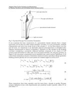
Fig. 4. Flexspar Fin Anatomy

