Advances in Flight Control Systems Part 15 doc
Bạn đang xem bản rút gọn của tài liệu. Xem và tải ngay bản đầy đủ của tài liệu tại đây (389.18 KB, 20 trang )
Comparison of Flight Control System Design Methods in Landing
267
[
]
pd P D
KKe
ν
=
(32)
The compensator gain matrices
,
PD
KK R
∈
are chosen so that the tracking error dynamics
given by
[
]
ad
eAeBv
=
+−Δ
(33)
00
,
PD
I
AB
KK I
⎡
⎤⎡⎤
==
⎢
⎥⎢⎥
−−
⎣
⎦⎣⎦
(34)
are stable, i.e., the eigenvalues of
A are prescribed. It is evident from Eq. (33) that the role of
the adaptive component
ad
v is to cancel
Δ
.The adaptive signal is chosen to be the output of
a single hidden layer [26].
()
TT
ad
WVx
νσ
= (35)
where
V and W are the input and output weighting matrices, respectively, and σ is a
sigmoid activation function. Although ideal weighting matrices are unknown and usually
cannot be computed, they can be adapted in real time using the following NN weights
training rules [27]:
(
)
TT
W
WVxePBeW
σσ κ
⎡⎤
′
=
−− + Γ
⎣⎦
(36)
TT
V
V xe PBW e V
κ
⎡
⎤
=−Γ +
⎣
⎦
(37)
where
,
WV
ΓΓand ,
WV
Γ
Γ are the positive definite learning rate matrices, and κ is the e-
modification parameter. Here,
P is a positive definite solution of the Lyapunov equation
0
T
AP PA Q++=for any positive definite Q .
B. Fuzzy Logic-Based Control Design
The existing applications of fuzzy control range from micro-controller based systems in
home applications to advanced flight control systems. The main advantages of using fuzzy
are as follows:
1.
It is implemented based on human operator’s expertise which does not lend itself to
being easily expressed in conventional proportional integral-derivative parameters of
differential equations, but rather in action rules.
2.
For an ill-conditioned or complex plant model, fuzzy control offers ways to implement
simple but robust solutions that cover a wide range of system parameters and, to some
extent, can cope with major disturbances.
The aircraft landing procedures admit a linguistic describing. This is practiced, for example,
in case of guiding for landing in non-visibility conditions or in piloting learning. This
approach permits to build a model for landing control based on the reasoning rules using
the fuzzy logic. The process requires the control of the following parameters: the current
altitude to runway surface (
H), the aircraft's vertical speed and aircraft flight speed. The goal
of the control is formulated as follow: the aircraft should touch the runway (
H becomes 0) at
the conventional point of landing with admitted vertical touch speed and the recommended
Advances in Flight Control Systems
268
landing speed. The input of FLC normally includes the error between the state variable and
its set point,
()
d
ex x=− and the first derivative of the error, e
. A typical form of the
linguistic rules is represented as
Rule i Th: If e is
i
A and e
is
i
B then
*
u
is
i
C
Where
ii
A,B,and
i
C are the fuzzy sets for the error, the error rate, and the controller
output at rule i, respectively, and
*
u
is the controller output.
The resulting rule base of FLC is shown in Table 2. The abbreviations representing the fuzzy
sets
N, Z, P, S, and B in linguistic form stand for negative, zero, positive, small, and big,
respectively, for example negative big (
NB). Five fuzzy sets in triangular membership
functions are used for FLC input variables, e and e
, and FLC output,
*
u . For the fuzzy
inference or rule firing, Mamdani-type min-max composition is employed. In the
defuzzification stage, by adopting the method of center of gravity, the deterministic control
u is obtained. The membership functions have been designed for input and output diagram
using the trapezoidal shapes, as shown in Figures 1, 2. The fuzzy control system design with
a simple longitudinal aircraft model given by Eqs. (1-6).
Advantages over Conventional Designs
1. Fuzzy guidance and control provides a new design paradigm such that a control
mechanism based on expertise can be designed for complex, ill-defined flight dynamics
without knowledge of quantitative data regarding the input-output relations, which are
required by conventional approaches. A fuzzy logic control scheme can produce a higher
degree of automation and offers ways to implement simple but robust solutions that cover
a wide range of aerodynamic parameters and can cope with major external disturbances.
2.
Artificial Neural networks constitute a promising new generation of information
processing systems that demonstrate the ability to learn, recall, and generalize from
training patterns or data. This specific feature offers the advantage of performance
improvement for ill-defined flight dynamics through learning by means of parallel and
distributed processing. Rapid adaptation to environment change makes them
appropriate for guidance and control systems because they can cope with aerodynamic
changes during flight.
5. Simulation results and discussion
Simulations are performed at sea level, airspeed of 210 ft/s, corresponding to the flare
maneuver configuration of the
Boeing 727. The simulation results are presented in Figs 3 to
8. Figure 3, which depicts the flight speed variation, demonstrates that the engines can
regulate slight speed until that is compromised for attitude rate control. Time histories of the
controls are shown in Fig. 4. The time response of pitch angle is shown in fig.5. A
comparison between the commanded altitude profile and the actual aircraft response is
presented in Fig. 6, it shows that the difference between the actual and desired trajectory
(the fuzzy logic, neural net-based adaptive and optimal controls) is kept less than about 6ft.
This figure, so shows that the sink rate (the rate of descent) is reduced to less than 1.0 ft/sec,
which is small enough to achieve a smooth landing. The fuzzy logic, neural net-based
adaptive and optimal control approaches do the flare maneuver well, while the Pole
Placement Method has substantially large error. Neural network adaptation signal
v
ad
for
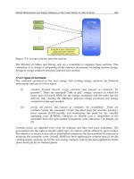
compensate inversion error is presented in Fig. 7. Summarizing the results presented so far,
the nonlinear controller performance for this maneuver has been found very good.
Comparison of Flight Control System Design Methods in Landing
269
-5 0 5 10 15
0
0.2
0.4
0.6
0.8
1
Height
Degree of membership
NB NS Z PS PB
Fig. 1. Altitude Membership Functions
-20 -15 -10 -5 0 5
0
0.2
0.4
0.6
0.8
1
Force
Degree of membership
NB NS Z PS PB
Fig. 2. Force Membership Functions
Advances in Flight Control Systems
270
0 1 2 3 4 5 6 7 8
204
205
206
207
208
209
210
211
Speed (ft/s)
Time
NN
optimal
fuzzy
poleplace
Fig. 3. Time response of the airspeed
0 1 2 3 4 5 6 7 8
-12
-10
-8
-6
-4
-2
0
de (deg)
Time
NN
optimal
fuzzy
poleplace
Fig. 4. Time response of the elevator
Comparison of Flight Control System Design Methods in Landing
271
0 1 2 3 4 5 6 7 8
8
8.5
9
9.5
10
10.5
11
11.5
12
pitch angle (deg)
Time
NN
optimal
fuzzy
poleplace
Fig. 5. Time response of the pitch angle
0 1 2 3 4 5 6 7 8
-10
-5
0
5
10
15
20
25
30
35
Altitude (m)
Time
NN
NN
optimal
fuzzy
fuzzy
poleplace
poleplace
command
Fig. 6. Desired and actual flare trajectories
Advances in Flight Control Systems
272
0 1 2 3 4 5 6 7 8
-0.08
-0.06
-0.04
-0.02
0
0.02
0.04
ouput neural network
Time
neural network(NN)
Fig. 7. NN adaptation signal
ad
ν
0 1 2 3 4 5 6 7 8
-0.07
-0.06
-0.05
-0.04
-0.03
-0.02
-0.01
0
0.01
Lambda q
Time
optimal
Fig. 8. Time response of the
q
λ
Comparison of Flight Control System Design Methods in Landing
273
6. Conclusions
It has been the general focus of this paper to summarize the basic knowledge about
intelligent control structures for the development of control systems. For completeness,
conventional, adaptive neural net-based, fuzzy logic-based, control techniques have been
briefly summarized. Our particular goal was to demonstrate the potential intelligent control
systems for high precision maneuvers required by aircraft landing. The proposed model
reveals the functional aspect for realistic simulation data. The method does not require the
existing controller to be designed based on a linear model.
*
α 12de
g
=
max
α 17.2
=
6
y
I310=×
2
g
32.2ft=
0
B 0.1552=
0
C 0.7125=
42
S 0.156 10 ft=×
1
1
B 0.12369rad
−
=
W 150000Ib
=
2
2
B 2.4203rad
−
=
1
1
C 6.0877rad
−
=
2
2
C 9.0277rad
−
=−
Table 1. model parameter data B-727
Fuzzy set, e
PB PS Z NS NB
Fuzzy set, e
NS PS PS PB PB NB
NB NS PS PS PB NS
NB NS Z PS PB Z
NB NS NS PS PB PS
NB NB NS NS PS PB
Table 2. Rule base for FLC
7. References
[1] Chicago, IL, U.S.A. Locke, A. S., Guidance, D. Van Nostrand Co., Princeton, NJ, U.S.A (1955).
[2] Bryson, A. E., Jr. and Y. C. Ho,
Applied Optimal Control., Blaisdell, Waltham, MA, U.S.A
(1969).
[3] Lin, C. F.,
Modern Navigation, Guidance, and Control Processing, Prentice-Hall, Englewood
Cliffs, NJ, U.S.A (1991).
[4] Zarchan, P.,
Tactical and Strategic Missile Guidance, 2
nd
Ed., AIAA, Inc., Washington, D.C.,
U.S.A (1994).
[5] Bezdek, J., "Fuzzy Models: What are they and Why,"
IEEE Trans. Fuzzy Syst., Vol.1 No.1,
pp, 1-6 (1993).
[6] Miller, W. T., R. S. Sutton, and P. J. Werbos.,
Neural Networks for Control., MIT Press,
Cambridge, MA, U.S.A. Mishra (1991).
[7] Narendra, K. S. and K. Parthasarthy.,
Identification and control of dynamical systems using
neural networks
. IEEE Trans. Neural Networks, 1(1), 4-27 (1990).
Advances in Flight Control Systems
274
[8] Mamdani, E. H. and S. Assilian., An experiment in linguistic synthesis with a fuzzy logic
controller
. Int. J. Man Machine Studies, 7(1), 1-13 (1975).
[9] Lee, C. C., Fuzzy logic in control systems: fuzzy logic controller part I. IEEE Trans. Syst.
Man and Cyb., 20(2), 404-418 (1990).
[10] Lee, C. C., Fuzzy logic in control systems: fuzzy logic controller part II. IEEE Trans. Syst.
Man and Cyb., 20(2), 419-435 (1990).
[11] Driankov, D., H. Hellendoorn, and M. Reinfrank., "
An Introduction to Fuzzy Control".
Springer, Berlin, Germany. Driankov (1993).
[12] Dash, P. K., S. K. Panda, T. H. Lee and J. X. Xu.,
Fuzzy and neural controllers for dynamic
systems: an overview
. Proc. Int. Conf. Power Electronics, Drives and Energy Systems,
Singapore (1997).
[13] BULIRSCH,R., F. Montone, and H. Pesch, "Abort Landing in the Presence of Windshear
as a minimax optimal Control Problem, Part 1: Necessary Conditions",
J. Opt.
Theory Appl
., Vol. 70,pp. 1-23 (1991).
[14] Price, C. F. and R. S. Warren, "Performance Evaluation o f Homing Guidance Laws for
Tactical Missiles," TASC Tech (1973).
[15] Nesline, F. W., B. H. Wells, and P. Zarchan, "Combined optimal/classical approach to
robust missile autopilot design,"
AIAA J. Guid. Contr., Vol.4,No.3, pp.316-322 (1981).
[16] Nesline, F.W. and M.L. Nesline, “How Autopilot Requirements Constrain the
Aerodynamic Design of Homing Missiles,”
Proc. Amer. Contr. Conf., San Diego, CA,
USA, pp.176-730 (1984).
[17] Stallard, D. V., "An Approach to Autopilot Design for Homing Interceptor Missiles,"
AIAA Paper 91-2612, AIAA, Washington, D.C., U.S.A, pp. 99-113 (1991).
[18] Lin, C.F., J. Cloutier, and J. Evers, “Missile Autopilot Design Using a Generalized
Hamiltonian Formulation,”
Proc. IEEE 1st Conf. Aero. Contr. Syst., Westlake Village,
CA, USA, pp. 715-723 (1993).
[19] Lin, C. F. and S. P. Lee, "Robust missile autopilot design using a generalized singular
optimal control technique,"
J. Guid., Contr., Dyna., Vol. 8, No. 4, pp. 498-507 (1985).
[20] Lin, C. F.
Advanced Control System Design. Prentice- Hall, Englewood Cliffs, NJ, U.S.A (1994).
[21] Stoer J. and R. Burlisch,
Introduction to Numerical Analysis, Springer Verlag, New York, (1980).
[22] Oberle, H.J, "BNDSCO-A Program for the Numerical Solution of Optimal Control
Problems," Internal Report No.515-89/22, Institute for Flight Systems Dynamics,
DLR, Oberpfaffenhofen, Germany (1989).
[23] Rysdyk, R., B. Leonhardt, and A.J. Calise, “Development of an Intelligent Flight
Propulsion Control System: Nonlinear Adaptive Control,” AIAA- 2000-3943,
Proc.
Guid. Navig. Contr. Conf.
, Denver, CO, USA (2000).
[24] Isodori, A.,
Nonlinear Control Systems, Springer Verlag, Berlin (1989).
[25] Calise, A. J., S. Lee, and M. Sharma, "Development of a reconfigurable flight control law
for the X-36 tailless fighter aircraft,"
Proc. AIAA Guid. Navig. Contr. Conf., Denver,
CO, USA., AIAA-2000-3940 (2000).
[26] Hornik, K., M. Stinchcombe, M. and H. White, “Multilayer Feedforward Networks are
Universal Approximators,”
Neural Networks, Vol. 2, pp. 359-366 (1989).
[27] Johnson, E. and A.J. Calise, “Neural Network Adaptive Control of Systems with Input
Saturation,” Proc.
Amer. Contr. Conf., pp. 3527–3532. (2001).
14
Oscillation Susceptibility of an
Unmanned Aircraft whose Automatic
Flight Control System Fails
Balint Maria-Agneta and Balint Stefan
West University of Timisoara
Romania
1. Introduction
Interest in oscillation susceptibility of an aircraft was generated by crashes of high
performance fighter airplanes such as the YF-22A and B-2, due to oscillations that were not
predicted during the aircraft development. Flying qualities and oscillation prediction, based
on linear analysis, cannot predict the presence or the absence of oscillations, because of the
large variety of nonlinear interactions that have been identified as factors contributing to
oscillations. Pilot induced oscillations have been analyzed extensively in many papers by
numerical means.
Interest in oscillation susceptibility analysis of an unmanned aircraft, whose flight control
system fails, was generated by the need to elaborate an alternative automatic flight control
system for the Automatic Landing Flight Experiment (ALFLEX) reentry vehicle for the case
when the existing automatic flight control system of the vehicle fails.
The purpose of this chapter is the analysis of the oscillation susceptibility of an unmaned
aircraft whose automatic flight control system fails. The analysis is focused on the research
of oscillatory movement around the center of mass in a longitudinal flight with constant
forward velocity (mainly in the final approach and landing phase). The analysis is made in a
mathematical model defined by a system of three nonlinear ordinary differential equations,
which govern the aircraft movement around its center of mass, in such a flight. This model
is deduced in the second paragraph, starting with the set of 9 nonlinear ordinary differential
equations governing the movement of the aircraft around its center of mass.In the third
paragraph it is shown that in a longitudinal flight with constant forward velocity, if the
elevator deflection outruns some limits, oscillatory movement appears. This is proved by
means of coincidence degree theory and Mawhin's continuation theorem. As far as we
know, this result was proved and published very recently by the authors of this chapter
(research supported by CNCSIS-–UEFISCSU, project number PNII – IDEI 354 No. 7/2007)
and never been included in a book concerning the topic of flight control.The fourth
paragraph of this chapter presents mainly numerical results. These results concern an Aero
Data Model in Research Environment (ADMIRE) and consists in: the identification of the range
of the elevator deflection for which steady state exists; the computation of the manifold of
steady states; the identification of stable and unstable steady states; the simulation of
successful and unsuccessful maneuvers; simulation of oscillatory movements.
Advances in Flight Control Systems
276
2. The mathematical model
Frequently, we describe the evolution of real phenomena by systems of ordinary differential
equations. These systems express physical laws, geometrical connections, and often they are
obtained by neglecting some influences and quantities, which are assumed insignificant
with respect to the others. If the obtained simplified system correctly describes the real
phenomenon, then it has to be topologically equivalent to the system in which the small
influences and quantities (which have been neglected) are also included. Furthermore, the
simplified system has to be structurally stable. Therefore, when a simplified model of a real
phenomenon is build up, it is desirable to verify the structural stability of the system. This
task is not easy at all. What happens in general is that the results obtained in simplified
model are tested against experimental results and in case of agreement the simplified model
is considered to be authentic. This philosophy is also adapted in the description of the
motion around the center of gravity of a rigid aircraft. According to Etkin & Reid, 1996;
Cook, 1997, the system of differential equations, which describes the motion around the
center of gravity of a rigid aircraft, with respect to an xyz body-axis system, where xz is the
plane of symmetry, is:
cos cos cos sin sin cos sin sin cos
sin
sin cos sin cos cos cos sin cos
sin cos sin sin cos cos sin cos cos
cos cos
V
rq
V
g
X
VmV
g
VY
pr
VVmV
V
pq
V
g
V
αββαβααβ β αβ
θ
ββ β α β α β ϕ θ
α
ββ α βα α β β α β
ϕ
⋅ ⋅ −⋅ ⋅ −⋅ ⋅ =⋅ −⋅ ⋅ −
⋅+
⋅
⋅+⋅=⋅⋅−⋅⋅+⋅⋅+
⋅
⋅⋅−⋅⋅+⋅⋅ =−⋅+⋅⋅+
⋅⋅
D
DD
D
D
D
DD
()
()
()
()
22
sin tan cos tan
cos sin
sin cos
cos
xxz yz xz
yzxxz
zxz xy xz
Z
mV
IpI r I I qrI pqL
Iq I I prI p r M
IrI p I I pqI qrN
pq r
qr
qr
θ
ϕϕθϕθ
θϕϕ
ϕϕ
ψ
θ
⎧
⎪
⎪
⎪
⎪
⎪
⎪
⎪
⎪
⎪
⎪
⎪
⎪
⎪
⎪
+
⎪
⋅
⎪
⎨
⋅− ⋅= − ⋅⋅+ ⋅⋅+
⎪
⎪
⎪
⋅=−⋅⋅−⋅−+
⎪
⎪
⎪
⋅− ⋅ = − ⋅ ⋅ − ⋅ ⋅ +
⎪
⎪
=+⋅ ⋅ +⋅ ⋅
⎪
⎪
⎪
=⋅ −⋅
⎪
⋅+⋅
⎪
=
⎪
⎪
⎪
⎩
DD
D
DD
D
D
D
(1)
The state parameters of this system are: forward velocity V, angle of attack α, sideslip angle
β, roll rate p, pitch rate q, yaw rate r, Euler roll angle φ, Euler pitch angle θ and Euler yaw
angle ψ. The constants I
x
, I
y
and I
z
-moments of inertia about the x, y and z-axis, respectively;
Oscillation Susceptibility of an Unmanned Aircraft whose Automatic Flight Control System Fails
277
I
xz
- product of inertia, g -gravitational acceleration; and m - mass of the vehicle. The aero
dynamical forces X, Y, Z and moments L, M, N are functions of the state parameters and the
control parameters: δ
a
-
aileron deflection; δ
e
- elevator deflection; and δ
r
- rudder deflection
(the body flap, speed break, δ
c
, δ
ca
are available as additional controls but, for simplicity,
they are set to 0 in the analysis to follow). When the automatic flight control system is in
function, then the control parameters are functions of the state parameters, describing how
the flight control system works. When the automatic flight control system fails, then the
control parameters are constant. This last situation will be analyzed in this chapter.
A flight with constant forward velocity V is defined as a flight for which V = const (i.e.
0V =
D
).
In a flight with constant forward velocity V the following equalities hold:
cos sin sin cos sin sin cos sin
cos sin cos cos cos sin cos
sin sin cos cos sin cos cos cos cos
g
X
rq
VmV
g
Y
pr
VmV
g
Z
pq
VmV
βα βαα β β α β θ
ββ αβ αβ ϕθ
βα βαα β β α β ϕ θ
⎧
−⋅ ⋅ −⋅ ⋅ =⋅ −⋅ ⋅ − ⋅ +
⎪
⋅
⎪
⎪
⋅=⋅⋅−⋅⋅+⋅⋅+
⎨
⋅
⎪
⎪
−⋅⋅+⋅⋅=−⋅+⋅⋅+⋅⋅+
⎪
⋅
⎩
DD
D
DD
(2)
Replacing V
D
by 0 in the system (1), the equalities(2) are obtained.
If in a flight with constant forward velocity V one has
()
21
2
n
π
β
≡
+⋅
, then the following
equalities hold:
()
()
1
1sin 0
sin cos 0
1coscos0
n
n
g
X
r
VmV
g
Y
VmV
g
Z
p
VmV
θ
ϕθ
ϕθ
+
⎧
−⋅−⋅ + ≡
⎪
⋅
⎪
⎪
⋅⋅+ ≡
⎨
⋅
⎪
⎪
−
⋅+ ⋅ ⋅ + ≡
⎪
⋅
⎩
(3)
Replacing
0
β
=
D
and (2 1)
2
n
π
β
≡
+⋅ in (2), the equalities (3) are obtained.
If in a flight with constant forward velocity V one has
()
21
2
n
π
β
≠
+⋅ , then the following equality
holds:
sin sin cos cos cos sin sin cos cos cos sin
cos cos sin cos 0
Y
g
m
XZ
mm
β
ϕθ α βθ αβϕθ β
αβ αβ
⋅
⋅−⋅⋅+⋅⋅⋅ +⋅+
⎡⎤
⎣⎦
+⋅ ⋅ +⋅ ⋅ ≡
(4)
Equation (4) is the solvability (compatibility) condition, with respect to ,
α
β
DD
, of the system
(2) when
()
21
2
n
π
β
≠+⋅.
Advances in Flight Control Systems
278
If
()
21
2
n
π
β
≠+⋅ and equality (4) holds, then the system (2) can be solved with respect to ,
α
β
DD
,
obtaining in this way the explicit system of differential equations, which describes the motion around
the center of mass of the aircraft in a flight, with constant forward velocityV:
()
()
2
cos tan sin tan cos cos cos
cos
1
sin sin cos sin
cos
11
sin cos sin cos
cos cos
xxz yz xz
yzxxz
g
qp r
V
ZX
mV mV
g
Y
pr
VmV
IpI r I I qrI pqL
Iq I I prI p r
α
αβ αβ ϕθα
β
θα α α
β
βαα ϕθ
ββ
=−⋅ ⋅ −⋅ ⋅ + ⋅ ⋅ ⋅ +
⎡
⎣
⋅
⎡⎤
+⋅ + ⋅ ⋅ − ⋅
⎤
⎦
⎢⎥
⋅⋅
⎣⎦
=⋅−⋅+⋅⋅⋅+⋅
⋅
⋅− ⋅= − ⋅⋅+ ⋅⋅+
⋅=−⋅⋅−⋅−
D
D
DD
D
()
()
2
sin tan cos tan
cos sin
sin cos
cos
zxz xy xz
M
IrI p I I pqI qrN
pq r
qr
qr
ϕϕθϕθ
θϕϕ
ϕϕ
ψ
θ
⎧
⎪
⎪
⎪
⎪
⎪
⎪
⎪
⎪
⎪
⎪
⎪
⎪
⎪
+
⎨
⎪
⎪
⋅− ⋅ = − ⋅ ⋅ − ⋅ ⋅ +
⎪
⎪
⎪
=+⋅ ⋅ +⋅ ⋅
⎪
⎪
=⋅ −⋅
⎪
⎪
⋅+⋅
=
⎪
⎪
⎪
⎪
⎩
DD
D
D
D
(5)
System (5) is obtained solving system (2) with respect to
α
D
,
β
D
and replacing in system (1)
the equations (1)
1
, (1)
2
, (1)
3
with the obtained
α
D
and
β
D
.
A
longitudinal flight is defined as a flight for which the following equalities hold:
0pr
βϕψ
≡
≡≡ ≡ ≡
and
0
ar
δδ
=
=
. (6)
A longitudinal flight is possible if and only if 0YLN
=
== for 0pr
β
ϕψ
=
== = = and
0
ar
δ
δ
==.
This result is obtained from (1) taking into account the definition of a longitudinal flight.
The explicit system of differential equations which describes the motion of the aircraft in a
longitudinal flight is:
()
sin( ) cos sin
cos sin cos
y
XZ
Vg
mm
g
XZ
q
VmVmV
M
q
I
q
αθ α α
α
θα α α
θ
⎧
=⋅ − + ⋅ + ⋅
⎪
⎪
⎪
=+ ⋅ − − ⋅ + ⋅
⎪
⎪
⋅⋅
⎨
⎪
=
⎪
⎪
⎪
=
⎪
⎩
D
D
D
D
(7)
Oscillation Susceptibility of an Unmanned Aircraft whose Automatic Flight Control System Fails
279
This result is obtained from (1) taking into account the definition of a longitudinal flight.
In system (7) X, Z, M depend only on
,,q
α
θ
and
e
δ
. These dependences are obtained
replacing in the general expression of the aerodynamic forces and moments:
0pr
β
ϕψ
==== = and 0
ar
δ
δ
=
= .
The explicit system of differential equations which describes the motion around the center of gravity
of the aircraft in a longitudinal flight with constant forward velocity V is:
()
cos sin cos
y
g
XZ
q
VmVmV
M
q
I
q
α
θα α α
θ
⎧
=+ ⋅ − − ⋅ + ⋅
⎪
⋅⋅
⎪
⎪
=
⎨
⎪
⎪
⎪
=
⎩
D
D
D
(8)
This system is obtained from (7) taking into account 0V
=
D
.
A longitudinal flight with constant forward velocity is possible if the following equalities hold:
000
ar
YLN for pr and
β
ϕψ δ δ
=
== ===== == (9)
()
sin cos sin 0
XZ
g
mm
αθ α α
⋅
−+⋅ +⋅ =
(10)
This result is obtained from system (7), taking into account the fact that
V
D
is equal to zero.
In (8) ,,XZMdepend on ,,,
e
q
α
θδ
and V . Taking into account (10), the system (8) can be
written as:
() ()
1
cos sin tan
cos
y
gg
Z
q
VV mV
M
q
I
q
αθαθαα
α
θ
⎧
=+ ⋅ − − ⋅ − ⋅ + ⋅
⎪
⋅
⎪
⎪
⎪
=
⎨
⎪
⎪
⎪
=
⎪
⎩
D
D
D
(11)
The system (11) describes the motion around the center of gravity of an aircraft in a
longitudinal flight with constant forward velocity V and defines the general nonlinear
model.
In system (11) the functions
(,,; ,)
e
ZZ q V
α
θδ
=
and (,,; ,)
e
M
Mq V
α
θδ
=
are considered
known. When the automated flight control system fails,
e
δ
and V are parameters.
Frequently, in a research environment for the description of the movement around the
center of the gravity of some types of aircrafts in a flight with constant forward velocity V,
the explicit system of differential equations (12) is employed by Balint et al., 2009a,b,c;
2010a,b; Kaslik & Balint, 2007; Goto & Matsumoto, 2000.
The model defined by equations (12) is called Aero Data Model In a Research Environment
(ADMIRE).
Advances in Flight Control Systems
280
System (12) can be obtained from (5) substituting the general aero dynamical forces and moments
(see for example section 4), assuming that α and β are small and making the approximations (13).
Due to the approximations (13), the ADMIRE model defined by (12) is also called the
simplified ADMIRE model.
The simplified system which governs the longitudinal flight with constant forward velocity
Vof the
ADMIRE aircraft is (14).
System (14) is obtained from (12) for
0pr
β
ϕ
=
== =, 0
arcca
δ
δδδ
=
== = and defines the
simplified nonlinear model of the motion around the center of gravity of the aircraft in a
longitudinal flight with constant forward velocity V.
In system (14)
22
,, , , , , , , ,,
ee
q
gVzz mmmcaam
α
α
δα δ
D
are considered constants (see Section 4).
2
1
cos cos ( , ) ( )
sin cos ( , ) ( )
() ()
aer
ae r
ar
pr
ae r
pr
aer
pr a r
g
qp z y y p y r
V
yzy
g
pr z y y py r
V
yz y
piqrl lpl rl l
αβ
δδδ
αβ
δδ δ
βδδ
αβ θϕαβαββββ
βδ δ βδ
βα ϕθ αβ β αβ β
δβδδ
αβ α δ δ
=−⋅+ ⋅ ⋅ + ⋅+ ⋅ + ⋅⋅+ ⋅⋅+
+⋅⋅+⋅+⋅⋅
=⋅−+ ⋅ ⋅ − ⋅⋅+ ⋅− ⋅− ⋅+
+⋅−⋅⋅+⋅
=−⋅⋅+ ⋅ + ⋅+ ⋅+ ⋅ + ⋅
D
D
D
2
2
2
2
3
()
cos cos sin
(, ) (, ) ()
(sin cos)
ac
er
aca r
qp r
ac
er
p
racar
qiprm mqmp yp y y r
g
c
maym
Va
my
ripqn n pn rn n n
pq r
αβ
α
δδ
α
δδ
βδδδ
αβββββ
θϕ θ βδ δ
δβδ
β
αβ αβ δ α δ δ
φϕϕ
=⋅⋅+ ⋅+ ⋅− ⋅⋅+ ⋅⋅+ ⋅ + ⋅⋅+
⎛⎞
+⋅ ⋅ ⋅ − ⋅⋅ + ⋅⋅+ ⋅+
⎜⎟
⎝⎠
+⋅+⋅⋅
=− ⋅ ⋅ + ⋅ + ⋅ + ⋅ + ⋅ + ⋅ + ⋅
=+ ⋅ +⋅
D
D
D
D
D
tan
cos sin
sin cos
cos
qr
qr
θ
θϕϕ
ϕϕ
ψ
θ
⎧
⎪
⎪
⎪
⎪
⎪
⎪
⎪
⎪
⎪
⎪
⎪
⎪
⎪
⎪
⎨
⎪
⎪
⎪
⎪
⎪
⎪
⎪
⎪
⋅
⎪
⎪
=⋅ −⋅
⎪
⎪
⋅+⋅
⎪
=
⎪
⎩
D
D
(12)
()()
() ()
1
2
2
1
22
2
3
22
(5) cos 1; cos tan ; sin tan 0; cos 1; sin 0
(5) cos 1
0; ; 0;
;0;
xzxzy yzzxz
xz
y
xz xz xz xz
xz xyx xzyzxz
xz xz xz xz
in p p r
in
I III IIII
I
i
I
II I II I
IIII IIII
i
II I II I
βαββαβαα
β
≈
−⋅⋅≈−⋅−⋅⋅≈ ≈ ≈
⎧
⎪
≈
⎪
⎪
⋅+− −⋅−
⎪
≈≈−≈
⎨
⋅− ⋅−
⎪
⎪
+−⋅ ⋅−−
⎪
≈− ≈
⎪
⋅− ⋅−
⎩
(13)
Oscillation Susceptibility of an Unmanned Aircraft whose Automatic Flight Control System Fails
281
2
2
cos
cos sin
e
e
e
q
e
g
qzz
V
g
c
qm mq m a m
Va
q
α
αδ
αδ
αθαδ
α
θθδ
θ
⎧
=+ ⋅ + ⋅+ ⋅
⎪
⎪
⎪
⎛⎞
=
⋅+ ⋅+ ⋅ ⋅ − ⋅ ⋅ + ⋅
⎨
⎜⎟
⎝⎠
⎪
⎪
=
⎪
⎩
D
D
D
D
(14)
3. Theoretical proof of the existence of oscillatory movements
Interest in oscillation susceptibility of an aircraft is generated by crashes of high
performance fighter airplanes such as the YF-22A and B-2, due to oscillations that were not
predicted during the aircraft development (Mehra & Prasanth, 1998).Flying qualities and
oscillation prediction are based on linear analysis and their quasi-linear extensions. These
analyses cannot, in general, predict the presence or the absence of oscillations, because of the
large variety of nonlinear interactions that have been identified as factors contributing to
oscillations. The effects of some of these factors have been reported by Mehra et al., 1977;
Shamma & Athans, 1991; Kish et al., 1997; Klyde et al., 1997. The oscillation susceptibility
analysis in a nonlinear model involves the computation of nonlinear phenomena including
bifurcations, which lead sometimes to large changes in the stability of the aircraft.
Interest in oscillation susceptibility analysis of an unmanned aircraft, whose flight control
system fails, was generated by the elaboration of an alternative automatic flight control for
the case when the existing automatic flight control system of the aircraft fails Goto &
Matsumoto, 2000. Numerical results concerning this problem for the ALFLEX unmanned
reentry vehicle, considered by Goto & Matsumoto, 2000, for the final approach and landing
phase are reported by Kaslik et al., 2002; 2004 a; 2004 b; 2005 a; 2005 b; 2005 c; Caruntu et al.,
2005.
A theoretical proof of the existence of oscillatory solutions of the ALFLEX unmanned
reentry vehicle in a longitudinal flight with constant forward velocity and decoupled flight
control system is reported Kaslik & Balint, 2010. Numerical results related to oscillation
susceptibility analysis along the path of the longitudinal flight equilibriums of a simplified
ADMIRE-model, when the automated flight control system fails are reported by Balint et al.,
2009 a; 2009 b; 2009 c; 2010 a.
In this section we give a theoretical proof of the existence of oscillatory solutions in
longitudinal flight in the simplified ADMIRE model of an unmanned aircraft, when the
flight control system fails. This result was established by Balint et al., 2010b.
The simplified system of differential equations which governs the motion around the center
of mass in a longitudinal flight with constant forward velocity of a rigid aircraft, when the
automatic flight control system fails, is given by (see Balint et al., 2010b):
2
2
cos
cos sin
e
e
e
q
e
g
zq z
V
g
c
qm mq m a m
Va
q
αδ
αα δ
αα θ δ
α
θθδ
θ
⎧
=⋅++⋅ + ⋅
⎪
⎪
⎪
⎛⎞
=
⋅+ ⋅+ ⋅ ⋅ − ⋅ ⋅ + ⋅
⎨
⎜⎟
⎝⎠
⎪
⎪
=
⎪
⎩
D
D
D
(15)
Advances in Flight Control Systems
282
In this system, the state parameters are: angle of attack
α
, pitch rate q and Euler pitch
angle
θ
. The control parameter is the elevator angle
e
δ
. V is the forward velocity of the
aircraft, considered constant and g is the gravitational acceleration.
The aero dynamical data appearing in (15) are given in section 4.
The following proposition (Balint et al., 2010b) addresses the existence of equilibrium states
for the system (15).
Proposition 1.
(
)
,
T
q
α
θ
is an equilibrium state of the system (15) corresponding to
e
δ
if and only
if
α
is a solution of the equation:
22
0
ee
AB C D
αδαδ
⋅
+⋅ ⋅+⋅ + = (16)
q
is equal to zero and
θ
is a solution of the equation:
cos
e
e
V
zz
g
αδ
θ
αδ
⎡
⎤
=− ⋅ + ⋅
⎣
⎦
(17)
where A, B, C, D are given by:
()
()()
()
2
2
22
2
2
2
2
2
2
2
2
2
2
22
2
2
2
2
2
2
2
2
22
22
ee e
ee e
c
Ammz az
a
c
Bmmzmmz azz
a
c
Cm mz az
a
g
c
Da
Va
ααα α
α
αα δ αδ αδ
δαδ δ
=−⋅+⋅⋅
=
⋅−⋅⋅ −⋅+⋅⋅⋅⋅
=−⋅+⋅⋅
=− ⋅ ⋅
(18)
Proof. By computation.
Proposition 2. Equation (16) has real solutions if and only if
e
δ
satisfies:
2
4
4
e
AD
BAC
δ
⋅⋅
≤
−
⋅⋅
(19)
Proof. By computation.
Proposition 3. If 0z
α
<
and
α
is a real solution of Eq.(16), then Eq.(17) has a solution if and only
if for
α
the following inequality holds:
11
ee
ee
gg
zz
zV zV
δδ
αα
δ
αδ
⎡
⎤⎡⎤
⋅
−⋅ ≤≤−⋅ +⋅
⎢
⎥⎢⎥
⎣
⎦⎣⎦
(20)
Proof. By computation.
Remark. For 0
e
δ
= the solutions of Eq.(16) are:
()
2
2
2
2
2
22
2
2
22
2
2
2
g
c
a
Va
c
az mmz
a
αααα
α
⋅⋅
=±
⋅⋅ + −⋅
(21)
Oscillation Susceptibility of an Unmanned Aircraft whose Automatic Flight Control System Fails
283
and both verify (20) for 0z
α
<
.
In the following assume that 0z
α
<
and consider
e
δ
,
e
δ
defined as follows:
{
}
inf 0, .(16) (20)
eee
a real solution of eq for which holds
δδδ
=<∃
{
}
sup 0, .(16) (20)
eee
a real solution of eq for which holds
δδδ
=>∃
Let
I be the closed interval [,]
ee
I
δ
δ
= .
Proposition 4.
a. If
e
I
δ
∈ , then for the system (15) there exists a countable infinity of equilibriums corresponding to
e
δ
, namely for any n Z
∈
()
()
22 2
1,2
1,2
1
4;0;
22
2arccos
e
eee
ne
B
BACDq
AA
V
nzz
g
αδ
αδ δ δ
θπ α δ
±
⎛
=
−⋅±⋅⋅−⋅⋅⋅+ =
⎜
⋅⋅
⎝
⎞
⎡⎤
=⋅⋅± ⋅− ⋅ − ⋅
⎟
⎢⎥
⎟
⎣⎦
⎠
b. If
{
}
,
eee
I
δ
δδ
∈∂ = , then the equilibriums corresponding to
e
δ
are saddle-node bifurcation points.
c. If
e
I
δ
∈
, then for the system (15) there are no equilibriums corresponding to
e
δ
.
Proof. By computation.
Proposition 4 translates into the following necessary and sufficient condition for the
existence of equilibrium states for (15):
,
eee
I
δ
δδ
⎡
⎤
∈=
⎣
⎦
. At
,
ee
δ
δδ
= saddle-node
bifurcation occurs.
It can be easily verified that the following proposition is valid.
Proposition 5.
a. If
()
(), (), ()
T
tqt t
αθ
is a solution of the system (15), then ()t
θ
is a solution of the third order
differential equation:
()
()
2
2
2
2
sin cos
cos sin
ee
e
g
c
zm zmm m a
Va
gg
c
mzm z a mz zm
VVa
αααα
αα α αδ αδ
α
θθ θθθ
θ
θδ
⎡⎤
⎛⎞
−+⋅+⋅−+⋅ ⋅ +⋅⋅ ⋅=
⎢⎥
⎜⎟
⎝⎠
⎣⎦
⎛⎞
=⋅ −⋅ ⋅ +⋅⋅⋅⋅ + ⋅ −⋅ ⋅
⎜⎟
⎝⎠
D
(22)
b. If
()t
θ
is a solution of (22), then
2
2
1
() cos sin
() ()
() ()
e
q
e
g
c
tmm am
mVa
qt t
tt
αδ
α
α
θθ θ θ δ
θ
θθ
⎡
⎤
⎛⎞
=
⋅− ⋅−⋅ ⋅ −⋅⋅ − ⋅
⎢
⎥
⎜⎟
⎝⎠
⎣
⎦
=
=
is a solution of the system (15).
Proof. By computation.
Advances in Flight Control Systems
284
A solution ()t
θ
of Eq.(22) is called monotonic oscillatory solution if the derivative ()t
θ
is a
strictly positive or a strictly negative periodic function.
Proposition 6. a. If there exists an increasing oscillatory solution ()t
θ
of Eq.(22)and 0T > is the
period of ()t
θ
, then there exists *nN
∈
such that ()()2tT t n
θ
θπ
+
=+ and there exists a 2n
π
-
periodic solution
()xs of the equation:
()
()
2 2
2
2
3
2
2
"2(') ' sin cos
cos sin
ee
xx
x
e
g
c
xxzmxezmm m s a se
Va
gg
c
mzm s z a smz zm e
VVa
αααα
αα α αδ αδ
α
δ
⎡⎤
⎛⎞
=++⋅⋅+⋅−+⋅⋅+⋅⋅ ⋅−
⎢⎥
⎜⎟
⎝⎠
⎣⎦
⎡⎤
⎛⎞
− ⋅ −⋅ ⋅ +⋅⋅⋅⋅ + ⋅ −⋅ ⋅ ⋅
⎜⎟
⎢⎥
⎝⎠
⎣⎦
D
(23)
satisfying
2
()
0
n
xs
edsT
π
⋅
=
∫
(24)
b.
If for *nN∈ there exists a 2n
π
- periodic solution ()xs of Eq.(23), then there exists an increasing
oscillatory solution
()t
θ
of Eq.(22) satisfying
()()2tT t n
θ
θπ
+= +
, where
T
is given by (24).
Proof. See Balint et al., 2010b.
In order to prove that Eq.(22) has an increasing oscillatory solution, it is sufficient to prove
that there exists a 2
n
π
- periodic solution of the Eq.(23).
Denoting
1
xx= and
2
2
() '
xx
q
xzmexe
α
−−
=− + ⋅ − ⋅ , eq.(23) is replaced by the system:
()
()
11
1
2
12
2
2 2
2
2
'( )
'cossin
sin cos
ee
xx
q
x
e
q
xzmexe
gg
c
xzmmz mzmszase
VVa
g
c
zm m m s a s
Va
α
αδ αδ α αα α
αα α
δ
=− + ⋅ − ⋅
⎡⎤
=−⋅ + ⋅ ⋅ + ⋅ − ⋅ ⋅ + ⋅ ⋅ ⋅ ⋅ ⋅ −
⎢⎥
⎣⎦
⎡⎤
⎛⎞
−⋅−+⋅ ⋅ +⋅⋅
⎢⎥
⎜⎟
⎝⎠
⎣⎦
(25)
Proposition 7. a. If there exists a decreasing oscillatory solution ()t
θ
of (22) and 0T > is the period
of
()t
θ
, then there exists *nN
∈
such that
()()2tT t n
θ
θπ
+= −
and there exists a 2n
π
- periodic
solution
()xs of the equation:
()
()
2 2
2
2
3
2
2
"2(') ' sin cos
cos sin ( )
e
xx
x
ee
g
c
xxzmxezmm m s a se
Va
gg
c
mzm s z a sm zm e
VVa
αααα
ααα α α αδ
δδ
⎡⎤
⎛⎞
=−+⋅⋅+⋅−+⋅⋅+⋅⋅ ⋅+
⎢⎥
⎜⎟
⎝⎠
⎣⎦
⎡⎤
+ ⋅ −⋅ ⋅ +⋅⋅⋅⋅ + ⋅−⋅ ⋅ ⋅
⎢⎥
⎣⎦
(26)
satisfying
2
()
0
n
xs
Teds
π
=
⋅
∫
(27)
Oscillation Susceptibility of an Unmanned Aircraft whose Automatic Flight Control System Fails
285
b. If for *nN∈ , there exists a 2n
π
- periodic solution ()xs of(26), then there exists a decreasing
oscillatory solution
()t
θ
of (22), satisfying ()()2tT t n
θ
θπ
+
=− with T given by (27).
Proof. See Balint et al., 2010b.
It follows that in order to prove that Eq.(22) has a decreasing oscillatory solution, it is
sufficient to prove that there exists a 2
n
π
- periodic solution of the Eq.(26).
Denoting by
1
xx=
and
2
2
() '
xx
q
xzmexe
α
−−
=+⋅+⋅ Eq.(26) is replaced by the system:
()
()
11
1
2
12
2
2 2
2
2
'( )
'cossin
sin cos
ee
xx
q
x
e
q
xzmexe
gg
c
xzmmz mzmszase
VVa
g
c
zm m m s a s
Va
α
αδ αδ α αα α
αα α
δ
=+⋅+⋅
⎡⎤
=−⋅ + ⋅ ⋅ + ⋅ − ⋅ ⋅ + ⋅ ⋅ ⋅ ⋅ ⋅
⎢⎥
⎣⎦
⎡⎤
⎛⎞
+⋅−+⋅ ⋅ +⋅⋅
⎢⎥
⎜⎟
⎝⎠
⎣⎦
(28)
Hence, in order to show the existence of a decreasing oscillatory solution of Eq.(22) it is
sufficient to show the existence of a 2
n
π
- periodic solution of (28).
For a continuous 2n
π
periodic function we define:
0, 2
max ( )
M
sn
ff
s
π
∈
⎡⎤
⎣⎦
=
0, 2
min ( )
L
sn
ff
s
π
∈
⎡⎤
⎣⎦
=
Proposition 8. If
f
is a smooth 2n
π
periodic function, then
2
0
1
()
2
n
ML
ff f
sds
π
≤
+⋅ ⋅
∫
.
Proof. See Balint et al., 2010b.
Let
,XY
be two infinite dimensional Banach spaces. A linear operator
:LDomL X Y⊂→
is
called a Fredholm operator if
Ker L
has finite dimension and
ImL
is closed and has finite
codimension. The index of a Fredholm operator
L
is the integer
() dim dimImiL KerL co L=−
.
In the following, consider
:LDomL X Y⊂→
a Fredholm operator of index zero, which is
not injective. Let :
PX X→ and :QY Y→ be continuous projectors, such that
Im , Im ,KerQ L P KerL X KerL KerP===⊕
and Im ImYLQ
=
⊕ . The operator
:Im
PDomLKerP
LL DomLKerP L
∩
=∩→ is an isomorphism. Consider the operator
:
PQ
KYX→ defined by
1
()
PQ P
KKIQ
−
=−. Let
X
Ω
⊂
be an open bounded set and
:NYΩ→ be a continuous nonlinear operator. We say that N is
L
compact if
PQ
KNis
compact, QN is continuous and
()QN
Ω
is a bounded set in
Y
. Since ImQ is isomorphic to
KerL , there exists an isomorphism : ImIQKerL→ .
Mawhin, 1972; Gaines & Mawhin, 1977 established the Mawhin’s continuation theorem : Let
XΩ⊂ be an open bounded set, let L be a Fredholm operator of index zero and let N be L − compact
on
Ω
. Assume:
a. Lx Nx
λ
≠ for any
(
)
0, 1
λ
∈ and x DomL
∈
∂Ω ∩ .
b. QNx ≠ 0 for any x KerL
∈
∩∂Ω.
Advances in Flight Control Systems
286
c. Brouwer degree de
g
(, ,0)0
B
IQN KerL
Ω
∩≠.
Then Lx Nx= has at least one solution in
DomL
∩
Ω .
Consider the Eq.(22) and denote by:
()
()
2
2
2
2
()
sin cos
sin
ee
q
q
e
zm
g
c
zm m m a
Va
g
c
mz zm z a
Va
g
mzm
V
α
αα α
αδ α δ α
ααα
τ
δ
θθ
γ
δθ
ε
=− +
⎛⎞
=⋅− +⋅ ⋅ +⋅⋅
⎜⎟
⎝⎠
=⋅−⋅⋅+⋅⋅⋅⋅
=− ⋅ − ⋅
(29)
With these notations Eq.(22) can be written as:
cos
θ
τθ δθ γ ε θ
+⋅+⋅=−⋅
(30)
As concerns the quantities
,,
τ
δγ
, we make the following assumptions:
0, 0
τ
δ
>> and
2
4
τ
δ
>
(31)
Remark that the above inequalities can be assured as follows:
(
)
()
()
2
2
2
2
2
2
2
2
222
2
2
2
00
0
4
()4( ) 4
q
q
zm
g
c
zm m m a
V
a
g
c
zm zmm m a
V
a
α
αα α
αααα
τ
δ
τ
δ
+< ⇔>
⋅− >⋅ + ⋅ ⇒>
+>⋅⋅−+⋅ +⋅ ⇒>
(32)
Remark also that since
0z
α
<
for
γ
the following inequality holds:
() ()
22
22
ee ee
ee
gg
cc
mz zm z a mz zm z a
Va Va
αδ α δ α αδ α δ α
δγ δ
⋅−⋅ ⋅−⋅⋅⋅≥≥ ⋅−⋅ ⋅+⋅⋅⋅ (33)
In terms of
,,,
τ
δγε
the systems (25) and (28) can be written in the forms:
11
1
2
12
2
'
'()cos ()
xx
x
xexe
xs ses
τ
γ
εδ
⎧
=⋅ − ⋅
⎪
⎨
=−⋅ ⋅−
⎡⎤
⎪
⎣⎦
⎩
(34)
and
11
1
2
12
2
'
'()cos ()
xx
x
xexe
xs ses
τ
γ
εδ
⎧
=− ⋅ + ⋅
⎪
⎨
=−⋅ ⋅+
⎡⎤
⎪
⎣⎦
⎩
(35)
respectively.