Advances in Vehicular Networking Technologies Part 2 pot
Bạn đang xem bản rút gọn của tài liệu. Xem và tải ngay bản đầy đủ của tài liệu tại đây (3.62 MB, 30 trang )
Advances in Vehicular Networking Technologies
22
message propagation will have a maximum bound equal to v
V2I
, while for reverse message
propagation
range the maximum bound is —v
V2I
.
The definitions for
forward and reverse message propagation rates are given below,
respectively.
Definition (Forward Message Propagation rate): the forward message propagation rate, when a
vehicle is communicating via V2V, is in the range [c,
()
V2V
v
+
]. In contrast, when a vehicle
communicates via V2I, the forward message propagation rate is in the range [c, v
V2I
].
Definition (Reverse Message Propagation rate): the reverse message propagation rate, when a
vehicle communicates via V2V, is in the range [—c,
()
V2V
v
−
], while for vehicles communicating via
V2I, the range of reverse message propagation rate is [—c, —v
V2I
].
5.2 V2X algorithm
This section illustrates how V2X takes a protocol switching decision.
The algorithm for handing over from V2V to V2I, and vice versa, is described by its pseudo-
code in Figure 11. It is mainly based on (
i) the Infrastructure Connectivity (IC) parameter,
which gives information if a vehicle is able to connect to an RSU, and on (
ii) the optimal path
detection technique
. The algorithm accepts one input (i.e., the vehicle’s IC), and returns the
actual message propagation rate (
i.e., {v
V2V
, v
V2I
}).
Input : IC
Output :
v
V2V
, if a vehicle communicates via V2V
v
V2I
, if a vehicle communicates via V2I
⎧
⎨
⎪
⎩
⎪
while IC = 0 do
A vehicle is connected via V2V, ← v
V2V
end
else
if IC = 1 then
Optimal path detection, ← v
V2I
or v
V2V
end
end
if A vehicle communicates with an RSU via V2I then
the RSU tracks the destination's position,
if Destination vehicle is inside the actual RSUs coverage then
Direct link from RSU to destination vehicle
else
The actual RSU will forward the message to next RSU
end
end
end
Fig. 11. Algorithm for protocol switching decisions in V2X
Seamless Connectivity Techniques in Vehicular Ad-hoc Networks
23
Let us consider the following VANET scenario. A source vehicle is communicating with
other vehicles (
relay) via V2V in a sparsely connected neighbourhood, where the
transmission range distance between two consecutive vehicles is under a connectivity
bound,
i.e. x ≤ 125 m.
The source vehicle is driving inside any wireless cell, and is receiving "hello" broadcast
messages from other vehicles nearby. Local connectivity information will notify the vehicle
the availability of vehicles to communicate with via V2V; no RSU presence will be notify to
the vehicle. In this case (
i.e., V2V availability, and no V2I) the IC parameter for vehicle A will
be set to 0. Otherwise, when a vehicle
enters a wireless network, the presence of an available
RSU to access will be directly sent to the vehicle by means of its associated
IC parameter set
to 1.
Finally, a destination vehicle is driving far away from
A, and other vehicles (relay) are
available to communicate each other.
In such scenario, the algorithm works according to two main tasks, such as (
i) checking IC
parameter, and (
ii) tracking the destination vehicle(s). Every time a vehicle forwards a
message it checks its
IC value. When IC = 1, the vehicle calculates the optimal path according
to (21) in order to send the message directly to the selected RSU via V2I. Otherwise, the
vehicle forwards the message to neighbouring vehicles via V2V.
By supposing the RSU knows the destination vehicle’s position (
i.e. by A-GPS), if the
destination vehicle is traveling within the RSU’s wireless coverage, the RSU will send the
message directly to the destination vehicle. Otherwise, the RSU will be simply forwarding
the message to the RSU that is actually managing the vehicle’s connectivity. Finally, the
message will be received by the destination vehicle.
Some simulation results are now shown in order to verify the effectiveness of V2X
approach as compared with traditional opportunistic networking scheme in VANET. As a
measure of performance, we calculate the
average message displacement (i.e. X [m]) in
VANETs via V2X. The
message displacement is a linear function, depending on time, and
varying for different traffic scenarios, message propagation speeds, and network
conditions. It follows that in each of the six states listed in Section 5.1, the message
displacement
X(t) will be as follows:
1.
() ,Xt c t=⋅ for messages traveling along on a vehicle in the N direction at speed
c [m/s];
2.
()
V2V
() ,Xt v t
+
=⋅
for messages propagating multi-hop within a cluster in the N direction at
speed
()
V2V
v
+
[m/s];
3.
() ,Xt c t=− ⋅ for messages traveling along a vehicle in the S direction at speed —
c [m/s];
4.
()
V2V
() ,Xt v t
−
=⋅ for messages propagating multi-hop within a cluster in the S direction at
speed
()
V2V
v
−
[m/s];
5.
V2I
() ,Xt v t=⋅ for messages transmitted via radio by an RSU in the N direction at speed
v
V2I
[m/s];
6.
V2I
() ,Xt v t=− ⋅ for messages transmitted via radio by an RSU in the S direction at speed
—
v
V2I
[m/s].
States 1, 2, and 5 refer on a
forward message propagation, while stated 3, 4, and 6 on a reverse
message propagation
, respectively.
Advances in Vehicular Networking Technologies
24
We simulated a typical vehicular network scenario by the following events:
i. at t = 0 s a source vehicle is traveling in the N direction and sends a message along on
the same direction, (
state 1);
ii.
at t = 2 s the message is propagated multi-hop within a cluster in the N direction, (state
2);
iii.
at t = 6 s a relay vehicle enters an RSU’s radio coverage, and the message is transmitted
via V2I to the RSU. Finally, it will be received by other vehicles at
t = 10 s, (state 5).
We compared this scenario with traditional opportunistic networking technique in
VANETs, where the following events occur:
i. at t = 0 s a source vehicle traveling in the N direction sends a message along on the
same direction, (
state 1);
ii. at t = 4 s the message is forwarded to a vehicle in the S direction, (state 3);
iii
. at t = 6 s the message propagates via multi-hop within a cluster in the N direction, (state
2). The transmission stops at
t = 10 s.
For comparative purposes, main simulation parameters has been set according to (Wu et al.,
2004), including
c = 20 m/s, d = 500 m, typical message size L = 300 bit, data rate
transmission
B = 10 Mbit/s (e.g., for WiMax connectivity), and x
r
= 400 m. The transmission
rates in DSRC have been assumed equal to 6 Mbit/s (Held, 2007). We assumed a cluster size
equal to
h = 5, and different distances between couples of vehicles (i.e., 100, 75, 50, 40, and
30 m). For each hop the transmission range has been hold (
i.e. < 125 m).
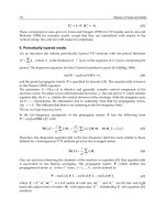
Figure 12 (
left) depicts the maximum and minimum message propagation bounds for V2X in
forward message propagation mode. Notice a strong increase in the message propagation with
respect to other forms of opportunistic networking: after
t = 10 s, the message has been
propagating for approximately 30 km in V2X (Figure 12 (
left)), while only 1.5 km in
traditional V2V (Figure 12 (
right)). The high performance gap is mainly due to the protocol
switching decision of V2X, which exploits high data rates from wireless network
infrastructure. In contrast, opportunistic networking with V2V is limited to use only DSRC
protocol.
Fig. 12. Forward message propagation for (left) V2X protocol, (right) traditional
opportunistic networking
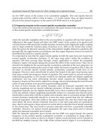
Analogously, we simulated how a message is forwarded in reverse message propagation mode,
where
vehicles are traveling in an opposite direction (Figure 13). In this case, the message
Seamless Connectivity Techniques in Vehicular Ad-hoc Networks
25
propagation rates are in the range [—c; —v
V2I
] and [—c;
()
V2V
v
−
] [m/s], for V2X and traditional
opportunistic networking scheme, respectively. Once again, while V2X assures high values
for message displacement (
i.e., at t = 10 s, a message has been propagated up to around
70 km, as shown in Figure 13 (
left)), traditional V2V can achieve low values (i.e., at t = 10 s,
messages have reached 1.3 km far away from the source vehicle (see Figure 13 (
right)).
Notice the fluctuations of message displacement in
forward and reverse cases with V2X (i.e.
50, and 70 km, respectively). They are mainly due to traffic density, and RSUs’ positions (
i.e.
inter-RSU distance). In general, high performance are obtained with V2X, while low
message propagation distance with traditional V2V.
Fig. 13. Reverse message propagation for (left) V2X protocol, (right) traditional opportunistic
networking
6. Conclusions
In this chapter we have discussed application of VHO in the context of VANETs in order to
optimize application delivery through a mixed V2V/V2I infrastructure. Vertical handover
strategies can be applied to assure VANET connectivity
context-aware, and content-aware.
Various metrics can be adopted to trigger handover decisions including RSS measurements,
QoS parameters, and mobile terminal location information. This last represents the most
common parameter used to drive VHO decisions.
Hence, a geometrical model has been presented where GPS-equipped mobile terminals
exploit their location information to pilot handover and maximize communication
throughput taking into account mobile speed. The proposed technique has been described
via both analytical and simulated results, and validation of its effectiveness has been
supported by a comparison with a traditional vertical handover method for VANETs (Yan
et
al.
, 2008).
Moreover, we have described a hybrid vehicular communication protocol V2X and the
mechanism by which a message is propagated under this technique. V2X differs from
traditional V2V protocol by exploiting both V2V and V2I techniques, through the use of a
fixed network infrastructure along with the mobile ad-hoc network. In this heterogeneous
scenario, we have characterized the upper and lower bounds for message propagation rates.
Validation of V2X has been carried out via simulation results, showing how V2X protocol
Advances in Vehicular Networking Technologies
26
improves network performance, with respect to traditional opportunistic networking
technique applied in VANETs.
7. References
Held, G. (2007). Inter- and intra-vehicle communications, CRC Press.
Chiara, B.D.; Deflorio, F. & Diwan, S. (2009). Assessing the effects of inter-vehicle
communication systems on road safety,
Intelligent Transport Systems, IET, Vol. 3,
No. 2, June 2009, pp. 225–235.
Pollini, G.P. (1996). Trends in handoff design,
IEEE Communication Magazine, Vol. 34, No. 3,
March 1996, pp. 82–90.
Inzerilli, T. & Vegni, A.M. (2008). A reactive vertical handover approach for WiFi-UMTS
dual-mode terminals,
Proceeding of 12th Annual IEEE International Symposium on
Consumer Electronics
, April 2008, Vilamoura (Portugal).
Vegni, A.M.; Tamea, G.; Inzerilli, T. & Cusani, R. (2009). A Combined Vertical Handover
Decision Metric for QoS Enhancement in Next Generation Networks,
Proceedings of
IEEE International Conference on Wireless and Mobile Computing, Networking and
Communications
2009, pp. 233–238, October 2009, Marrakech (Morocco).
Vegni, A.M. & Esposito, F. (2010). A Speed-based Vertical Handover Algorithm for VANET,
Proceedings of 7th International Workshop on Intelligent Transportation, March 2010,
Hamburg (Germany).
Vegni, A.M. & Little, T.D.C. (2010). A Message Propagation Model for Hybrid Vehicular
Communication Protocols,
Proceeding of 2nd International Workshop on
Communication Technologies for Vehicles
, July 2010, Newcastle (UK).
McNair, J. & Fang, Z. (2004). Vertical handoffs in fourth-generation multinetwork
environments,
IEEE Wireless Communications, Vol. 11, No.3, (June, 2004), pp. 8–15.
Esposito, F.; Vegni, A.M.; Matta, I. & Neri, A. (2010). On Modeling Speed-Based Vertical
Handovers in Vehicular Networks —Dad, slow down, I am watching the movie—,
at
IEEE Globecom 2010 Workshop on Seamless Wireless Mobility 2010, December 2010,
Miami (USA).
Inzerilli, T.; Vegni, A.M.; Neri, A. & Cusani, R. (2008). A Location-based Vertical Handover
algorithm for limitation of the ping-pong effect,
Proceedings on 4th IEEE International
Conference on Wireless and Mobile Computing, Networking and Communications
,
October 2008, Avignon (France).
Kim, W.I.; Lee, B.J.; Song, J.S.; Shin, Y.S. & Kim, Y.J. (2007). Ping-Pong Avoidance Algorithm
for Vertical Handover in Wireless Overlay Networks,
Proceeding of IEEE 66th
Vehicular Technology Conference
, pp. 1509-1512, September 2007.
Chen, Y.S.; Cheng, C.H.; Hsu, C.S. & Chiu, G.M. (2009). Network Mobility Protocol for
Vehicular Ad Hoc Network,
Proceeding of IEEE Wireless Communication and
Networking Conference
, April 2009, Budapest (Hungary).
Yan, Z.; Zhou, H.; Zhang, H. & Zhang, S. (2008). Speed-Based Probability-Driven Seamless
Handover Scheme between WLAN and UMTS,
Proceeding of 4th International
Conference on Mobile Ad-hoc and Sensor Networks
, December 2008, Wuhan (China).
Laiho, J.; Wacker, A. & Novosad, T. (2005). Radio Network Planning and Optimisation for
UMTS, 2nd edition, Chapter 6.
Seamless Connectivity Techniques in Vehicular Ad-hoc Networks
27
Resta, G.; Santi, P. & Simon, J. (2007). Analysis of multihop emergency message propagation
in vehicular ad hoc networks,
Proceeding of the 8th ACM International Symposium on
Mobile Ad Hoc Networking and Computing
, pp. 140–149, September 2007, Montreal
(Canada).
Jiang, H.; Guo, H. & Chen, L. (2008). Reliable and Efficient Alarm Message Routing in
VANET,
Proceeding of the 28th International Conference on Distributed Computing
Systems Workshops
, pp. 186–191.
Yousefi, S.; Fathy, M. & Benslimane, A. (2007). Performance of beacon safety message
dissemination in Vehicular Ad hoc NETworks (VANETs),
Journal of Zhejiang
University Science A
.
Chen, W.; Guha, R.; Kwon, T.; Lee, J. & Hsu, Y. (2008). A survey and challenges in routing
and data dissemination in vehicular ad hoc networks,
Proceeding of IEEE
International Conference on Vehicular Electronics and Safety
, Columbus (USA),
September 2008.
Nadeem, T., Shankar, P. & Iftode, L. (2006). A comparative study of data dissemination
models for VANETs,
Proceeding of the 3rd Annual International Conference on Mobile
and Ubiquitous Systems
, pp. 1–10, San Jose (USA), July 2006.
Gerla, M.; Zhou, B.; Leey, Y Z.; Soldo, F.; Leey, U. & Marfia, G. (2006). Vehicular Grid
Communications: The Role of the Internet Infrastructure,
Proceeding of Wireless
Internet Conference
, Boston (USA), August 2006.
Marfia, G.; Pau, G.; Sena, E.D.; Giordano, E. & Gerla, M. (2007). Evaluating Vehicle Network
Strategies for Downtown Portland: Opportunistic Infrastructure and Importance of
Realistic Mobility Models,
Proceeding of MobiOpp 2007, Porto Rico, June 2007.
Agarwal, A. & Little, T.D.C. (2008). Access Point Placement in Vehicular Networking,
Proceeding of 1st International Conference on Wireless Access in Vehicular Environments,
Dearborn (USA), December 2008.
Wu, H.; Fujimoto, R. & Riley, G. (2004). Analytical Models for Information Propagation in
Vehicle-to-Vehicle Networks,
Proceeding of ACM VANET, Philadelphia (USA),
October 2004.
Ayyappan, K. & Dananjayan, P. (2008). RSS Measurement for Vertical Handoff in
Heterogeneous Network,
Journal of Theoretical and Applied Information Technology,
Vol. 4, Issue 10, October 2008.
Yang, K.; Gondal, I.; Qiu, B. & Dooley, L.S. (2007). Combined SINR based vertical handover
algorithm for next generation heterogeneous wireless networks,
Proceeding on IEEE
GLOBECOM 2007
, November 2007, Washinton (USA).
Vegni, A.M.; Carli, M.; Neri, A. & Ragosa, G. (2007). QoS-based Vertical Handover in
heterogeneous networks,
Proceeding on 10th International Wireless Personal
Multimedia Communications
, CD-ROM no. of pages: 4, December 2007, Jaipur
(India).
Jesus, V.; Sargento, S.; Corujo, D.; Senica, N.; Almeida, M. & Aguiar, R.L. (2007). Mobility
with QoS support for multi-interface terminals: combined user and network
approach,
Proceeding on 12th IEEE Symposium on Computers and Communications, pp.
325–332, July 2007, Aveiro (Portugal).
Advances in Vehicular Networking Technologies
28
Kibria, M.R.; Jamalipour, A. & Mirchandani, V. (2005). A location aware three-step vertical
handover scheme for 4G/B3G networks,
Proceeding on IEEE GLOBECOM 2005, Vol.
5, pp. 2752–2756, November 2005, St. Louis (USA).
Wang, S.S.; Green, M. & Malkawi, M. (2001). Adaptive handover method using mobile
location information,
Proceeding on IEEE Emerging Technology Symposium on
Broadband Comm. for the Internet Era Symposium
, pp. 97–101, September 2001,
Richardson (USA).
Vegni, A.M. (2010). Multimedia Mobile Communications in Heterogeneous Wireless
Networks -Part 2,
PhD thesis, University of Roma Tre, March 2010, available online
at
Sarmad Sohaib
1
and Daniel K. C. So
2
1
University of Engineering and Technology, Taxila
2
The University of Manchester
1
Pakistan
2
United Kingdom
1. Introduction
Inter-vehicle communication is envisioned to play a very important role in the future,
improving road safety and capacity. This can be achieved by utilizing cooperative relaying
techniques where the communicating nodes exploit spatial diversity by cooperating with
each other (Laneman et al., 2004). This alleviates the detrimental effects of fading and offers
reliable data transfer. The source node broadcasts the signal to the destination node directly,
and also through the relay nodes. Both the direct and relayed signals are combined at the
destination. However, conventional cooperative communication systems require frame or
symbol level synchronization between the cooperating nodes. The lack of synchronization
results in inter-symbol interference (ISI) and degrades the system performance. This problem
will be more severe in inter-vehicle communication as maintaining synchronization in fast
moving nodes is very difficult. In this chapter, we present the major asynchronous cooperative
communication protocols that can be employed for inter-vehicle communications. These are
the asynchronous delay diversity technique (Wei et al., 2006), asynchronous space-time block
code (STBC) cooperative system (Wang & Fu, 2007), and asynchronous polarized cooperative
(APC) system (Sohaib & So, 2009; 2010).
2. Conventional cooperative communication system model
A three node cooperative network containing the source (S), relay (R) and destination (D)
nodes is shown in the Fig. 1. The information will be transmitted from the source node to the
destination node directly and also through the relay node. Both the direct and relay signals
are combined at the destination using combiners (Brennan, Feb 2003). In general, there are
two kinds of relaying modes; amplify-and-forward (ANF), where the relay simply amplifies the
noisy version of the signal transmitted by source, and decode-and-forward (DNF), where relay
decodes, re-encodes and re-transmits the signal.
The conventional ANF channel model is characterized by transmitting and receiving in
orthogonal frequency bands or time slots (Laneman et al., 2004; Sohaib et al., 2009). Here we
consider the ANF scheme with the relay node transmitting at the same frequency band as the
source node, but in subsequent time-slot.
Asynchronous Cooperative Protocols
for Inter-vehicle Communications
2
R
S D
h
sd
h
sr
h
rd
Fig. 1. Cooperative communication netwrok.
The channel
˜
h
ij
between the i-th transmit and j-th receive antenna is given by
˜
h
ij
=
U−1
∑
u=0
h
ij
(u)
PL
ij
(1)
where, h
ij
(u) is the normalized channel gain, which is an independent and identically
distributed (i.i.d.) complex Weibull random variable with zero mean. This describes the
random fading effect of multipath channels, and is assumed to be frequenct selective fading
with U the total number of frequency selective channel taps. Weibull distribution is used for
the analysis of APC in vehicle-to-vehicle communication as it fits best (Matolak et al., 2006).
The path loss factor PL
ij
models the signal attenuation over distance, and is given by (Haykin
& Moher, 2004)
PL
ij
=
(
4π
)
2
G
t
G
r
λ
2
d
ij
α
= PL
0
d
ij
α
(2)
where PL
0
is the reference path loss factor, d
ij
is the distance between i-th transmitter and
j-th receiver, α is the path loss exponent depending on the propagation environment which is
assumed to be the same over all links, λ is the wavelength, and G
t
and G
r
are the transmitter
and receiver antenna gains respectively.
In a typical three node system, single transmission is normally divided into two timeslots
(Peters & Heath, 2008; Tang & Hua, 2007). In the first timeslot, the source node broadcasts
the signal to the destination and the relay node. The received signal at the destination node
directly from the source node is
y
sd
(t)=
E
s
PL
sd
U
−1
∑
u=0
h
sd
(u)x(t −u)+n
d
(t) (3)
where x is the transmitted signal from the source with unit energy, E
s
is the transmitted
signal energy from the source, h
sd
is the normalized channel gain from the source to the
destination with a corresponding path loss of PL
sd
,andn
d
(t) captures the effect of AWGN
at the destination. Similarly, at the same timeslot the relay node receives the same signal from
the source, given by
y
sr
(t)=
E
s
PL
sr
U
−1
∑
u=0
h
sr
(u)x(t −u)+n
r
(t) (4)
where h
sr
is the normalized channel gain from the source to the relay with a corresponding
path loss of PL
sr
,andn
r
(t) is the AWGN at the relay.
30
Advances in Vehicular Networking Technologies
S-D
S-R
R-D
time
t t+T
Fig. 2. Timing diagram of ANF cooperative scheme.
In the second timeslot the signal received at the relay node is amplified by a factor k
r
and
forwarded to the destination given by
y
rd
(t + T)=
k
r
√
PL
rd
U
−1
∑
u=0
h
rd
(u)y
sr
(t −u)+n
d
(t + T )
(5)
where T
= LT
s
is the timeslot or frame duration with L being the total number of symbols
per frame and T
s
the symbol period, h
rd
is the normalized channel gain from the relay to
destination node having a corresponding path loss of PL
rd
,andn
d
(t + T) is the AWGN
at the destination node. The transmitter estimates path loss through the reverse link and is
assumed to be perfectly estimated. On the other hand, instantaneous channel fading gain is
not assumed to be known at the transmitter, as it requires feedback information. Therefore,
setting identical received signal energy from the direct and relayed link, the amplification
factor k
r
is given by
k
r
=
E
s
E
˜
h
sd
2
E
r
E
˜
h
rd
2
=
E
s
/PL
sd
(
E
s
/PL
sr
+ N
0
)
/PL
rd
(6)
where E
r
is the received signal energy at the relay node. All AWGN noises are modeled as
zero mean mutually independent circular symmetric complex Gaussian random sequences
with power spectral density (PSD) N
0
. Exact channel state information (CSI) is assumed to be
available at the receiver only, and not at the transmitter.
For conventional ANF system, the signal in (3) and (5) are combined at the destination node
using diversity combiners, e.g. Maximal Ratio Combiner (MRC). The diversity gain achieved
through cooperation can compensate the additional noise in the relay (Laneman et al.,
2004). Hence, cooperative diversity schemes achieve better performance than non-cooperative
schemes.
Fig. 2 illustrates the timing diagram of ANF cooperative system, where, t is the time when the
source node starts transmitting the data to the destination and relay nodes. The relay node
will start transmitting after a duration of T. Therefore it takes two orthogonal channels for
one complete transmission, thus decreases the spectral efficiency of the system. Also frame
level synchronization is required in conventional ANF, which is not always achievable in
wireless communication. The diversity gain achieved through cooperation can compensate
for the additional noise in the relay (Laneman et al., 2004). Hence, the cooperative diversity
schemes achieve better performance than non-cooperative schemes.
31
Asynchronous Cooperative Protocols for Inter-vehicle Communications
Source
Destination
Relay
Relay +
delay
Fig. 3. System structure of cooperative communications.
S-R and S-D
time
R1-D
R2-D
Fig. 4. Timing diagram of asynchronous delay diversity cooperative scheme.
3. Asynchronous cooperative systems
In this section we present a brief summary of the three major inter-vehicle asynchronous
cooperative communication systems.
3.1 A synchronous del ay diversity technique
In (Wei et al., 2006), a distributed delay diversity approach is proposed in the
Relay-Destination (R-D) link to achieve spatial diversity as shown in Fig. 3. Error detection
schemes such as cyclic redundancy check (CRC) is employed at the relay nodes to determine
whether the received packet is error free or not. If the received packet is error-free, the relay
node will then forward the information packet to the destination, after an additional artificial
delay. On the contrary if the packed is in error, it will be dropped at the relay node. Assuming
the CRC code can perfectly detect any packet error the forwarded signal from the relay is
thus a delayed version of the transmitted symbols. Hence, the destination node will see an
equivalent frequency selective fading channel in the form of artificially introduced delays.
Fig. 4 illustrates the timing diagram of this scheme.
To equalize the frequency selectivity, a decision feedback equalizer (DFE) is employed at the
destination node. It also combines the inputs from the direct link channel, and relay link ones.
Although this scheme can mitigate the synchronization problem, it uses half duplex relay
node which reduces the spectral efficiency due to the bandwidth expansion or extended time
duration. Constellation size has to be increased to maintain the spectral efficiency which then
reduces the performance gain over non-cooperative single-input single-output (SISO) scheme.
32
Advances in Vehicular Networking Technologies
3.2 A synchronous space- time block code cooperative system
Instead of using the simple delay diversity code in the R-D link, the asynchronous STBC
is proposed in (Wang & Fu, 2007) to achieve distributed cooperative diversity. The system
and timing diagram for this scheme is identical to that of the asynchronous delay diversity
scheme in Fig. 3 and Fig. 4. At the relay, the detected symbols are mapped into the orthogonal
STBC matrix. Each relay then randomly select one row from this matrix for transmission.
The random cyclic delay diversity technique is then applied to make the equivalent channels
frequency selective. At the destination node the frequency domain equalizer (FDE) is
employed to combine and equalize the received signal.
The scheme has a disadvantage that it could suffer performance degradation due to diversity
loss by random row selection. Similar to the previous scheme, this system also assumes the
relay to be half duplex which results in low spectral efficiency.
3.3 A synchronous polarized cooperative system
Most cooperative communication systems, including (Wang & Fu, 2007; Wei et al., 2006),
employ half duplex relays. This is because full duplex relay that uses the same time and
frequency for transmission and reception is difficult to implement. The transmitted signal
will overwhelm the received signal. In view of this, the asynchronous polarized cooperative
(APC) system is proposed in (Sohaib & So, 2009; 2010), and is illustrated in Fig. 5. It allows full
duplex relay operation, and does not require frame of symbol level synchronization. In this
scheme every vehicle is equipped with dual polarized antennas that can auto-configure itself
to be the source, relay and destination node. The vehicle working as a source only activates
the vertical polarized antenna for transmission, whereas the destination vehicle configures
the dual polarized antennas for reception. The vehicle working as a relay uses dual polarized
antennas for transmission and reception at the same time and at the same frequency thereby
achieving the full duplex ANF communication and effectively reducing the transmission
duration and increasing the throughput rate. The solid lines represent transmission and
reception on the same polarization, also known as co-polarization. On the other hand, the
dotted lines represent transmission in one polarization but reception in the other polarization,
also known as cross-polarization. The effect of cross-polarization is considered as it is
impossible to maintain the same polarization between the transmitter and the receiver due
to the complex propagation environment in terrestrial wireless communications. For more
practical consideration, path loss is also included in the analysis.
For a relay to operate in full duplex mode the transmission and reception channels must
be orthogonal either in time-domain or in frequency domain, otherwise the transmitted
signal will interfere with the received signal. In theory, it is possible for relay to cancel
out interferences as it has the knowledge of transmitted signal. In practice, however, the
transmitted signal is 100-150dB stronger than the received signal and any error in the
interference cancellation can potentially be disastrous (Fitzek & Katz, 2006). Due to this reason,
the installation of co-polarized antennas at the relay node in place of dual-polarized antennas
is not feasible for full duplex relay. However, with dual-polarized antenna the transmitted
signal on one polarization is orthogonal to the received signal at another polarization, thereby,
enabling the relay to communicate in full duplex mode, not the overall system.
The source node will broadcast using vertical polarization. The vertically polarized received
signal at the relay node is the same as (4).
The received signal at the relay node is amplified by a factor k
r
, and transmitted immediately
to the destination node through horizontal polarization. Radio propagation and signal
33
Asynchronous Cooperative Protocols for Inter-vehicle Communications
V-pol antenna
H-pol antenna
V-pol antenna
Source
Relay
H-pol antenna
V-pol antenna
Destination
˜
h
v
rd
˜
h
h
rd
˜
h
v
sd
˜
h
h
sd
˜
h
sr
Fig. 5. Asynchronous polarized cooperative system for inter-vehicular communication.
processing at the relay node will cause some additional time delay τ, which could be a few
symbols duration and is much shorter than the frame duration T. It must be noted that the
APC system does not require symbol level synchronization, between the source and relay, and
thus τ can be any positive real number. Fig. 6 illustrates the timing diagram of this scheme.
The vertically and horizontally polarized signal received at the destination, denoted as y
d
v
and y
d
h
respectively, are given by
y
d
v
(t)=
√
E
s
˜
h
v
sd
x( t −u)+k
r
˜
h
v
rd
y
sr
(
t − τ −u
)
+
n
d
v
(t) (7)
and
y
d
h
(t)=
√
E
s
˜
h
h
sd
x( t −u)+k
r
˜
h
h
rd
y
sr
(
t −τ −u
)
+
n
d
h
(t).(8)
The received signals of the above equations can therefore be written in matrix form as
⎡
⎣
y
d
v
(t)
y
d
h
(t)
⎤
⎦
y
d
=
⎡
⎣
˜
h
v
sd
˜
h
v
rd
˜
h
h
sd
˜
h
h
rd
⎤
⎦
H
⎡
⎣
√
E
s
x( t −u)
k
r
y
sr
(t −τ − u)
⎤
⎦
+
⎡
⎣
n
d
v
(t)
n
d
h
(t)
⎤
⎦
n
(9)
where n is the 2
×1 i.i.d. zero mean complex AWGN vector with variance E
nn
H
= N
0
I,
and I is an identity matrix. The diagonal elements of H correspond to co-polarization, while
the off-diagonal elements correspond to cross-polarization. The relay amplification factor k
r
is
k
r
=
E
s
E
˜
h
v
sd
2
+ E
˜
h
h
sd
2
E
r
E
˜
h
v
rd
2
+ E
˜
h
h
rd
2
(10)
where E
r
is the received signal energy at the relay node given by
E
r
= E
s
E
˜
h
sr
2
+ N
0
. (11)
Since the source and relay node are spatially separated apart, we can assume the channel
from the source to the destination is not correlated with the channel from the relay to the
34
Advances in Vehicular Networking Technologies
T
S-R
S-D
R-D
J
time
Fig. 6. Timing diagram of APC scheme.
destination. In other words, the co-polarization elements of the channel h
v
sd
and h
h
rd
and the
cross-polarization elements h
h
sd
and h
v
rd
are assumed to be completely un-correlated. Therefore
E
h
v
sd
h
h∗
rd
= E
h
h
sd
h
v∗
rd
= 0 (12)
and
E
[
h
v
sd
h
v∗
rd
]
=
E
h
h
sd
h
h∗
rd
= 0. (13)
We define the receive correlation coefficient as
ρ
r
=
E
h
v
sd
h
h∗
sd
√
χ
=
E
h
v
rd
h
h∗
rd
√
χ
. (14)
At the destination node, the vertical and horizontal polarized signals are received at different
time due to the signal processing and additional propagation delay τ caused by the relay.
Because of cross polarization, the delayed signal from the relay becomes an ISI. Therefore
equalization for each polarization is required. As there are two branches from the vertical
and horizontal polarization, diversity combiner is needed. The frequency domain diversity
combiner and equalizer (FDE-MRC) is therefore used and is shown in Fig. 7. Assuming that
DFT
Horizontally polarized
antenna
CP removal
Vertically polarized
antenna
Maximum
Ratio
Combiner
DFT
CP removal
Equalizer
(MMSE)
IDFT
Detector
Fig. 7. Receiver structure of the APC MIMO system.
35
Asynchronous Cooperative Protocols for Inter-vehicle Communications
cyclic prefix (CP) with duration longer than delay τ is inserted before transmission from the
source node, and removed at the destination node, the signals received at the destination node
from the source and relay nodes are transformed into frequency domain by taking L points
discrete Fourier transform (DFT). The resulting signal spectras at the k-th subcarrier from
vertical and horizontal polarized branches are respectively given by
Y
d
v
(k)=
√
E
s
X(k)
˜
h
v
sd
+ k
r
˜
h
v
rd
˜
h
sr
e
−j2π
k
L
τ
+ k
r
˜
h
v
rd
N
r
(k)e
−j2π
k
L
τ
+ N
d
v
(k)
√
E
s
X(k) H
v
(k)+N
v
(k) (15)
and
Y
d
h
(k)=
√
E
s
X(k)
˜
h
h
sd
+ k
r
˜
h
h
rd
˜
h
sr
e
−j2π
k
L
τ
+ k
r
˜
h
h
rd
N
r
(k)e
−j2π
k
L
τ
+ N
d
h
(k)
√
E
s
X(k) H
h
(k)+N
h
(k) (16)
where k
=
{
1, 2, . . . , L
}
, X(k) is the transmitted signal in frequency domain, N
r
(k) is the relay
noise in frequency domain, and N
v
(k) and N
h
(k) are the effective noises at the vertical and
horizontal antennas respectively at the destination node, H
v
(k) and H
h
(k) are the effective
channels at vertical and horizontal antennas respectively at the destination node given by
H
v
(k)=
˜
h
v
sd
+ k
r
˜
h
v
rd
˜
h
sr
e
−j2π
k
L
τ
(17)
and
H
h
(k)=
˜
h
h
sd
+ k
r
˜
h
h
rd
˜
h
sr
e
−j2π
k
L
τ
. (18)
The polarized frequency domain signals Y
d
v
(k) and Y
d
h
(k) are combined through MRC at the
destination node and the resultant signal spectrum Y
(k) is
Y
(k)=Y
d
v
(k)H
∗
v
(k)+Y
d
h
(k)H
∗
h
(k). (19)
The combined signal Y
(k) is input to MMSE equalizer given by
W
(k)=arg min
W
E
h
W
(k) Y(k) −
√
E
s
X(k)
2
(20)
where E
h
[
.
]
denotes the expectation conditioned on the channel gains. For ease of notation
and without loss of generality, we drop the index k in the following derivation. Substituting
the value of Y from (15), (16), and (19) into the objective function of (20)
J
=E
h
W
√
E
s
X
|
H
v
|
2
+ N
v
H
∗
v
+
√
E
s
X
|
H
h
|
2
+ N
h
H
∗
h
−
√
E
s
X
2
= E
h
W
|
H
v
|
2
+ W
|
H
h
|
2
−1
√
E
s
X + WN
v
H
∗
v
+ WN
h
H
∗
h
2
. (21)
36
Advances in Vehicular Networking Technologies
Solving the above equation for minimum value of W, we take the derivate of J w.r. t. W and
setitto0,i.e.
dJ
dW
= 0
⇒E
s
|
H
v
|
4
W
∗
+
|
H
h
|
4
W
∗
+ 2
|
H
v
H
h
|
2
W
∗
−
|
H
v
|
2
−
|
H
h
|
2
+ N
v
0
|
H
v
|
2
W
∗
+ N
h
0
|
H
h
|
2
W
∗
= 0
⇒
E
s
|
H
v
|
4
+ E
s
|
H
h
|
4
+ 2
|
H
v
H
h
|
2
+
|
H
v
|
2
N
v
0
+
|
H
h
|
2
N
h
0
W
∗
= E
s
|
H
v
|
2
+
|
H
h
|
2
(22)
Rearranging (22) we obtain,
W
∗
=
E
s
|
H
v
|
2
+
|
H
h
|
2
E
s
|
H
v
|
4
+
|
H
h
|
4
+ 2
|
H
v
H
h
|
2
+
|
H
v
|
2
N
v
0
+
|
H
h
|
2
N
h
0
(23)
Assuming H
=
|
H
v
|
2
+
|
H
h
|
2
, (23) becomes,
W
∗
=
H
|
H
|
2
+
|
H
v
|
2
N
v
0
E
s
+
|
H
h
|
2
N
h
0
E
s
. (24)
Taking the conjugate on both side and adding the index k, we obtain the final form
W
(k)=
H
∗
(k)
|
H(k)
|
2
+
|
H
v
(k)
|
2
N
v
0
E
s
+
|
H
h
(k)
|
2
N
h
0
E
s
(25)
where
H
(k)=
|
H
v
(k)
|
2
+
|
H
h
(k)
|
2
, (26)
N
v
0
= N
0
1
+ k
2
r
E
˜
h
v
rd
2
= N
0
1
+
k
2
r
χ
PL
v
rd
(27)
and
N
h
0
= N
0
1
+ k
2
r
E
˜
h
h
rd
2
= N
0
1
+
k
2
r
PL
h
rd
. (28)
As the dual polarized antennas at the destination node are closely spaced, we can assume the
distance for the cross-polarized channels from the same node are the same, i.e., d
v
sd
= d
h
sd
= d
sd
and d
v
rd
= d
h
rd
= d
rd
. Therefore (27) and (28) becomes
N
v
0
= N
0
1
+
k
2
r
χ
PL
rd
(29)
37
Asynchronous Cooperative Protocols for Inter-vehicle Communications
and
N
h
0
= N
0
1
+
k
2
r
PL
rd
. (30)
The detected data in frequency domain is then transformed back to time domain by using
inverse discrete Fourier transform (IDFT). Due to the full duplex nature of the relay, the
transmission time is reduced, which in turn increases the data rate as compared to the
conventional ANF protocol. Also no frame or symbol synchronization is required at the relay
node because of the use of FDE-MRC at the destination node.
3.4 C apacity analysis o f asynchronous polarized cooperative system
In this section, the capacity of the APC scheme with one relay node will be presented. For
fairer comparison, we also present the capacity of ANF cooperative system which employs
dual polarized antenna at the destination node, where polarization diversity is also exploited.
3.4.1 Asynchronous polarized cooperative scheme
Given the channel information at the receiver, the ergodic capacity of the system in (15) and
(16) can be computed as
C
= max
p(x)
I(x; y
d
)=
L
L + τ
E
log
2
1
+
E
s
G
E
h
|
H
v
|
2
|
N
v
|
2
+
|
H
h
|
2
|
N
h
|
2
∼
=
E
⎡
⎢
⎣
log
2
⎛
⎜
⎝
1
+
E
s
GL
.E
h
⎡
⎢
⎣
L
∑
k=1
˜
h
v
sd
+
√
k
r
˜
h
v
rd
˜
h
sr
e
−j2π
k
L
τ
2
√
k
r
˜
h
v
rd
N
r
(k)e
−j2π
k
L
τ
+ N
d
v
(k)
2
+
L
∑
k=1
˜
h
h
sd
+
√
k
r
˜
h
h
rd
˜
h
sr
e
−j2π
k
L
τ
2
√
k
r
˜
h
h
rd
N
r
(k)e
−j2π
k
L
τ
+ N
d
h
(k)
2
⎤
⎥
⎦
⎞
⎟
⎠
⎤
⎥
⎦
= E
⎡
⎢
⎢
⎢
⎢
⎣
log
2
⎛
⎜
⎜
⎜
⎜
⎝
1
+
E
s
GLN
0
⎛
⎜
⎜
⎜
⎜
⎝
L
∑
k=1
˜
h
v
sd
+
k
r
˜
h
v
rd
˜
h
sr
e
−j2π
k
L
τ
2
1 + k
r
˜
h
v
rd
2
+
L
∑
k=1
˜
h
h
sd
+
k
r
˜
h
h
rd
˜
h
sr
e
−j2π
k
L
τ
2
1 + k
r
˜
h
h
rd
2
⎞
⎟
⎟
⎟
⎟
⎠
⎞
⎟
⎟
⎟
⎟
⎠
⎤
⎥
⎥
⎥
⎥
⎦
(31)
where E
h
[
.
]
denotes the expectation conditioned on the channel gains, G is a normalization
factor that is used to make sure that the transmission energy of the APC scheme is the same
as that of non-cooperative scheme, and is given by
G
= 1 +
PL
rd
PL
sd
. (32)
38
Advances in Vehicular Networking Technologies
Notice that the pre-log factor
L
L+τ
can be approximated to be one as the frame length L is
much larger than the delay τ. Hence the APC scheme will have a higher capacity than the
conventional scheme, which inevitably has the 1/2 pre-log factor.
3.4.2 Polarized ANF
As conventional ANF does not have the cross polarized channels, a polarized ANF system is
presented in this subsection for fairer comparison with the APC scheme. The system model of
polarized ANF with vertical polarized source antenna, vertical polarized relay antenna and
dual polarized destination antennas is given as
y
pa
= H
pa
√
E
s
x( t −u)+n
pa
where H
pa
=
˜
h
v
sd
˜
h
h
sd
√
k
r
˜
h
v
rd
˜
h
sr
√
k
r
˜
h
h
rd
˜
h
sr
T
and
n
pa
=
⎡
⎢
⎢
⎣
1000 0
0100 0
0010
√
k
r
˜
h
v
rd
0001
√
k
r
˜
h
h
rd
⎤
⎥
⎥
⎦
Q
⎡
⎢
⎢
⎢
⎢
⎣
n
d
v
(t)
n
d
h
(t)
n
d
v
(t + T )
n
d
h
(t + T)
n
r
(t)
⎤
⎥
⎥
⎥
⎥
⎦
where
˜
h
v
sd
and
˜
h
v
rd
are the co-polarized channels and
˜
h
h
sd
and
˜
h
h
rd
are the cross-polarized
channels. The ergodic capacity of the polarized ANF is thus given by
C
pa
=
1
2
E
log
2
det
I +
E
s
GN
0
H
pa
H
H
pa
H
−1
(33)
where the normalization factor G is identical to (32). It can be noted that the 1/2 pre-log factor
in (33) shows that polarized ANF also requires two timeslots for one complete transmission.
3.5 E nergy analysis of asynchronous polarized cooperative system
Cooperative communication achieves diversity through spatially separated cooperating
nodes. In most potential applications, these nodes are battery powered. Therefore energy
consumption must be minimized without compromising the transmission quality. As more
RF front ends are used by polarized antennas in the APC scheme, the total energy requirement
to achieve a required quality must be compared to the conventional ANF. In this section we
formulate the transmission energy consumption and total energy consumption of the APC
scheme.
In the following analysis, the energy consumption model developed by Cui et. al. is used (Cui
et al., 2004). The total energy consumption model that includes both the transmission energy
and the circuit energy consumption per bit is given by
E
bt
=
(
P
PA
+ P
C
)
BR
b
(34)
where P
C
is the power consumption of all circuit blocks, B is the bandwidth, R
b
is the bit rate,
and P
PA
is the power consumption of all power amplifiers, which depends on the transmit
power P
out
,
P
out
= E
T
R
b
B (35)
39
Asynchronous Cooperative Protocols for Inter-vehicle Communications
where E
T
is the sum of transmission energy from both the source and relay nodes. For the
APC scheme E
T
canbewrittenas
E
T
= E
s
+ k
r
E
r
= E
s
⎛
⎜
⎜
⎝
1
+
E
˜
h
v
sd
2
+ E
˜
h
h
sd
2
E
˜
h
v
rd
2
+ E
˜
h
h
rd
2
⎞
⎟
⎟
⎠
= E
s
1
+
1/PL
sd
+ χ/PL
sd
χ/PL
rd
+ 1/PL
rd
= E
s
1
+
PL
rd
PL
sd
. (36)
The power consumption of the power amplifies can be approximated as
P
PA
=
(
1 + ψ
)
P
out
(37)
where ψ
=
(
ξ/η
)
−
1, with η the drain efficiency of the RF power amplifier and ξ the peak to
average ratio, which depends on the modulation scheme and the associated constellation size
M Cui et al. (2004)
ξ
= 3
M
−2
√
M + 1
M − 1
. (38)
The power consumption of all circuit blocks along the signal path is given by
P
C
≈ M
t
(
P
DAC
+ P
MIX
+ P
FILT
)
+
2P
SYN
+ M
r
(
P
LN A
+ P
MIX
+ P
IFA
+ P
FILR
+ P
ADC
)
(39)
where P
DAC
, P
MIX
, P
FILT
, P
SYN
, P
LN A
, P
IFA
, P
FILR
, P
ADC
are the power consumption values
of the digital-to-analog converter (DAC), the mixer, the active filter at transmitter side,
the frequency synthesizer, the low-noise amplifier, the intermediate frequency amplifier,
the active filter at receiver side, and the analog-to-digital converter (ADC) respectively. M
t
and M
r
is the number of RF chains involved in one complete transmission at transmitter
and receiver side respectively. Although the APC scheme has two extra physical antennas
installed as compared to conventional ANF, both schemes effectively use the same number
of RF chains for one complete transmission. It is because conventional ANF takes two
timeslots for one complete transmission, which uses the RF chains again at the relay and the
destination. Simulation results for energy analysis are shown in the next section under the
same throughput and BER requirement.
4. Simulation results of asynchronous polarized cooperative system
Computer based Monte-Carlo simulations are carried out to illustrate the BER performance,
capacity and energy consumption of the APC system. In order to provide a fair comparison
among different schemes, spectral efficiency is kept constant for all protocols and is set to be
2bps/Hz. The SISO and the APC scheme uses QPSK, whereas the ANF protocol uses 16QAM
for one relay network. This is because the SISO and the APC scheme takes approximately one
time-slot for complete transmission of one data frame, whereas conventional ANF protocol
takes two time-slots. For both the polarized ANF and the APC scheme, the cross-polarized
channel power (χ) and receiver correlation coefficient (ρ
r
) are set to be 0.4 and 0.5 respectively.
Thetimedelayτ is assumed to be one symbol period. To obtain reasonable values of received
SNR, the transmitted signal from the source node is amplified by
√
PL
sd
to compensate the
path loss. The direct link SNR after this normalization is defined as γ
sd
. For the ANF and
APC scheme, normalization factor G in (32) is used to ensure the same total transmission
40
Advances in Vehicular Networking Technologies
power as the SISO. Hence the normalization SNR γ
sd
can be used as a reference for all
schemes in capacity, and BER analysis. Table 1 summarizes the system parameters for all
simulations, which are mostly based on (Cui et al., 2004), and (Cui et al., 2003). The parameter
f
c
is the carrier frequency,
¯
P
b
is the average probability of error for energy consumption
analysis, and M
L
is the link margin compensating the hardware process variations and other
background interference and noise. The number of transmit antennas M
t
and receive antennas
M
r
involved in one complete transmission are respectively 2 and 3 for conventional and
polarized ANF as well as the APC schemes, whereas they are both one for SISO scheme. Table
2 shows the parameters for the tapped delay line channel model derived by Matolak et. al for
vehicle to vehicle communication (Matolak et al., 2006).
P
DAC
= 15.4mW G
t
G
r
= 5dBi
P
MIX
= 30.3W α =3
P
FILT
=2.5mW f
c
= 5.12GHz
P
FILR
=2.5mW η =0.35
P
SYN
= 50mW
¯
P
b
=10
−4
P
LN A
= 20mW M
L
= 40dB
P
IFA
=3mW B = 10MHz
P
ADC
=6.7mW
Table 1. System Parameters.
For capacity and BER analysis, the source to destination node distance d
sd
is set to be 200m.
The relay node is set at the midpoint between the source and destination node, i.e, d
sr
= d
rd
=
100m. For energy analysis, various positions of the relay node are considered.
Tap Index Fractional Tap Energy Weibull Shape Factor (b) Weibull Scale Factor (a)
1 0.7018 2.49 0.8676
2 0.1158 1.75 0.3291
3 0.0543 1.68 0.2226
4 0.0391 1.72 0.1903
5 0.0259 1.65 0.1528
6 0.0198 1.60 0.1322
7 0.0118 1.69 0.1040
Table 2. Vehicle to vehicle channel model (Matolak et al., 2006).
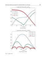
The increase in capacity of the APC scheme as compared to the conventional ANF scheme
is demonstrated in Fig. 8. The capacity of the APC scheme significantly outperforms the
conventional ANF protocols due to the relay’s full duplex capability. For polarized ANF, the
use of dual polarized antenna at the destination node provides a marginal increase in capacity.
Therefore, even if polarized antennas are also used, the APC scheme has a significant capacity
advantage over the polarized ANF scheme. The APC scheme without cross-polarization has
slightly less capacity than the APC system with cross-polarization but still it is higher than the
ANF systems.
The BER performance comparison among the SISO, ANF protocol, and the APC system is
presented in Fig. 9. The APC system without cross-polarization has a gain of about 4.5dB
over the conventional ANF protocol at BER 10
−3
.Thusthecostofusingdualpolarized
antennas and separate RF chains at the relay node is justified by the significantly lowered
BER. With the presence of cross-polarization, the performance further improves because
41
Asynchronous Cooperative Protocols for Inter-vehicle Communications
0 5 10 15 20 25 30 35 40
0
2
4
6
8
10
12
14
Normalized γ
sd
(dB)
Ergodic Capacity (bps/Hz)
ANF scheme
Polarized ANF scheme with cross−pol
APC scheme without cross−pol
APC scheme with cross−pol
Fig. 8. Capacity comparison of one relay APC scheme.
polarization diversity can be achieved. The polarized ANF also has a marked improvement,
but is approximately 3dB worse than the APC scheme. Another observation is the differences
in the asymptotic slope of SISO to the APC scheme. It verifies that diversity is achieved for
cooperative schemes with and without cross-polarization.
0 5 10 15 20
10
−6
10
−5
10
−4
10
−3
10
−2
10
−1
10
0
Normalized γ
sd
(dB)
BER
Non−cooperative scheme
ANF scheme without cross−pol
ANF scheme with cross−pol
APC scheme without cross−pol
APC scheme with cross−pol
Fig. 9. BER performance of APC system.
As more RF front ends are installed in the APC scheme, the total energy required to achieve
a particular quality is compared with the conventional ANF and SISO schemes in Fig. 10. The
total energy consumption is calculated using (36), where E
s
is obtained using direct link SNR
γ
sd
observed at BER=10
−4
,whereγ
sd
= E
s
/N
0
. The direct link SNR is obtained by evaluating
the BER over 10,000 randomly generated channel samples at each transmission distance. It can
be observed that the APC scheme becomes more energy-efficient than both the ANF and SISO
protocols when d
sd
≥ 23m. The crossover point indicates the distance where the transmission
energy saving exceeds the extra circuit energy consumption in the APC scheme comparing
42
Advances in Vehicular Networking Technologies
to the SISO and ANF scheme. In addition, for practical applications, the source to destination
node speration will be mostly larger than 20m. Hence, the APC scheme will consume less
energy in realistic scenario.
10 20 30 40 50 60 70 80 90 100
10
−5
10
−4
10
−3
10
−2
10
−1
d
sd
(m)
Total energy consumption per bit in J
Non−cooperative scheme
ANF scheme
Pol−ANF scheme
APC scheme
Fig. 10. Total energy consumption per bit over
d
sd
when the relay node is located midway
between source and destination nodes.
5. Conclusion
In this chapter, we discuss some of the major asynchronous cooperative communication
protocols that can be used in vehicle-to-vehicle cooperative communications. The APC scheme
with full duplex relay that completes the data transmission between the source and the
destination in approximately same time duration as non-cooperative scheme is discussed in
detail. The performance improvement of APC scheme is demonstrated by the BER and the
capacity simulation results, which show its superiority over non-cooperative, conventional
and polarized ANF protocol. Even with the use of more RF front ends, the APC scheme has
less total energy consumption than ANF and non-cooperative schemes over more practical
distances between the nodes. Thus, the APC scheme is both spectral and energy efficient, and
is suitable for inter-vehicle cooperative communication.
6. References
Brennan, D. (Feb 2003). Linear diversity combining techniques, Proceedings of the IEEE
91(2): 331–356.
Cui, S., Goldsmith, A. & Bahai, A. (2003). Energy-constrained modulation optimization for
coded systems, pp. 372–376.
Cui, S., Goldsmith, A. & Bahai, A. (2004). Energy-efficiency of mimo and cooperative mimo
techniques in sensor networks, IEEE Journal on Selected Areas in Communications
22(6): 1089–1098.
Fitzek, F. & Katz, M. (2006). Cooperation in Wireless Networks: Principles and Applications,
Springers.
Haykin, S. & Moher, M. (2004). Modern Wireless Communications, Prentice Hall.
43
Asynchronous Cooperative Protocols for Inter-vehicle Communications
Laneman, J. N., Tse, D. & Wornell, G. (2004). Cooperative diversity in wireless networks:
Efficient protocols and outage behavior, IEEE Transactions on Information Theory
50(12): 3062–3080.
Matolak, D. W., Sen, I. & Xiong, W. (2006). Channel modeling for V2V communications, Proc.
Third Annual International Conference on Mobile and Ubiquitous Systems: Networking and
Services.
Peters, S. & Heath, R. W. (2008). Nonregenerative MIMO relaying with optimal transmit
antenna selection, IEEE Signal Processing Letters 15: 421 –424.
Sohaib, S. & So, D. K. C. (2009). Asynchronous polarized cooperative MIMO communication,
Proc. IEEE 69th Vehicular Technology Conference pp. 1–5.
Sohaib, S. & So, D. K. C. (2010). Energy analysis of asynchronous polarized cooperative MIMO
protocol, Proc. IEEE 21st Personal, Indoor and Mobile Radio Communications Symposium.
Sohaib, S., So, D. K. C. & Ahmed, J. (2009). Power allocation for efficient cooperative
communication, Proc. IEEE 20th Personal, Indoor and Mobile Radio Communications
Symposium.
Tang, X. & Hua, Y. (2007). Optimal design of non-regenerative MIMO wireless relays, IEEE
Transactions on Wireless Communications 6(4): 1398 –1407.
Wang, D. & Fu, S. (2007). Asynchronous cooperative communications with STBC coded single
carrier block transmission, Proc. IEEE Global Telecommunications Conference pp. 2987
–2991.
Wei, S., Goeckel, D. L. & Valenti, M. (2006). Asynchronous cooperative diversity, IEEE
Transactions on Wireless Communications 5(6): 1547 – 1557.
44
Advances in Vehicular Networking Technologies
Boto Bako and Michael Weber
Institute of Media Informatics, Ulm University
Germany
1. Introduction
Vehicular ad-hoc networks (VANETs) enable promising new possibilities to enhance traffic
safety and efficiency. The vision of VANETs is that vehicles communicate spontaneously,
in an ad-hoc manner over a wireless medium. Based on this inter-vehicle communication
(IVC), vehicles exchange important information, e.g., about road conditions and hazardous
situations. Moreover, such information can be propagated via multiple hops, thus making the
dissemination of important information possible over longer distances.
This is the key advantage of this kind of safety applications compared to conventional safety
systems. Whereas conventional safety systems only rely on information sensed in the direct
neighborhood by onboard sensors of a vehicle, active safety applications based on IVC can
utilize information generated by nodes multiple hops away. Moreover, such information can
be enriched on the way with information sensed by relaying cars. This greatly enhances the
potential of VANET applications. The advantage is twofold:
• Having information about distant hazardous situations like an accident ahead or icy road,
the driver can be warned in-time, thus being able to completely avoid the dangerous
situation.
• Aggregating information from multiple cars enables retaining information on a higher
semantic level. This way, applications like cooperative traffic jam warning and cooperative
parking place detection can be realized.
The enabling technology for such applications is the wireless ad-hoc communication between
vehicles. Especially the dissemination of messages in a specific geographic region represents a
fundamental service in VANETs to which we refer to as geographic broadcast (GeoCast). This
communication paradigm is used by many applications to enhance traffic safety and efficiency
but it can also serve as a basic mechanism for other routing protocols. Because of its relevance
in the domain of vehicular networks, it is of key importance that the communication protocol
enables efficient message dissemination.
The realization of a robust and efficient broadcast mechanism is a challenging task due to
the wide range of applications envisioned to build upon this communication technology,
the rigorous requirements of safety applications, and the special network characteristics
of vehicular networks. Therefore, the main focus of this chapter is the efficient broadcast
of information for VANET applications. We want to give a broad and in-depth review of
recent research in this topic and present simulation results of efficient dissemination protocols
designed for such applications.
This chapter is organized as follows: In Section 2 we discuss briefly different types of
VANET applications, followed by an overview of different communication mechanisms
Efficient Information Dissemination in VANETs
3