Advances in Vehicular Networking Technologies Part 14 ppt
Bạn đang xem bản rút gọn của tài liệu. Xem và tải ngay bản đầy đủ của tài liệu tại đây (1.4 MB, 30 trang )
Advances in Vehicular Networking Technologies
382
As shown in Fig.18, we make
in
SINR vary from -10dB to 30dB, and
out
SNR grows slowly with
the increase of
in
SINR . One reason is that the output SNR by ICA algorithm is affected by
the mutual information among the source signals and the probability distribution of each
signal. For such characteristics are determined, the limited change of
in
SINR plays a little
effect in
out
SNR .When
in
SNR is equal to 40dB,
out
SNR is around from 18dB to 22dB. But when
in
SNR is equal to 10dB,
out
SNR is around from 9dB to 14dB. Based on this analysis, it can be
found that by means of ICA algorithm, the higher
in
SNR is, the higher
out
SNR is.
-10 -5 0 5 10 15 20 25 30
0
5
10
15
20
25
30
Input signal-to-intererence-noise ratio (dB)
Output signal-to-noise ratio (dB)
Max-SINR ICA,(SNR)in=40dB
Fast ICA,(SNR)in=40dB
Max-SINR ICA,(SNR)in=10dB
Fast ICA,(SNR)in=10dB
Region 1: performance improvement
Region 2: performance degradation
threshold
Fig. 18.
out
SNR and
in
SINR (fix the length of processing frame)
On the other side, with the same condition, such as
in
SNR is equal, the Max-SINR ICA
algorithm shows a better performance than the Fast ICA algorithm. Especially,
out
SNR improved by the Max-SINR ICA algorithm is a little more than
out
SNR improved by
the Fast ICA algorithm.
However, with the increase of
in
SINR , the increase of
out
SNR is still limited, whose growth
rate is slower than
in
SINR . As a result, when
in
SINR increases into some value, it reaches to
balance:
out in
SNR SINR= . Moreover, this state is shown as the slash through the origin in
Fig.18, which divides the graph into two regions: Region 1 and Region 2.
In Region 1,
out in
SNR SINR> , which means that the interference mitigation by ICA algorithm
is effective. But in Region 2,
out in
SNR SINR< , which means that the interference mitigation
by ICA algorithm is not only ineffective, but also degrades the performance worse as the
growth of
in
SINR .
Compared with the Fast ICA algorithm, the Max-SINR ICA algorithm raises the threshold
in
SINR of Region 1 and Region 2. It can be seen in Fig.18 that the threshold
in
SINR for the
Max-SINR algorithm is a little larger, which means if
in
SINR is in this area, the performance
is improved by the Max-SINR ICA algorithm, but degraded by the Fast ICA algorithm.
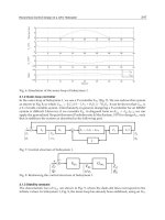
Fig. 19 shows the processing gain for such two ICA algorithms, when the length of
processing frame is fixed. It can be found that the processing gain decreases with the
increase of
in
SINR . Besides, as
in
SINR continuously increases, we can set the area with the
positive processing gain as Region 1, while the area with the negative processing gain as
Region 2. Among Region 1 and Region 2 is the threshold line.
Inter-cell Interference Mitigation for Mobile Communication System
383
-10 -5 0 5 10 15 20 25 30
-20
-15
-10
-5
0
5
10
15
20
25
30
Input signal-to-intererence-noise ratio (dB)
Processing gain (dB)
Max-SINR ICA,(SNR)in=40dB
Fast ICA,(SNR)in=40dB
Max-SINR ICA,(SNR)in=10dB
Fast ICA,(SNR)in=10dB
Region 1: performance improvement
Region 2: performance degradation
threshold
Fig. 19. Processing gain (fix the length of processing frame)
Specially, when
in
SINR is lower than the threshold, the processing gain is positive, which
enables to improve the performance. What’s important, the lower the
in
SINR is, the higher
the processing gain is, which is useful to the users in cell-edge. But when
in
SINR is higher
than the threshold, the processing gain is negative, which degrades the performance.
Compared with the performance brought by such two algorithms, the processing gain
brought by the Max-SINR ICA algorithm is larger with the same
in
SNR . Moreover, the
introduced algorithm also raises the threshold
in
SINR . When
in
SINR is among this area, the
processing gain can be improved by the Max-SINR ICA algorithm, but degraded by the Fast
ICA algorithm.
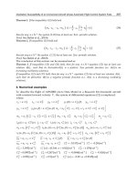
4.3.3 Fix the strength of thermal noise
In order to measure the effects brought by the length of processing frame, we fix the
strength of thermal noise in the mixed signals, which is in a form of fixed signal to noise
ratio,
in
SNR dB40= . Moreover, the simulation result is shown in Fig.20, and
out
SNR is also
set as a function of
in
SINR with different lengths of the processing frame.
In static simulation, we respectively take the length of the processing frame as 50 and 100,
and the performance brought by such two ICA algorithms is compared. Further, it can be
seen that the performance can be divided into two regions:
In Region 1, the performance is improved, where
out in
SNR SINR> . With the increase
of
in
SINR , it shows that for the same ICA algorithm, the longer the length of the processing
frame is, the higher the
out
SNR is. The reason is that the independence among source signals
is easier to be established with longer processing frames. But in Region 2, the performance is
degraded, where
out in
SNR SINR
<
, and it is degraded worse as
in
SINR increases gradually.
Moreover, when the length of the processing frame is longer, the threshold
in
SINR between
Region 1 and Region 2 also becomes a little higher.
The reason why Region 1 and Region 2 exist in Fig. 18 and Fig. 20 is that: The output SNR by
ICA algorithm is mainly affected by the mutual information among the source signals and
the probability distribution of each signal. Once such characteristics are determined in the
Advances in Vehicular Networking Technologies
384
mixed signals, the limited change of
in
SINR plays a little effect in
out
SNR . At this time, as the
growth of
in
SINR ,
out
SNR increases slowly, such curve may gradually reach to the threshold.
Before this threshold, it’s Region 1. Else, it’s Region 2.
-10 -5 0 5 10 15 20 25 30
0
5
10
15
20
25
30
Input signal-to-intererence-noise ratio (dB)
Output signal-to-noise ratio (dB)
Max-SINR ICA,N=100
Fast ICA,N=100
Max-SINR ICA,N=50
Fast ICA,N=50
Region 1: performance improvement
Region 2: performance degradation
threshold
Fig. 20.
out
SNR and
in
SINR (fix the strength of thermal noise)
Compared with the Fast ICA algorithm, both
out
SNR
and the threshold
in
SINR
are raised by
the Max-SINR ICA algorithm, with the same processing frame. From Fig. 20, it can be seen
that in the threshold area, the performance is improved by the Max-SINR ICA algorithm,
but degraded by the Fast ICA algorithm.
-10 -5 0 5 10 15 20 25 30
-10
-5
0
5
10
15
20
25
30
35
Input signal-to-intererence-noise ratio (dB)
Processing gain (dB)
Max-SINR ICA,N=100
Fast ICA,N=100
Max-SINR ICA,N=50
Fast ICA,N=50
Region 2: performance degradation
Region 1: performance improvement
threshold
Fig. 21. Processing gain (fix the strength of thermal noise)
Fig.21 shows the processing gain for such two ICA algorithms, when the strength of thermal
noise is fixed. It can be found that the processing gain decreases with the increase of
in
SINR .
In Region 1, the processing gain is positive, and enables to improve the performance. While
Inter-cell Interference Mitigation for Mobile Communication System
385
in Region 2, the processing gain is negative, and degrades the performance. Similar to
Fig.19, it also can be found from Fig.21 that the longer the length of the processing frame is,
the higher the processing gain is.
Compared with the Fast ICA algorithm, both the processing gain and the threshold are
raised by the Max-SINR ICA algorithm with the same processing frame. The conventional
Fast ICA has forced the interference to zero, not considering the effect of the additive
thermal noise. Meanwhile, the introduced algorithm minimizes both the interference and
noise in order to maximize SINR. Thus the effect of the noise enhancement can be
suppressed by the introduced algorithm, which gives the performance improvement.
Based on the above analysis, it’s proper to use ICA algorithm under lower
in
SINR ,
higher
in
SNR and with longer lengths of the processing frame, which enables to mitigate the
inter-cell interference, and improve the performance. Specially, it had better employ such
inter-cell interference algorithm in practical application when the range of
in
SINR is below
10dB, but
in
SNR is above 10dB.
On the other side, it is worth noting that the effect of user mobility isn’t considered because
of static simulation. Actually, when the length of processing frame is too large, such
mobility can’t be tracked for the Doppler frequency effect and time varying channel. In
practice, the length of processing frame should be limited by the maximum speed of UE,
which need to be researched by dynamic simulation in the future.
4.4 Summary
In order to cancel inter-cell interference, one inter-cell interference mitigation method is
introduced, which is based on ICA algorithm. Compared to finding the maximum kurtosis
in classical ICA algorithms, such as Fast ICA, Max-SINR ICA algorithm is introduced, which
sets SINR as the objective function in this algorithm. As an important measured factor in
interference mitigation, it need try to make such function get the maximum value. By
optimize the initial separation matrix in iterations, the convergence speed of this introduced
algorithm is faster than Fast ICA algorithm. Furthermore, two situations are divided in
simulation, which respectively fix the length of processing frame and fix the strength of
thermal noise.
By means of ICA algorithm, the output SNR increases as the growth of the input SINR, but
the processing gain gradually decreases as the growth of the input SINR. Moreover, the
lower the SINR is, the higher the output SNR and the processing gain are.
On the other side, as the growth of the input SINR, there are two regions for the
performance. When the input SINR is lower than the threshold, the performance is
improved. But when the input SINR is higher than the threshold, the performance is
degraded.
Besides, the effects brought by the thermal noise and the length of the processing frame are
considered. When the input SNR is higher in the mixed signals, the output SNR is higher.
When the length of the processing frame is longer, the output SNR is also higher. What’s
more, compared with the Fast ICA algorithm, the Max-SINR algorithm raises the output
SNR and the processing gain in the same conditions.
According to the above comparison, it can be found that this inter-cell interference
cancellation method is performed well with lower SINR. So it’s good to improve the quality
of service for users in cell-edge where is always in the state of lower SINR. Another
advantage is that this algorithm can be performed in a semi-blind state, with no precise
knowledge of source signal and channel information. Moreover, it may not bring with extra
Advances in Vehicular Networking Technologies
386
interference, which is much better than many existing inter-cell interference cancellation
algorithms.
5. Conclusion
In this chapter, the inter-cell interference mitigation for mobile communication system is
analyzed and three kinds of solutions with inter-cell interference coordination, inter-cell
interference prediction and inter-cell interference cancellation are introduced with system
models, theoretical analyses and simulation results.
For interference coordination, Soft Fractional Frequency Reuse and Coordination Frequency
Reuse schemes are introduced. Their frequency reuse factors are derived. Simulation results
are provided to show the throughputs in cell-edge are efficiently improved compared with
soft frequency reuse scheme.
The inter-cell interference prediction is an active interference mitigation method. The
theoretical basis, which is the optimal estimation theory, is provided with including of two
parts: time series and the optimal filter estimation. Besides, the steps of Box-Jenkins method
are introduced in addition. The reliability is also analyzed by means of prediction accuracy,
which is based on the relationship of the coherent time and the time delay.
For inter-cell interference cancellation, two major technologies are described in this chapter,
which are space interference suppression and interference reconstruction/subtraction
respectively. Based on the independent component analysis (ICA) technology in blind
source separation, a semi-blind interference cancellation algorithm is introduced, named as
Max-SINR ICA, which aims to improve the output SNR and optimize the initial iterative
separation matrix. Simulation results show that the iterative convergence speed for Max-
SINR ICA algorithm is faster than the traditional Fast-ICA algorithm. By the Max-SINR ICA
algorithm, the inter-cell interference can be efficiently cancelled in a semi-blind state,
especially with lower input SINR, higher input SNR and longer processing frame.
6. References
3GPP. (2005). R1-050507, Soft frequency reuse scheme for UTRAN LTE, Huawei. 3GPP TSG
RAN WG1 Meeting #41, Athens, Greece.
3GPP. (2005). R1-051396. Comparison of bit repetition and symbol repetition for inter-cell
interference mitigation.
3GPP. (2006). R1-060416. Combining inter-cell-interference co-ordination/avoidance with
cancellation in downlink and TP.
3GPP. (2006). R1-060518. TP for combining beam-forming with other inter-cell interference
mitigation approaches.
3GPP. (2006). TR 25.814 v7.1.0, Physical layer aspects for evolved UTRA (Release 7).
3GPP. (2006). TR 25.913, Requirements for Evolved UTRA (E-UTRA) and Evolved UTRAN
(E-UTRAN).
3GPP. (2007). TR 25.912. Feasibility Study for Evolved UTRA and UTRAN.
3GPP. (2008). R1-082024, A discussion on some technology components for LTE-Advanced,
Ericsson. 3GPP TSGRAN WG1 #53, Kansas City, MO, USA.
3GPP. (2008). R1-083569, Further discussion on Inter-Cell Interference Mitigation through
Limited Coordination, Samsung. 3GPP TSGRAN WG1 #54bits, Prague, Czech
Republic.
Inter-cell Interference Mitigation for Mobile Communication System
387
3GPP. (2009). R1-091688, Potential gain of DL CoMP with joint transmission, NEC Group.
3GPP TSGRAN WG1 #57, San Francisco, USA.
3GPP. (2009).TR 36.814 v1.0.1, Further Advancements for E-UTRA Physical Layer Aspects
(Release 9).
A. Hyvarienen, J. Karhunen, E. Oja. (2001). Independent Component Analysis, John Wiley
and Sons.
Haipeng Le, Lei Zhang, Xin Zhang, and Dacheng Yang. (2007).A Novel Multi-Cell OFDMA
System Structure using Fractional Frequency Reuse, In Proc. of IEEE PIMRC 2007,
pp.1-5.
Hanbyul Seo and Byeong Gi Lee. (2004). A proportional-fair power allocation scheme for
fair and efficient multiuser OFDM systems, In Proc. of IEEE Globecom ’04 ,vol.6,
pp.3737-3741.
H.L. Bertoni. (2000). Radio propagation for modern wireless systems. Prentice Hall, Inc.
Huiling Jia, Zhaoyang Zhang, Guanding Yu, Peng Cheng, and Shiju Li. (2007).On the
Performance of IEEE 802.16 OFDMA System under Different Frequency Reuse and
Subcarrier Permutation Patterns, In Proc. of IEEE International conference on
communications, ICC 07’, pp.5720-5725.
Hui Zhang, Xiaodong Xu, Xiaofeng Tao, Ping Zhang. (2009). An Inter-Cell Interference
Mitigation Method for OFDM-Based Cellular Systems Using Independent
Component Analysis. IEICE Transactions on Communications, Vol.E92-B, No.10.
Hui Zhang, Xiaodong Xu, Jingya Li, Xiaofeng Tao. (2009). Multicell Power Allocation
Method based on Game Theory for Inter-Cell Interference Coordination. Science in
China, Series F: Information Sciences, Vol.52, No.12, pp: 2378-2384.
Hui Zhang, Jingya Li, Xiaodong Xu, Shuang Wang, Ping Zhang. (2009). Multi-cell Subcarrier
Allocation based on Interference Forecast by Kalman Filter. Journal of Beijing
University of Posts and Telecommunications, Vol.32, No.3, pp.86-90.
Hui Zhang, Xiaodong Xu, Jingya Li, and Xiaofeng Tao.(2010) Subcarrier Resource
Optimization for Cooperated Multipoint Transmission. International Journal of
Distributed Sensor Networks, vol. 2010.
Hui Zhang, Jingya Li, Xiaodong Xu, Tommy Svensson. (2009). Channel Allocation based on
Kalman Filter Prediction in Downlink OFDMA Systems. IEEE VTC 2009-Fall.
Hyvarinen, A. (1999). Fast and robust fixed-point algorithms for independent component
analysis. IEEE Trans. on Neural Networks, vol.10, no. 3, pp. 626 - 634.
I. Kostanic, W. Mikhael. (2002).Rejection of the co-channel interference using non-coherent
independent component analysis based receiver, Proc. IEEE Midwest Symposium on
Circuits and Systems, vol. 2, Aug.2002.
I.Kostanic, W.Mikhael. (2004).Blind source separation technique for reduction of co-channel
interference. IEE Electronics Letters, Vol. 38, No. 20, pp.1210 – 1211.
J.G.Andrews. (2005). Interference cancellation for cellular systems: a contemporary
overview. IEEE Wireless Commun. Magazine, vol.12, no. 2, pp. 19 - 29.
J. Tomcik. (2006). Qualcomm, MBFDD and MB TDD wideband mode, IEEE 802.20-05/68r1.
K.N. Lau, K. Yu, K. Ricky.(2006). Channel adaptive technologies and cross layer designs for
wireless systems with multiple antennas theory and applications. Canada: John
Wiley & Sons, Inc., Publication, pp. 1-503.
K.I. Lee, Y.H. Ko. (2006). An inter-cell interference cancellation method for OFDM cellular
systems using a subcarrier-based virtual MIMO. Proc. IEEE VTC, pp. 1-5.
Advances in Vehicular Networking Technologies
388
Ki Tae Kim, Seong Keun Oh. (2007).A Universal Frequency Reuse System in a Mobile
Cellular Environment, In Proc. of IEEE VTC 2007-Spring, pp.2855-2859.
Ki Tae Kim, Seong Keun Oh. (2008).An Incremental Frequency Reuse Scheme for an
OFDMA Cellular System and Its Performance, In Proc. of IEEE VTC 2008-Spring,
pp.1504-1508.
K.W. Park, K.I. Lee, Y.S. Cho. (2006). An inter-cell interference cancellation method for
OFDM-Based cellular systems using a virtual smart antenna. IEICE Trans. on
Commun., vol. E89-B, no.1, pp. 217-219.
L. Prarra, P. Sajda.(2003). Blind source separation via generalized eigenvalue decomposition.
Journal of Machine Learning Research, no.4, pp. 1261-1269.
M. Barkat. (2005). Signal Detection and Estimation. Artech House Publishers.
Q.H. Spencer, C.B. Peel. (2004). An introduction to the multi-user MIMO downlink. IEEE
Commun. Magazine, vol.42, pp. 60-67.
S.E. Elayoubi, O. B. Haddada, and B. Fourestie. (2008). Performance Evaluation of
Frequency Planning Schemes in OFDMA-based Networks, IEEE Trans. Wireless
Commun., vol. 7, no.5, pp. 1623–1633.
S.R. Curnew, J. How. (2007). Blind signal separation in MIMO OFDM systems using ICA
and fractional sampling. Proc. International Symposium on Signals, Systems and
Electronics, pp. 67-70.
T. Ristaniemi, J. Joutsensalo. (1999). Nonlinear algorithm for blind interference cancellation,
Proc. IEEE Signal Processing Workshop on Higher-Order Statistics, pp.43-47.
T. Yang. (2004). Diversity wireless receivers with efficient co-channel interference
suppression. Proc. IEEE Advances in Wired and Wireless Communication, pp.145-147.
Xu Fangmin, Tao Xiaofeng, Zhang Ping. (2009). A Frequency Reuse Scheme for OFDMA
Systems, Journal of Electronics&Information Technology,vol. 3, no.4, pp.903-906.
Xu Xiaodong, Zhang Hui, Li Jingya, Tao Xiaofeng, Zhang Ping. (2009). An Improved
Exponential Distributed Power Control Algorithm for MIMO Cellular Systems.
IEEE WiCOM 2009.
1. Introduction
The latest advancements of the 3
rd
generation (3G) universal mobile telecommunications
system (UMTS) have led to the long term evolution (LTE) standard release (referred to as 3.9G)
within the 3
rd
generation partnership project (3GPP). LTE does not meet the requirements
for the fourth generation (4G) systems defined by the international telecommunication union
(ITU). Therefore, work on LTE-Advanced within 3GPP has recently started. LTE-Advanced
can be seen as the continuous evolution of wireless service provision beyond voice calls
towards a true ubiquitous air-interface capable of supporting multimedia services (Sesia et al.,
2009).
LTE-Advanced systems face a number of essential requirements and challenges which include
coping with limited radio resources, increased user demand for higher data rates, asymmetric
traffic, interference-limited transmission, while at the same time the the energy consumption
of wireless systems should be reduced. Driven by the ever-growing demand for higher data
rates to effectively use the mobile Internet, future applications are expected to generate a
significant amount of both downlink (DL) and uplink (UL) traffic which requires continuous
connectivity with quite diverse quality of service requirements. Given limited radio resources
and various propagation environments, voice over IP applications, such as Skype, and
self-generated multimedia content platforms, such as YouTube, and Facebook, are popular
examples that impose a major challenge on the design of LTE-Advanced wireless systems.
One of the latest studies from ABI Research, a market intelligence company specializing
in global connectivity and emerging technology, shows that in 2008 the mobile data traffic
around the world reached 1.3 Exabytes (10
18
). By 2014, the study expected the amount to reach
19.2 Exabytes. Furthermore, it has been shown that video streaming is one of the dominating
application areas which will grow significantly (Gallen, 2009).
In order to meet such diverse requirements, especially, the ever-growing demand for mobile
data, a number of different technologies have been adopted within the LTE-Advanced
framework. These include smart antenna (SA)-based (also known as directional antennas
or antenna arrays) multiple-input multiple-output (MIMO) systems (Bauch & Dietl, 2008a;b;
Foschini & Gans, 1998; Kusume et al., 2007) and efficient multiuser transmission techniques
such as multiuser MIMO using precoding to achieve, for example, space division multiple
access (SDMA) (Fuchs, et al., 2007), and networked MIMO, i.e. coordinated multipoint (CoMP)
systems. Therefore, there is a broad agreement recently among LTE standardization groups
Rami Abu-alhiga
1
and Harald Haas
2
The University of Edinburgh
United Kingdom
Novel Co-Channel Interference Signalling
for User Scheduling in Cellular
SDMA-TDD Networks
21
that MIMO will be the key to achieve the promised data rates of 1 Gbps and more (Seidel,
2008).
It is well known that co-channel interference (CCI), caused by frequency reuse, is considered
as one of the major impairments that limits the performance of current and 4G wireless
systems (Haas & McLaughlin, 2008). To outmaneuver such obstacle, various techniques
such as joint detection, interference cancelation, and interference management have been
proposed. One of the most promising technology is to utilize the adaptability of SAs. Spatial
signal pre-processing along with SAs can provide much more efficient reuse of the available
spectrum and, hence, an improvement in the overall system capacity. This gain is achievable
by adaptively utilizing directional transmission and reception at the base station (BS) in order
to enhance coverage and mitigate CCI. One of the key challenges to overcome, however, is the
signalling overhead which increases drastically in MIMO systems.
Unlike the traditional resource allocation in single-input single-output (SISO) fading channels,
which is performed in time and frequency domains, the resources in MIMO systems are
usually allocated among the antennas (the spatial domain). From closed-loop MIMO point
of view, channel aware adaptive resource allocation has been shown to maintain higher
system capacity compared to fixed resource allocation (Ali et al., 2007; Gesbert et al., 2007;
Koutsimanis & Fodor, 2008). In particular, adaptive resource allocation is becoming more
critical with scarce resources and ever-increased demand for high data rates.
It is shown that for closed-loop MIMO the optimal power allocation among multiple
transmit antennas is achieved through the water-filling algorithm (Telatar, 1999). However,
to enable optimal power allocation, perfect channel state information (CSI) at the transmitter
is required. Some other work focused on transmit beamforming and precoding with limited
feedback (Love, et al., 2005; 2003; Mukkavilli et al., 2002; 2003; Zhou et al., 2005), where the
transmitter uses a quantized CSI feedback to adjust the power and phases of the transmitted
signals. To further reduce the amount of feedback and complexity, different strategies such
as per-antenna rate (an adaptive modulation and coding approach that controls each antenna
separately) and power control algorithms have been proposed (Catreux et al., 2002; Chung
et al., 2001a;b; Zhou & Vucetic, 2004; Zhuang et al., 2003). By adapting the rate and power
for each antenna separately, the performance (error probability (Gorokhov et al., 2003) or
throughput (Gore et al., 2002; Gore & Paulraj, 2002; Molisch et al., 2001; Zhou et al., 2004))
can be improved greatly at the cost of slightly increased complexity. Additionally, antenna
selection is proposed to reduce the number of the spatial streams and the receiver complexity
as well. Various criteria for receive antenna selection or transmit antenna selection are
presented, aiming at minimizing the error probability (Bahceci et al., 2003; Ghrayeb & Duman,
2002; Gore et al., 2002; Gore & Paulraj, 2002; Heath & Paulraj, 2001; Molisch et al., 2003) or
maximizing the capacity bounds (Molisch et al., 2003; Zhou & Vucetic, 2004). It is shown that
only a small performance loss is experienced when the transmitter/receiver selects a good
subset of the available antennas based on the instantaneous CSI (Zhou et al., 2004). However,
it is found that in spatially correlated scenarios, proper transmit antenna selection cannot
just be used to decrease the number of spatial streams, but can also be used as an effective
means to achieve multiple antenna diversity (Heath & Paulraj, 2001). When the channel links
exhibit spatial correlation (due to the lack of spacing between antennas or the existence of
small angular spread), the degrees of freedom (DoF) of the channel are usually less than the
number of transmit antennas. Therefore, using transmit antenna selection, the resources are
allocated only to the uncorrelated spatial streams so that an enhanced capacity gain can be
achieved.
390
Advances in Vehicular Networking Technologies
Most of the above work focused on the point-to-point (P2P) link in single user scenario. In a
multiuser MIMO (MU-MIMO) context, MIMO communication can offer significant capacity
growth by exploiting spatial multiplexing and multiuser scheduling. Therefore, opportunistic
approaches have recently attracted considerable attention (Choi et al., 2006; Viswanath et al.,
2002). So far, opportunistic resource allocation in a MU-MIMO scenario is still an open
issue. Wong et al. and Dai et al. (Dai et al., 2004; Wong et al., 2003) consider a multiuser
MIMO system and focused on multiuser precoding and turbo space-time multiuser detection,
respectively. More recent work has addressed the issue of cross-layer resource allocation in DL
MU-MIMO systems (Wang & Murch, 2005). In broadcast MU-MIMO channels, dirty-paper
coding (DPC) (Costa, 1983) can achieve the maximum throughput (Goldsmith et al., 2003;
Vishwanath et al., 2003; Weingarten et al., 2004). In particular, DPC can accomplish this
by using successive interference precancelation through employing complex encoding and
decoding. Unfortunately, DPC is classified as a nonlinear technique that has very high
complexity and is impractical. Due to the fact that DPC is computationally expensive for
practical implementations, its contribution is primarily to determine the achievable capacity
region of MU-MIMO channel under a per-cell equal power constraint. Therefore, many
alternative practical precoding approaches are proposed to offer a trade-off complexity for
performance (Airy et al., 2006; Chae et al., 2006; Hochwald et al., 2005; Pan et al., 2004; Shen
et al., 2005; Windpassinger et al., 2004). These alternatives considered different criteria and
methods such as minimum mean squared error (MMSE) (Schubert & Boche, 2004; Shi et al.,
2008), channel decomposition, and zero forcing (ZF) (Chen et al., 2007; Choi & Murch, 2004;
Spencer et al., 2004; Wong et al., 2003).
One of the most attractive approaches is the block diagonalization (BD) algorithm which
supports orthogonal multiple spatial stream transmission. In BD algorithm, the precoding
matrix of each user is designed to lie in the null space of all remaining channels of other
in-cell users, and hence the intracell multiuser CCI is pre-eliminated (Chen et al., 2007; Shen
et al., 2005; Spencer et al., 2004). In particular, SA-based SDMA, implementing BD algorithm,
can multiplex users in the same radio frequency spectrum (i.e. same time-frequency resource)
within a cell by allocating the channel to spatially separable users. This can be done while
maintaining tolerable, almost negligible, intracell CCI enabled by BD signal pre-processing
capabilities. Moreover, channel aware adaptive SDMA scheme can be achieved through joint
exploitation of the spatial DoF represented by the excess number of SAs at the BS along with
multiuser diversity. Generally, the radio channel encountered by an array of antenna elements
is referred to as beam. In other words, SA technology along with BD algorithm can enable
the BS to adaptively steer multiple orthogonal beams to a group of spatially dispersed mobile
stations (MSs) (Choi et al., 2006), as depicted in Fig. 1.
The joint beam selection and user scheduling for orthogonal SDMA-TDD (time division
duplex) system is a key problem addressed in this chapter. From precoding point of view,
the availability of CSI of all in-cell users at the BS is crucial in multiuser (MU)-MIMO
communication scenario to optimally incorporate different precoding techniques such as BD,
adaptive beamforming, or antenna selection, in order to increase the overall system spectral
efficiency. Basically, there are two methods for providing a BS with CSI of all associated MSs,
namely limited (quantized) feedback and analog feedback. Limited feedback (also know as
direct feedback) involves the MS to measure the DL channel and to transmit a feedback
messages of quantized CSI reports to the BS during the UL transmission. Alternatively,
the second method, referred to as UL channel sounding according to LTE terminology,
involves the BS to estimate the DL channel based on channel response estimates obtained
391
Novel Co-Channel Interference Signalling for User Scheduling in Cellular SDMA-TDD Networks
MS1
Users
data
streams
UL channel sounding
MS2
MS3
MS4
BD
beam-
forming
Joint beam
and user
selection
Fig. 1. A block diagram of SA-based MU-MIMO transmission implementing BD
beamforming
from reference signals (pilots) received from the MS during UL transmission. Channel
sounding offers advantages in terms of overhead, complexity, estimation reliability, and delay.
Closed-loop SDMA-TDD networks can benefit from these advantages to avoid outdated
feedback scenarios, enhance the network throughput, and reduce the computational cost at
the user side. Clearly, TDD systems offer a straightforward way for the BS to acquire the
CSI enabled through channel reciprocity (Love, et al., 2004). The advantages of UL channel
sounding are discussed later in this chapter and a more detailed treatment can be found, for
instance, in the technical documents of the evolved universal terrestrial radio access (EUTRA)
study item launched in the LTE concept (Sesia et al., 2009).
In summary, UL channel sounding method is considered as one of the most promising
feedback methods for SA-based SDMA-TDD systems due to its bandwidth and delay
efficiency. In particular, UL channel sounding avoids the usage of dedicated feedback physical
channels which results in utilizing the available bandwidth for data transmission much more
effectively. In addition, UL channel sounding requires a shorter duration of time to convey the
feedback information to the BS compared to the direct feedback method. This feature reduces
the probability of having outdated feedback especially in fast varying channel conditions.
In interference-limited scenarios and according to Shannon capacity formula, the system
performance is limited by the CCI from adjacent cells. Meanwhile, conventional channel
sounding (CCS) only conveys the channel state information (CSI) of each active user to the
BS. Therefore, CSI is only a suboptimal metric for multiuser spatial multiplexing optimization
in interference-limited scenarios.
In light of the above, the benchmark system considered in this chapter for the system
level analysis of the feedback methodology is a closed-loop SDMA TDD system. In the
benchmark system, a BD technique is utilized to optimize the MU-MIMO spatial resources
allocation problem based on perfect instantaneous CSI of each in-cell active user obtained
from UL channel sounding pilots. The main goal of the benchmark system is to adaptively
communicate with a group of users over disjoint spatial streams while optimizing the gains
of the MU-MIMO channels. The optimization aims at enhancing the overall system capacity
using fixed and uniformly distributed transmit power.
Most of the ZF-based precoding algorithms (e.g. BD) have been designed to only mitigate
intracell CCI from different users in the same cell without considering CCI coming from
transmitters in neighbouring cells. In a cellular environment, especially when full frequency
reuse is considered, intercell (also known as other-cell) CCI becomes a key challenge which
cannot be eliminated by BD-like algorithms. Moreover, it is shown that intercell CCI can
significantly degrade the performance of SDMA systems (Blum, 2003). More specifically, if the
392
Advances in Vehicular Networking Technologies
BS schedules a group of users only based on the available CSI, the scheduling decision may be
optimum for a noise limited system, but high intercell CCI at the respective MSs might render
the scheduling decision greatly suboptimum. Therefore, the signal-to-interference-plus-noise
ratio (SINR) would be a more appropriate metric in multicell interference limited scenarios,
but this metric cannot directly be obtained from CCS. Thus, the key challenge here is to
provide knowledge of intercell CCI observed by each user to the BS in addition to CSI. If,
furthermore, intercell CCI observed by each SA at the BS itself is taken into account, the beam
selection and user scheduling process can be jointly improved for both DL and UL (Abualhiga
& Haas, 2008).
2. Contributions and assumptions
The contribution associated with the feedback-based interference management for SDMA
presented in this chapter can be split into three main parts:
• A novel interference feedback mechanism is developed. Specifically, it is proposed to
weight the UL channel sounding pilots by the level of the received intercell CCI at
each MS. The weighted uplink channel sounding pilots act as a bandwidth-efficient and
delay-efficient means for providing the BS with both CSI and intercell CCI experienced
at each active user. Such modification will compensate for the missing interference
knowledge at the BS when traditional UL channel sounding is used. In addition, through
exploitation of channel reciprocity the technique will act as implicit inter-cell interference
coordination (ICIC) avoiding any additional signalling between cells.
• A novel procedure is developed to make the interference-weighted channel sounding
(IWCS) pilots usable for the scheduler to optimize thespatial resource allocation during the
UL slot. It is proposed to divide the metric obtained from the IWCS pilots by the intercell
CCI experienced at the BS. The resulting new metric, which is implicitly dependent on DL
and UL intercell CCI, provides link-protection awareness and it is used to jointly improve
spectral efficiency in UL as well in DL.
• Finally, in order to facilitate a practical implementation, a heuristic algorithm (HA) is
proposed to reduce the computational complexity to solve user scheduling problem.
The key assumptions for the system level analysis of the IWCS pilots performance can be
summarized as follows:
• The considered closed-loop SDMA system enjoys perfect knowledge of the MIMO channel
coefficients of each active user. Hence, this channel knowledge at both BS and MS is
exploited to decompose the channel matrix into a collection of uncoupled parallel SISO
channels.
• The considered problem of jointly adapting the MU-MIMO link parameters for a set of flat
fading co-channel interfering MIMO links exploits two DoF: transmit antenna selection,
and user selection. Since these two DoF are associated with two different layers (the
physical (PHY) layer and medium access control (MAC) layer) the problem is considered
to be optimized in a cross-layer fashion.
• The time and frequency DoF (e.g. frequency channel dependent scheduling and dynamic
frequency resource allocation) are not considered in this study.
• This chapter assumes that appropriate methods are in place that completely eliminate
or avoid intracell CCI. Therefore, the system is only limited by intercell CCI. However,
393
Novel Co-Channel Interference Signalling for User Scheduling in Cellular SDMA-TDD Networks
the level of intercell CCI usually outweighs thermal noise and the system is, therefore,
interference limited.
• According to the definition of the UL channel sounding mechanism adopted by LTE,
channel sounding pilots are different from the demodulation pilots dedicated to the
process of coherent data detection. This implies that modifying the UL channel sounding
pilots does not hamper the channel estimation processes required for coherent data
detection. In particular, the only purpose of the proposed modification on the UL channel
sounding pilots is to add interference awareness to the channel sounding technique. In
addition, according to the LTE technical documents related to the UL channel sounding
pilots, the predetermined sounding waveforms are transmitted using orthogonal signals
among all active users in all cells using the same frequency band. The sounding pilot
sequences are chosen to be orthogonal in frequency domain among all of the users’
antennas (Sesia et al., 2009). In summary, the above properties enable the BS to estimate the
UL wideband channel for each antenna of each active user without any intracell or intercell
CCI between the channel sounding pilots. Moreover, errors in the channel estimation due
to the presence of noise is beyond the scope of this chapter. As a consequence, perfect
channel estimation is considered as outlined in the first assumption.
3. Overview of feedback methods
Basically, there are two methods for providing a BS with the CSI of all MSs, namely direct
feedback and UL channel sounding.
1. Direct feedback: According to LTE terminology this feedback method is termed
codebook-based feedback (Abe & Bauch, 2007). The MS determines the best entry in
a predefined codebook of precoding (beamforming) vectors/matrices and transmits a
feedback indication to the BS conveying the index value. In codebook feedback, the MS
uses downlink channel estimates to determine the best codebook weight or weights for
the BS to use as a precoding vector/matrix. The MS creates a feedback indication that
includes the codebook index and then sends the feedback indication to BS. This method can
be considered as a candidate option for frequency division duplex (FDD) systems which
require an explicit transfer of the DL CSI during the UL transmission due to the absence of
channel reciprocity.
It is worth mentioning that the physical feedback channel needs to have some reference
signals to facilitate the coherent detection of the feedback information at the BS.
2. UL channel sounding: The MS transmits a sounding waveform on the UL and the BS
estimates the UL channel of the MS from the received sounding waveform. The sounding
pilot sequences are chosen to be orthogonal between all of the users’ antennas and also are
designed to have a low peak to average power ratio (PAPR) in the time domain, (Fragouli,
et al., 2003; Popovic, 1992). The details of UL channel sounding are given in 3GPP technical
documents (Sesia et al., 2009). However, a brief treatment of the uplink channel sounding
signal model is given below.
According to LTE technical documents related to uplink channel sounding, the BS instructs
the MS where and how to sound (i.e., send a known pilot sequence) on the uplink. The
information obtained from uplink channel sounding at the BS is used to determine DL
beamforming weights for MIMO channel dependent scheduling on the uplink, as well as
for MIMO channel dependent scheduling on the DL. According to the structure discussed
394
Advances in Vehicular Networking Technologies
in 3GPP technical documents, channel sounding pilots enable the BS to estimate the UL
wideband channel for each antenna of each active user without any intracell or intercell
CCI between the channel sounding pilots.
Any codebook-based feedback scheme must account for the number of SAs at the BS. In a
codebook-based feedback scheme, the MS must be able to estimate the DL channel no matter
how many SAs are available at the BS. Thus, the computational complexity at the MS, and
the information that is required to be fed back increase with the number of antennas at BS.
In contrast, channel sounding schemes are independent of the number of BS antennas. In
other words, the problem of channel estimation is much more difficult in a codebook-based
feedback scheme than in a channel sounding scheme. More specifically, in codebook-based
feedback, the air-interface must enable the MS to estimate the channel between its antennas
and a relatively larger number of SAs at the BS. Such estimation imposes a heavy processing
load on a MS in a direct feedback scheme, while in a channel sounding scheme the estimation
process takes place at the BS side (Hassibi & Hochwald, 2003).
For instant, consider the case where the BS has eight transmit antennas and the MS has a two
receive antennas. In a channel sounding scheme, the BS must estimate the channel between
its eight antennas and the two transmit antennas. In contrast, in a codebook-based feedback
scheme, the air interface must enable the MS to estimate the channel between its two antennas
and the eight transmit antennas (an eight-source channel estimation problem, which is much
more difficult).
In TDD systems codebook-based feedback schemes tend to have much higher latency between
the time of the channel estimation and the time of the subsequent DL transmission. The
resulting outdated CSI can have detrimental effects on the performance of closed-loop
transmission schemes, especially in fast fading channels. In contrast, channel sounding
reference signals can be transmitted at the end of the UL slot. They can directly be exploited
for the subsequent DL transmission. For these reasons, in a TDD system, UL channel sounding
is preferred over codebook-based feedback.
4. SDMA with block diagonalization adaptive beamforming
4.1 Overview of SA technology
Originally, SA pre-processing techniques were proposed for military communications. Due to
the significant technological advancements over the past two decades, SA-based technologies
have become a cost-efficient solution for commercial communication systems to overcome
some of the major challenges such as multipath fading, CCI, and capacity limitations
especially for the cell-edge users. By exploiting the spatial diversity and the spatial processing
capabilities of SA, an efficient utilization of available bandwidth and, hence, an increased
system spectral efficiency is facilitated.
This section highlights the major features of SA-based SDMA systems relevant for the
main contributions in this chapter. More specifically, the review is aimed at the benchmark
SDMA system considered in this chapter. Also, this section briefly describes the generalized
BD beamforming method for multiuser SDMA system (Pan et al., 2004), where the BS
transmits multiple spatially multiplexed independent data streams to a group of users
selected according to a scheduling criterion. Due to physical size constraints at the user
side, the MSs are assumed to be equipped with limited number of multiple omnidirectional
antennas (OAs) (two throughout this chapter). This assumption is also convenient in order to
maintain affordable cost and reduced complexity at the mobile. As depicted in Fig. 2, each SA
395
Novel Co-Channel Interference Signalling for User Scheduling in Cellular SDMA-TDD Networks
Smart antenna
Fig. 2. A schematic illustration of a SA-based beamforming SDMA system
consists of an array of antenna elements and is dedicated to directionally transmit/recieve a
single independent spatial stream. Such spatial stream is referred to as an effective antenna
according to LTE terminology.
4.2 Multiuser MIMO BD system model
Consider a single-cell downlink MU-MIMO system where the BS is equipped with N
T
transmit SAs, and communicates over multiple MIMO channels with K users. It is assumed
that all users are equipped with the same number of receiving OAs denoted as N
R
. To simplify
the following analysis, it is assumed that N
R
< N
T
and N
T
is an integer multiple of N
R
in
order to serve all users. Fig. 3 illustrates an example of the considered SDMA system where
N
R
= 2.
MIMO
encoder
)(
1
tx
)(tx
MIMO
decoder
)(
1
1
ty
1,1
1
h
Data
sink
)(
1
ty
Data
Source
MIMO
decoder
Data
sink
)(t
K
y
2,1
1
h
1,1
K
h
)(
2
1
ty
)(
2
tx
)(tx
T
N
2,1
K
h
)(
1
ty
K
)(
2
ty
K
Fig. 3. SDMA system model with multiple MIMO users each equipped with 2 OAs
The flat fading MIMO channel matrix for user k is denoted as H
k
where h
(j,i)
k
is the fading
coefficient between the j
th
transmit antenna and the i
th
receive antenna of user k. For analytical
simplicity, the rank r
k
of H
k
is assumed to be equal to min(N
R
, N
T
) for all users. Again,
channel estimation errors caused by various reasons such as feedback delay, and feedback
quantization error, etc. are beyond the scope of this chapter. Hence, it is assumed that the BS
has perfect CSI for all users. By assuming that the number of data streams s
k
to user k is equal
to N
R
, the transmitted data streams to user k can be denoted as a N
R
-dimensional vector x
k
where
∑
K
k
=1
s
k
≤ N
T
. Since CSI is available at both sides of the MIMO link, it is assumed
that the MIMO transmission includes linear pre-processing and post-processing performed at
396
Advances in Vehicular Networking Technologies
both BS and MS, respectively. Prior to transmission, the data vector of user k, x
k
, is multiplied
by a N
T
× N
R
precoding matrix T
k
. In this chapter, it is assumed that T
k
is generated using
the BD beamforming algorithm which is a member of the zero-forcing (ZF) type multiuser
precoding algorithms (Spencer et al., 2004). At the BS, the data vectors of the K users are
linearly superimposed and propagated over the channel from all N
T
antennas simultaneously.
It is also assumed that the elements of x
k
are independent and identically distributed (i.i.d.)
with zero mean and unit variance. The signal vector received at user k is
y
k
= H
k
K
∑
ι=1
T
ι
x
ι
+ n
k
(1)
Equation (1) can be rewritten in the form of summation of the desired signal, the interference
signal, and the noise signal as follows
y
k
= H
k
T
k
x
k
+ H
k
K
∑
ι=k
T
ι
x
ι
+ n
k
(2)
where the first term on the right-hand-side of (2) is the desired signal, the second term denotes
the intracell CCI experienced by user k, and the last term n
k
is the additive white Gaussian
noise vector received by user k. According to key principles of BD algorithms, T
ι
is designed
such that H
k
T
ι
= 0 for ∀ι = k and , hence, the intracell CCI is completely eliminated (nulled).
The block matrices H
S
and T
S
can be defined as the system channel matrix and the system
precoding matrix, respectively, as follows:
H
S
=
H
H
1
H
H
2
H
H
K
H
(3)
T
S
=
[
T
1
T
2
T
K
]
(4)
Under the constraint of zero intracell CCI among users within the same cell, the optimal
solution can be obtained by diagonalizing the product of (3) and (4) H
S
T
S
. Now,
˜
H
S
can
be defined as the block matrix of the MIMO links interfering with user k as follows
˜
H
S
=
˜
H
H
1
˜
H
H
k
−1
˜
H
H
k
+1
˜
H
H
K
H
(5)
In light of the above, the intracell CCI free constraint requires that T
k
is selected to lie in
the null space of
˜
H
S
. The details of designing the BD precoding matrices and the associated
constraints can be found in (Chen et al., 2007; Pan et al., 2004; Spencer et al., 2004).
5. Problem statement
To fully exploit multiuser diversity the following questions have to be addressed. In a spatial
multiplexing opportunistic SDMA system with an excess number of SAs at the BS, how should
the optimal set of spatially separable users be chosen? What is the appropriate allocation
of the transmit/receive antennas (spatial beams) targeting the selected users? Since CCS
pilots only provide a sub-optimal metric (i.e. CSI), how can a better metric be provided (i.e.
instantaneous SINR) for such optimization problem while maintaining the same inherent
feedback bandwidth and delay efficiency? For practical reasons such as cost and physical
size, the number of SAs at the BS is greater than the number of OAs at the MS, as is the case
397
Novel Co-Channel Interference Signalling for User Scheduling in Cellular SDMA-TDD Networks
in EUTRA. Algorithms that achieve spatial multiplexing gains such as V-BLAST receivers
(Foschini, 1996), however, require that the number of antennas at the receiver is greater than
or equal to the number of transmit antennas. Consequently, the number of DL spatial streams
is limited by the number of OAs at the MS side. This situation results in a spatial DoF for the
selection of the subset of transmit SA for per user DL transmission.
Note that according to the fourth assumption in section 2, it is assumed that the BD algorithm
can only eliminate intracell CCI. However, the system is still limited by intercell CCI.
Therefore, throughout this chapter, whenever the term interference is mentioned, it refers to
CCI originated from transmitters in the adjacent cells.
6. Interference-aware metric for downlink optimization
In the following we make use of channel reciprocity which is best available in the TDD mode.
The new interference-weighted feedback concept proposed in this chapter is applied to the UL
CCS pilots. The first major contribution of this chapter is the use of modified pilots, termed UL
IWCS pilots, which are proposed to replace the UL CCS pilots. In particular, the CCS pilots are
modified to become IWCS pilots by weighting (dividing) the UL CCS pilots by the magnitude
of the intercell CCI received at each MS. The UL IWCS pilots are then used at the BS to extract
the CSI plus the level of the intercell CCI experienced by the respective MS. Thereby, the SINR
at each active MS is conveyed to the respective BS without any additional signalling overhead.
The key idea of applying the interference-weighting concept to the CCS pilots is depicted in
Fig. 4 for a SISO case.
Magnitude of pilot signal
UL CCS
P
UL IWCS
Other-cell CCI
at MS
DL
I
P
DL
I
Fig. 4. Interference-weighting concept applied to the pilot signal in a SISO case
Consider an UL CCS transmission of a SDMA cellular interference-limited scenario with a
BS equipped with N
BS
SAs and K active users, each equipped with N
MS
OAs. A narrowband
flat fading channel is assumed, i.e., a frequency subcarrier if orthogonal frequency division
multiple access (OFDMA) or single carrier frequency division multiple access is used. We
assume that both the BS and MSs experience sufficient local scattering. Therefore, both real
and imaginary parts of the entries of H
k
are samples of a zero-mean Gaussian distribution.
Hence, the conventional channel sounding MS-to-BS pilots transmission can be modeled as
follows:
y
u
(t)=H
k
(t)z
k
(t)+n
k
(t) (6)
where t is the time index. The predetermined pilot signal z
k
(t) is a N
MS
-dimensional vector;
the received signal y
k
(t) is a N
BS
-dimensional vector. Conventional channel sounding pilots
can be used to estimate two metrics: distance-dependent link gain (link budget), and the
398
Advances in Vehicular Networking Technologies
multipath fading channel coefficients (small-scale fading). By weighting (6) by the intercell
CCI experienced by user k in the downlink, the IWCS transmission can be written as follows:
y
k
(t)=
H
k
(t)z
k
(t)
I
DL
k
(t −1)
+
n(t) (7)
where
I
DL
k
(t − 1) is the amplitude of the intercell CCI experienced by k
th
MS at (t − 1)
th
time interval. Consequently, the interference-weighting concept enables the sounding pilots
to be used by the BS to obtain the DL interference-aware-metric O
DL−IAM
k
(t) ∈ C
N
BS
×N
MS
which can be formulated as follows
O
DL−IAM
k
(t)=
H
k
(t)
I
DL
k
(t −1)
(8)
From an information theoretic point of view, this metric (which can be considered as the
square root of the instantaneous MIMO DL signal-to-interference ratio (SIR)) provides better
feedback information compared to the CCS case. Consequently, the DL joint user scheduling
and transmit SA selection can be improved since the DL interference-aware-metric can be
used to obtain the SINR at the user side. Alternatively, quantized SINR can be fed back via the
direct feedback method, but this requires transmission resources and longer time (potentially
resulting in outdated feedback).
6.1 Interference estimation
From a practical point of view, the CCI experienced by a MS or a BS can be estimated by
allowing the respective entity to sense the channel when no intended transmission is taking
place. For instance, the CCI sensing period can be set for an active MS to be between the
end of the DL period and the beginning of the switching time (DL to UL). Then, the MS can
quantize the sensed CCI during the switching time period. Afterwards, a pilot weighted by
the quantized magnitude of CCI can be transmitted during the subsequent UL period. This
means that strong CCI will cause an ’artificial’ attenuation of the pilot signal. This will pretend
a bad channel at the BS, i.e the probability that the BS will schedule this particular resource
block for this MS is reduced.
6.2 Optimization methodology
The general approach used in this chapter to maximize the sum capacity is a brute-force
search. As in the example illustrated in Fig. 5, each BS, equipped with 4 SAs, will select 2
MSs each equipped with 2 OAs to access its spatial resources. Clearly, each MS experiences
independent levels of CCI, and is subject to independent channel conditions on the desired
link. For instance, the BS in cell 1 can schedule 2 users out of 3 possible candidates. For
any active user, a BS can assign 2 out of 4 SAs to establish communication links. Using
combinatorial basics, the BS has
(
3
2
)(
4
2
)
=
18 options to select antennas and user pairs in the
given example.
The procedure followed to extract the optimization metrics provided by IWCS pilots is
illustrated in the example depicted in Fig. 6 which is based on the example of Fig. 5. Basically,
each way in which the BS can distribute the 4 SAs among 2 out of 3 users forms a possible
solution. From Fig. 6, two arbitrary solutions are highlighted by shading them with squares of
different colors and different styles for the borderline. By considering the solution shaded by
blue squares of solid borderline, it can be seen that MS1 is allocated the first two SAs, while
399
Novel Co-Channel Interference Signalling for User Scheduling in Cellular SDMA-TDD Networks
Cell2Cell1
Interference link
Desired link
MS1
MS3
MS2
MS4
MS5
MS6
I
1
I
2
I
3
Fig. 5. Interference-limited multiuser MIMO system where each BS is equipped with 4
antennas, each MS is equipped with 2 antennas.
»
»
»
»
»
»
»
»
»
»
»
¼
º
«
«
«
«
«
«
«
«
«
«
«
¬
ª
¸
¸
¹
·
¨
¨
©
§
¸
¸
¹
·
¨
¨
©
§
¸
¸
¹
·
¨
¨
©
§
¸
¸
¹
·
¨
¨
©
§
¸
¸
¹
·
¨
¨
©
§
¸
¸
¹
·
¨
¨
©
§
¸
¸
¹
·
¨
¨
©
§
¸
¸
¹
·
¨
¨
©
§
¸
¸
¹
·
¨
¨
©
§
¸
¸
¹
·
¨
¨
©
§
¸
¸
¹
·
¨
¨
©
§
¸
¸
¹
·
¨
¨
©
§
¸
¸
¹
·
¨
¨
©
§
¸
¸
¹
·
¨
¨
©
§
¸
¸
¹
·
¨
¨
©
§
¸
¸
¹
·
¨
¨
©
§
¸
¸
¹
·
¨
¨
©
§
¸
¸
¹
·
¨
¨
©
§
¸
¸
¹
·
¨
¨
©
§
¸
¸
¹
·
¨
¨
©
§
¸
¸
¹
·
¨
¨
©
§
¸
¸
¹
·
¨
¨
©
§
¸
¸
¹
·
¨
¨
©
§
¸
¸
¹
·
¨
¨
©
§
3
)2,4(
3
3
)1,4(
3
2
)2,4(
2
2
)1,4(
2
1
)2,4(
1
1
)1,4(
1
3
)2,3(
3
3
)1,3(
3
2
)2,3(
2
2
)1,3(
2
1
)2,3(
1
1
)1,3(
1
3
)2,2(
3
3
)1,2(
3
2
)2
,2(
2
2
)1,2(
2
1
)2,2(
1
1
)1,2(
1
3
)2,1(
3
3
)1,1(
3
2
)2,1(
2
2
)1,1(
2
1
)2,1(
1
1
)1,1(
1
#4beam
B
S
#3beam
B
S
#2beam
B
S
#1beamBS
#2ant.
MS3
#1ant.
MS3
#2ant.
MS2
#1ant.
MS2
#2ant.
MS1
#1ant.
MS1
I
H
I
H
I
H
I
H
I
H
I
H
I
H
I
H
I
H
I
H
I
H
I
H
I
H
I
H
I
H
I
H
I
H
I
H
I
H
I
H
I
H
I
H
I
H
I
H
SVD
MS1
Eigen
values
?
MS3
Eigen
values
MS3
Metric
coefficient
MS1
Metric
coefficient
Fig. 6. Interference-limited virtual MU-MIMO matrix for the example illustrated in Fig. 5.
MS3 is allocated the last two antennas. Clearly, it can be seen that each SA allocation forms a
(2
×2) square matrix containing the coefficients of the optimization metric.
The next step is to obtain the eigenvalues of each square matrix via singular value
decomposition (SVD). Afterwards, the eigenvalues of each group of selected users are
summed. Finally, the summation of eigenvalues will be used to find the optimum solution
among all possible solutions according to the different scheduling criteria. To examine all
possible solutions, two approaches are considered: exhaustive search (ES) and HA. The details
of the two approaches are discussed in section 8.
7. Link-protection-aware metric for uplink and downlink optimization
The main purpose of this section is to propose a method to accommodate the IWCS pilots to
suit UL optimization. Since the amplitude of CCI experienced at the BS
I
UL
j
(t −1) (referred
to as UL interference) where (j
∈ 1, , N
BS
) is different from the CCI experienced at the MS
I
DL
k
(t − 1), the DL interference-aware-metric in (8) is not suitable for UL optimization. In
order to use the IWCS pilots for UL optimization, the BS weights each row of the metric
defined in (8) by the received interference at the associated SA
I
UL
j
(t −1) at the BS, which
is assumed to be known at the BS side. Thus, the new optimization metric, referred to as
400
Advances in Vehicular Networking Technologies
link-protection-aware-metric, O
LPAM
k
(t) ∈ C
1×N
MS
can be formulated as follows:
O
LPAM
k
(t)=
H
(j)
k
(t)
I
DL
k
(t −1)I
UL
j
(t −1)
(9)
where H
(j)
k
(t) is the j
th
row in H
k
(t).
Basically, this metric allows the BS to decide which subset of receive antennas it should use for
user k, and which users should be grouped together. Since the link-protection-aware-metric is
inversely proportional to
I
DL
k
(t − 1), a MS experiencing low interference level has higher
chances to be selected. Due to channel reciprocity, a user that receives little interference
from a set of users (in Tx mode) in a particular time slot, this user only causes little
interference to the same set of users (now in Rx mode) in a different time slot. Therefore,
the link-protection-aware-metric decreases the probability of scheduling users that are
potential strong interferers. Consequently, this forms an inherent link-protection for the
already established links in the neighboring cells. Similarly, this metric can be used for DL
optimization to jointly select a subset of users experiencing favorable channel conditions and
low intercell CCI to receive from a subset of SAs causing low intercell CCI to the neighboring
cells. Note that the link-protection-aware-metric is simultaneously used to improve both UL
and DL performance. Hence, the cross-layer scheduling for UL has to be the same as for DL,
which reduces the scheduling time.
According to the MIMO literature (Foschini & Gans, 1998; Telatar, 1999), if the channel matrix
H
k
is known at the BS, then the instantaneous DL MIMO channel capacity of user k using
fixed transmit power
P
t
N
BS
per antenna can be expressed as the sum of capacities of r SISO
channels each weighted with power gain λ
k
i
where (i ∈ 1, , r), r is the rank of the channel,
and λ
k
i
are the eigenvalues of H
k
H
H
k
. P
t
is the total transmit power at the BS. Assuming an
interference-limited system, the instantaneous MIMO capacity of user k can be expressed as
follows:
C
k
=
r
∑
i=1
log
2
(1 +
P
t
N
BS
×I
DL
k
2
λ
k
i
) (10)
By using the system model introduced above and (10), the primary objective is to find the
optimum way, according to the scheduling criterion in use, in which the BS distribute N
BS
antennas among
N
BS
N
MS
spatially separable users out of user population of size K, where a
selected user communicates with exactly N
MS
SAs at the BS. For instance, in the case of a
maximum sum rate scheduling criterion, the optimum solution maximizes the capacity of the
multiuser MIMO channel at the expense of fairness.
The sample-space population (SP) (the size of the pool containing all possible solutions) of
such problem is formulated later in this chapter. The resulting optimization problem can be
written as follows:
C
max
= argmax
v∈ SP
N
BS
N
MS
∑
k=1
C
v
k
(11)
where SP are all possible choices of allocating the beams to the members of v, while v
represents a possible choice of grouping the scheduled users.
401
Novel Co-Channel Interference Signalling for User Scheduling in Cellular SDMA-TDD Networks
7.1 Summary of the optimization metrics
In the DL, the following four metrics are used in conjunction with the different scheduling
criteria (section IV summarizes them):
1 The scheduler only uses perfect instantaneous measurements of the MIMO multipath
fading channel coefficients (ignoring the distance-dependent link-gain). This metric is fair
by nature due to the uniform distribution of the users and the i.i.d. distributed fading, and
it is referred to as DL blind-metric O
DL−BM
k
(t).
2 The scheduler uses instantaneous measurements of the distance-dependent link-gain. In
contrast, this metric is greedy by nature because it tends, in most of the cases, to select
those users which are closer to the BS, and it is referred to as DL link-gain-aware-metric
O
DL−LGAM
k
(t).
Note, the first two metrics above are supported by the conventional channel sounding
pilots and they do not provide the BS with information about interference at the mobile,
I
DL
k
(t −1).
3 The DL interference-aware-metric O
DL−IAM
k
(t) defined in (8) is used. This metric is
supported by the IWCS pilots or by means of explicit signalling which, however, requires
additional resources for signalling traffic.
4 To foster link-protection awareness the metric developed in (9), O
LPAM
k
(t), is used.
Two cases are examined for the UL:
1 The scheduler uses instantaneous measurements of the CSI of each spatial stream (each
row of H
k
) divided by the interference level experienced by the associated SA at the
BS. This metric, referred as UL interference-aware-metric, O
UL−IAM
k
(t) ∈ C
1×N
MS
can be
expressed as follows:
O
UL−IAM
k
(t)=
H
(j)
k
(t)
I
UL
j
(t −1)
(12)
It is important to mention that this metric can be obtained using UL CCS pilots since UL
interference
I
UL
j
(t −1) is available at the BS without feedback.
2 This is similar to the fourth case for the DL metrics which is defined as the
link-protection-aware-metric in (9). This metric jointly considers UL and DL performance.
In summary, the results shown in section 10 are associated with four different metrics for DL
transmission, and two different metrics for UL transmission.
7.2 Numerical example
To show the link-protection feature of the new metric defined in (9), a simple example is
presented in Fig. 7. In this example, the arbitrary numbers quantifying the gain of each link
and the interference experienced by each entity are used to estimate the achievable capacity
using (10). It is assumed that cell 2 has an established DL transmission with MS3 and the
argument for the achievable DL capacity is
H
MS3
I
MS3
=
9
3
. The neighboring BS, BS1, has got
assigned the same time slot for UL transmission and it attempts to select between MS1 and
MS2. If BS1 uses the UL interference-aware-metric, MS1 is scheduled for UL;
H
MS1
I
BS1
=
6
2
>
H
MS2
I
BS1
=
5
2
. Hence, the argument for the achievable UL capacity is
H
MS1
I
BS1
=
6
2
. As a result, it
is assumed that the interference at MS3 increases to I
MS3
= 4.5 due to the low shadowing
402
Advances in Vehicular Networking Technologies
MS1
MS2
BS1
MS3
BS2
MS4
Cell1
UL
Cell2
DL
I
BS1
=2
H
MS2
=5
H
MS1
=6
I
MS2
=0.5
I
MS1
=3
I
BS2
=2.5
I
MS3
=3
I
MS4
=3
H
MS3
=9
H
MS4
=6
High shadowing
H
i
g
h
s
h
a
d
o
w
i
n
g
Fig. 7. Example of interference-limited 2-cell scenario with which the basic working principle
of the link-protection-aware-metric is illustrated.
conditions between MS3 and MS1. This reduces the argument of the current achievable DL
capacity in cell 2 to
9
4.5
. Thus, the arguments of the achievable system capacity are
6
2
and
9
4.5
.
In contrast, if BS1 uses the link-protection-aware-metric, MS2 is scheduled;
H
MS1
I
MS1
×I
BS1
=
6
3×2
<
H
MS2
I
MS2
×I
BS1
=
5
0.5×2
. Hence, the argument of the achievable UL capacity is
H
MS1
I
BS1
=
5
2
.
Consequently, the interference at MS3 does not change (due to the high shadowing between
MS2 and MS3), and therefore, the arguments of the achievable cell capacity are
5
2
and
9
3
for
cell 1 and cell 2, respectively. In summary, in the first case the sum of the arguments of the
cell capacity is 5 whereas in the second case the sum is 5.5. Clearly, it can be seen from this
example that the link-protection-aware-metric used in the second case improves the overall
spectral efficiency.
8. Heuristic algorithm for reduced computational complexity
8.1 Introduction
Generally the ES is not practical due to its computational complexity. Therefore, in this section
a heuristic algorithm is proposed to reduce the involved complexity.
8.2 Exhaustive search mathematical model
The complexity of exhaustive search approach for scheduling optimization of SDMA system
depends on the total number of users K, the number of SAs at the BS N
BS
, and the number
of antennas at each MS N
MS
. The search burden for the scheduler is equivalent to the SP size.
Using combinatorial fundamentals, (13) and (14) can be obtained. By comparing (13) with (14),
it can be noticed that the multiuser diversity plays a significant role when K
>
N
BS
N
MS
; due the
fact that not all users can be scheduled.
If K
≤
N
BS
N
MS
SP =
N
BS
!
(
N
MS
!
)
K
(
N
BS
−KN
MS
)
!
SDMA DoF
; (13)
403
Novel Co-Channel Interference Signalling for User Scheduling in Cellular SDMA-TDD Networks
if K >
N
BS
N
MS
SP =
K!
N
BS
N
MS
!
K
−
N
BS
N
MS
!
Multiuser DoF
N
BS
!
(N
MS
!)
N
BS
N
MS
SDMA DoF
. (14)
It is important to mention that (13) and (14) are applicable only for scenarios in which N
BS
is
an integer multiple of N
MS
. To gain insight into the influence of each dimension of the DoF
on the SP, Fig. 8, Fig. 9(a), and Fig. 9(b) are obtained assuming N
MS
to be 2. By comparing
5
10
15
20
25
30
4
8
12
16
20
10
0
10
5
10
10
10
15
10
20
10
25
Number of users
Multiuser MIMO downlink scheduling optimization
Number of antennas at the BS
Sample−space population
2 antennas at each MS
4 antennas at each MS
Fig. 8. The search complexity versus the number of SAs at the BS and the number of users,
assuming 2 and 4 antennas at each MS
Fig. 9(a) with Fig. 9(b), it can be seen that SP grows polynomially with the number of users,
and exponentially with the number of antennas at the BS (Learned et al., 1997). Clearly, the ES
approach is computationally expensive for large number of users and antennas.
5 10 15 20 25 30
10
0
10
5
10
10
10
15
10
20
10
25
Number of users
Search space size
4 antennas at the BS
8 antennas at the BS
12 antennas at the BS
16 antennas at the BS
20 antennas at the BS
(a) Search space size versus the number of users
4 6 8 10 12 14 16 18 20
10
0
10
5
10
10
10
15
10
20
10
25
Number of antennas at the BS
Search space size
1 user
5 users
10 users
15 users
20 users
25 users
30 users
(b) Search size versus the number of SAs at the BS
Fig. 9. Search space size assuming 2 antennas at each MS
404
Advances in Vehicular Networking Technologies
8.3 Heuristic to reduce complexity
A HA is developed to significantly reduce the computational complexity of finding a close
to optimum solution. The algorithm exploits two basic principles. The first one is based
on the elimination of users that experience excessive interference while the second is based
on an angle of arrival (AoA) sectorization approach. The former aims to reduce the SP
by suppressing those users exposed to interference levels greater than a predetermined
interference threshold. The latter converts the cell of interest (CoI) optimization problem into
smaller optimization problems, which can be solved simultaneously. This can be done by
sectorizing the cell based on the AoA of the uplink channel sounding signal. Subsequently,
the antennas at the BS are distributed among these sectors according to the user density of
each sector. As a consequence, the original SP of the CoI will be reduced significantly as the
complexity is split into smaller parallel search spaces.
8.4 Numerical examples
To demonstrate the working mechanism of the HA, let us consider a cell with 28 users, each
equipped with 4 antennas, and the BS equipped with 16 antennas. According to (14), the
scheduler has to search through approximately 3.027
×10
9
possibilities to find the optimum
solution. By applying the interference based user elimination approach, let us assume that
8 users have been found to be exposed to severe interference levels. Similarly, assume that
the cell can be equally divided into four sectors with the same user density. According to the
proposed HA, the original optimization problem becomes four identical sector optimization
problems. Hence, each sector has 4 associated antennas at the BS, and
28−8
4
= 5 admissible
users, each equipped with 4 antennas. Since only one user can be supported per sector, the
scheduler has to search through 5 possibilities per sector, which can be done in parallel for all
sectors.
To show the effect of the sectorization and the number of antennas at the MS, another example
is used. In this example, a cell with 6 users, each equipped with 2 antennas, and the BS
equipped with 12 antennas, is considered. Following a similar procedure as in the previous
example, assume that all users are admissible, and that the cell can be equally sectorized into
only 2 sectors with the same user density. Thus, each sector has 6 associated antennas at the
BS, and 3 users, each equipped with 2 antennas. According to (13), the optimization problem
with a search space of 3.992
× 10
7
is converted into 2 identical optimization problems, each
with a search space of 120. It is worth noting in this example that multiuser diversity has not
been exploited, and a simple sectorization technique is applied. However, the scheduler search
burden is significantly reduced, and thus the practicability of the proposed interference-aware
antenna selection and scheduling algorithm is greatly enhanced.
9. Scheduling criteria
Scheduling criteria can be generally classified into two groups: greedy and fair. In this chapter,
the considered optimization metrics are tested using three scheduling criteria. Specifically,
a greedy criterion referred to as maximum capacity (MC) (Borst & Whiting, 2003; Gesbert
et al., 2007), and two fair criteria referred to as proportional-fair (PF) (Chaponniere et al., 2002;
Viswanath et al., 2002) and score-based (SB) (Bonald, 2004) are considered.
405
Novel Co-Channel Interference Signalling for User Scheduling in Cellular SDMA-TDD Networks