Advances in Vehicular Networking Technologies Part 15 doc
Bạn đang xem bản rút gọn của tài liệu. Xem và tải ngay bản đầy đủ của tài liệu tại đây (1.27 MB, 22 trang )
as for the interfering users in the neighboring cells (resulting in interference coordination). If
additionally the modified pilots are weighted by the UL interference (observed at the BS), this
provides combined knowledge of the interference at both ends. It has been shown that this
additional information, for example, enables interference-aware user scheduling to improve
the capacity compared to systems which only utilize the conventional channel sounding
pilots.
It has been found that compared to both blind-metric and link-gain-aware-metric, a
capacity gain of 150% and 35%, respectively, at the 10
th
percentile can be achieved
when the novel downlink interference-aware-metric is used assuming the maximum
capacity criterion. By considering the score-based policy, simulations show that using the
link-protection-aware-metric results in a capacity gain of 230% and 15% at the 10
th
percentile
compared to both downlink and uplink interference-aware-metric, respectively. Marginal
capacity gains have been obtained for the PF policy which ensures fairness at the expense
of capacity efficiency. However, please notice that for the sake of conciseness only a single
channel has bee assumed in this study. Higher gains are envisaged for the PF policy if a
broadband OFDMA system with multiple resource blocks would have been considered.
Utilizing the proposed heuristic algorithm significantly reduces the computational complexity
to approximately 0.05% of the complexity of the exhaustive search approach. This reduction
in complexity is achieved at the cost of 8% loss at the 10
th
percentile cell capacity.
12. References
Abe, T. & Bauch, G. (2007). Differential codebook mimo precoding technique, Global
Telecommunications Conference, 2007. GLOBECOM ’07. IEEE, pp. 3963 –3968.
Abualhiga, R. & Haas, H. (2008). Implicit Pilot-Borne Interference Feedback for Multiuser
MIMO TDD Systems, Proc. of the International Symposium on Spread Spectrum
Techniques and Applications (ISSSTA), IEEE, Bologna, Italy, pp. 334–338.
Airy, M., Bhadra, S., Heath, R. & Shakkottai, S. (2006). Transmit Precoding for the Multiple
Antenna Broadcast Channel, Proc. of the 63rd Vehicular Technology Conference (VTC 06),
Vol. 3, IEEE, Melbourne, Australia, pp. 1396–1400.
Ali, S. H., Lee, K D. & Leung, V. C. M. (2007). Dynamic Resource Allocation in OFDMA
Wireless Metropolitan Area Networks, IEEE Wireless Communications 14(1): 6–13.
Bahceci, I., Duman, T. & Altunbasak, Y. (2003). Antenna Selection for Multiple-Antenna
Transmission Systems: Performance Analysis and Code Construction, IEEE
Transactions on Information Theory 49(10): 2669–2681.
Bauch, G. & Dietl, G. (2008a). Enhanced mimo for imt-advanced wireless systems, 2008 IET
Seminar on Wideband and Ultrawideband Systems and Technologies: Evaluating current
Research and Development, pp. 1 –21.
Bauch, G. & Dietl, G. (2008b). Multi-user mimo for achieving imt-advanced requirements,
International Conference on Telecommunications (ICT 2008), pp. 1 –7.
Blum, R. (2003). MIMO Capacity with Interference, IEEE Journal on Selected Areas in
Communications 21(5): 793–801.
Bonald, T. (2004). A Score-Based Opportunistic Scheduler for Fading Radio Channels, Proc. of
the European Wireless Conference (EWC), Barcelona, Spain.
Borst, S. & Whiting, P. (2003). Dynamic channel-sensitive scheduling algorithms for
wireless data throughput optimization, IEEE Transactions on Vehicular Technology
52(3): 569–586.
412
Advances in Vehicular Networking Technologies
Catreux, S., Driessen, P. & Greenstein, L. (2002). Data Throughputs Using Multiple-Input
Multiple-Output (MIMO) Techniques in a Noise-Limited Cellular Environment, IEEE
Transactions on Wireless Communications 1(2): 226–235.
Chae, C B., Mazzarese, D. & Heath, R. W. (2006). Coordinated Beamforming for Multiuser
MIMO Systems with Limited Feedforward, Fortieth Asilomar Conference on Signals,
Systems and Computers (ACSSC) pp. 1511–1515.
Chaponniere, E. F. Black, P. J., Holtzman, J. M. & Tse, D. N. C. (2002). Transmitter Directed
Code Division Multiple Access System Using Path Diversity to Equitably Maximize
Throughput, US Patent 6449490 .
Chen, R., Heath, R. W. & Andrews, J. G. (2007). Transmit Selection Diversity for Unitary
Precoded Multiuser Spatial Multiplexing Systems With Linear Receivers, IEEE
Transactions on Signal Processing 55(3): 1159–1171.
Choi, L U. & Murch, R. (2004). A Transmit Preprocessing Technique for Multiuser
MIMO Systems Using a Decomposition Approach, IEEE Transactions on Wireless
Communications 3(1): 20–24.
Choi, W., Forenza, A., Andrews, J. G. & Heath Jr., R. W. (2006). Capacity of Opportunistic Space
Division Multiple Access with Beam Selection, Proc. of the Global Telecommunications
Conference (GLOBECOM 06), IEEE, San Francisco, USA, pp. 1–5.
Chung, S. T., Lozano, A. & Huang, H. (2001a). Approaching Eigenmode BLAST Channel
Capacity Using V-BLAST With Rate and Power Feedback, Proc. of the 54th Vehicular
Technology Conference (VTC 01), Vol. 2, Atlantic City, New Jersey, pp. 915–919.
Chung, S. T., Lozano, A. & Huang, H. (2001b). Low Complexity Algorithm for Rate and Power
Quantization in Extended V-BLAST, Proc. of the 2001 IEEE 53rd Vehicular Technology
Conference, Vol. 2, Atlantic City, New Jersey, pp. 910–914.
Costa, M. (1983). Writing on Dirty Paper, IEEE Transactions on Information Theory 29(3): 439–441.
Dai, H., Molisch, A. & Poor, V. H. (2004). Downlink Capacity of Interference-Limited
MIMO Systems with Joint Detection, IEEE Transactions on Wireless Communications
3(2): 442–453.
Foschini, G. J. (1996). Layered Space-Time Architecture for Wireless Communication in a
Fading Environment when Using Multi-Element Antennas, Bell Labs Technical Journal
1(2): 41–59.
Foschini, G. J. & Gans, M. J. (1998). On Limits of Wireless Communications in a Fading
Environment when Using Multiple Antennas, Wireless Personal Communications
6(6): 311–335.
Fragouli, C., Al-Dhahir, N. & Turin, W. (2003). Training-Based Channel Estimation
for Multiple-Antenna Broadband Transmissions, IEEE Transactions on Wireless
Communications 2(2): 384–391.
Fuchs, M. & Del Galdo, G. & Haardt, M. (2007). Low-Complexity Space–Time–Frequency
Scheduling for MIMO Systems With SDMA, IEEE Transactions on Vehicular Technology
56(5): 2775–2784.
Gallen, C. (2009). In 2014 Monthly Mobile Data Traffic Will Exceed 2008 Total, ABI Research,
Retrieved January 3, 2011, from www.abiresearch.com/press/
Gesbert, D., Kiani, S. G., Gjendemsjø, A. & Øien, G. E. (2007). Adaptation, Coordination,
and Distributed Resource Allocation in Interference-Limited Wireless Networks,
Proc. of the 7th IEEE International Symposium on Wireless Communication Systems
95(12): 2393–2409.
413
Novel Co-Channel Interference Signalling for User Scheduling in Cellular SDMA-TDD Networks
Ghrayeb, A. & Duman, T. (2002). Performance analysis of MIMO Systems with Antenna
Selection Over Quasi-Static Fading Channels, pp. 333–337.
Goldsmith, A., Jafar, S., Jindal, N. & Vishwanath, S. (2003). Capacity Limits of MIMO
Channels, IEEE Journal on Selected Areas in Communication 21(5): 684–702.
Gore, D., Heath, R. & Paulraj, A. (2002). Statistical Antenna Selection for Spatial Multiplexing
Systems, Proc. of the International Conference on Communications (ICC 02), Vol. 1, New
York, USA, pp. 450–454.
Gore, D. & Paulraj, A. (2002). MIMO Antenna Subset Selection with Space-Time Coding, IEEE
Transactions on Signal Processing 50(10): 2580–2588.
Gorokhov, A., Gore, D. & Paulraj, A. (2003). Receive Antenna Selection for MIMO
Flat-Fading Channels: Theory and Algorithms, IEEE Transactions on Information
Theory 49(10): 2687–2696.
Haas, H. & McLaughlin, S. (eds) (2008). Next Generation Mobile Access Technologies:
Implementing TDD, Cambridge University Press, ISBN: 13:9780521826228.
Hassibi, B. & Hochwald, B. M. (2003). How Much Training is Needed in Multiple-Antenna
Wireless Links?, IEEE Transactions on Information Theory 49: 951–963.
Heath, R. & Paulraj, A. (2001). Antenna Selection for Spatial Multiplexing Systems Based on
Minimum Error Rate, Proc. of the International Conference on Communications (ICC 01),
Vol. 7, Helsinki, Finland, pp. 2276–2280.
Hochwald, B., Peel, C. & Swindlehurst, A. (2005). A Vector-Perturbation Technique for
Near-Capacity Multiantenna Multiuser Communication. part II: Perturbation, IEEE
Transactions on Communications 53(3): 537–544.
Koutsimanis, C. & Fodor, G. (2008). A Dynamic Resource Allocation Scheme for Guaranteed
Bit Rate Services in OFDMA Networks, Proc. of the IEEE International Conference on
Communications (ICC 08), pp. 2524 – 2530.
Kusume, K., Joham, M., Utschick, W. & Bauch, G. (2007). Cholesky factorization with
symmetric permutation applied to detecting and precoding spatially multiplexed
data streams, IEEE Transactions on Signal Processing 55(6): 3089 –3103.
Learned, R., Willsky, A. & Boroson, D. (1997). Low complexity optimal joint detection for
oversaturated multiple access communications, IEEE Transactions on Signal Processing
45(1): 113–123.
Love, D. J. & Heath, R. (2005). Limited Feedback Unitary Precoding for Spatial Multiplexing
Systems, IEEE Transactions on Information Theory 51(8): 2967–2976.
Love, D. J., Heath, R. & Strohmer, T. (2003). Grassmannian Beamforming for
Multiple-Input Multiple-Output Wireless Systems, Proc. of the International Conference
on Communications (ICC 03), Vol. 4, IEEE, pp. 2618–2622.
Love, D. J., Heath, R., Santipach, W. & Honig, M. L. (2004). What is the Value of Limited
Feedback for MIMO Channels, IEEE Communications Magazine .
Molisch, A., Win, M. & Winters, J. (2001). Capacity of MIMO Systems with Antenna Selection,
Proc. of the International Conference on Communications (ICC 01), Vol. 2, pp. 570–574.
Molisch, A., Win, M. & Winters, J. (2003). Reduced-Complexity Transmit/Receive-Diversity
Systems, IEEE Transactions on Signal Processing 51(11): 2729–2738.
Mukkavilli, K., Sabharwal, A., Aazhang, B. & Erkip, E. (2002). Performance Limits on
Beamforming with Finite Rate Feedback for Multiple Antenna Systems, Proc. of the
36th Asilomar Conference on Signals, Systems and Computers, Vol. 1, pp. 536–540.
414
Advances in Vehicular Networking Technologies
Mukkavilli, K., Sabharwal, A., Erkip, E. & Aazhang, B. (2003). On Beamforming with Finite
Rate Feedback in Multiple-Antenna Systems, IEEE Transactions on Information Theory
49(10): 2562–2579.
Pan, Z., Wong, K K. & Ng, T S. (2004). Generalized Multiuser Orthogonal Space-Division
Multiplexing, IEEE Transactions on Wireless Communications 3(6): 1969–1973.
Popovic, B. (1992). Generalized chirp-like polyphase sequences with optimal correlation
properties, IEEE Transactions on Information Theory 38: 1406–1409.
Schubert, M. & Boche, H. (2004). Solution of the Multiuser Downlink Beamforming
Problem with Individual SINR Constraints, IEEE Transactions on Vehicular Technology
53(1): 18–28.
Seidel, E. (2008). Progress on "LTE Advanced” – the New 4G Standard, Newsletter, NOMOR,
Munich, Germany.
Sesia, S., Toufik, I. & Baker, M. (2009). LTE - The UMTS Long Term Evolution: From Theory to
Practice, Wiley.
Shen, Z., Chen, R., Andrews, J., Heath, R. & Evans, B. (2005). Low Complexity User Selection
Algorithms for Multiuser MIMO Systems with Block Diagonalization, Proc. of the 39th
Asilomar Conference on Signals, Systems and Computers., pp. 628–632.
Shi, S., Schubert, M. & Boche, H. (2008). Downlink MMSE Transceiver Optimization for
Multiuser MIMO Systems: MMSE Balancing, IEEE Transactions on Signal Processing
56(8): 3702–3712.
Spencer, Q., Swindlehurst, A. & Haardt, M. (2004). Zero-Forcing Methods for Downlink
Spatial Multiplexing in Multiuser MIMO Channels, IEEE Transactions on Signal
Processing 52(2): 461–471.
Telatar, E. (1999). Capacity of Multi-Antenna Gaussian Channels, European Transaction on
Telecommunication 10(6): 585–595.
Vishwanath, S., Jindal, N. & Goldsmith, A. (2003). Duality, Achievable Rates, and Sum-Rate
Capacity of Gaussian MIMO Broadcast Channels, IEEE Transactions on Information
Theory 49(10): 2658–2668.
Viswanath, P., Tse, D. & Laroia, R. (2002). Opportunistic Beamforming Using Dumb Antennas,
Proc. of the International Symposium on Information Theory, IEEE, p. 449.
Wang, C. & Murch, R. (2005). Adaptive Cross-Layer Resource Allocation for Downlink
Multi-User MIMO Wireless System, Proc. of the 61st Vehicular Technology Conference
(VTC 05), Vol. 3, pp. 1628–1632.
Weingarten, H., Steinberg, Y. & Shamai, S. (2004). The Capacity Region of the Gaussian MIMO
Broadcast Channel, Proc. of the International Symposium on Information Theory (ISIT 04),
Chicago, USA, pp. 174–182.
Windpassinger, C., Fischer, R., Vencel, T. & Huber, J. (2004). Precoding in Multiantenna
and Multiuser Communications, IEEE Transactions on Wireless Communications
3(4): 1305–1316.
Wong, K K., Murch, R. & Letaief, K. (2003). A Joint-Channel Diagonalization for Multiuser
MIMO Antenna Systems, IEEE Transactions on Wireless Communications 2(4): 773–786.
Zhou, S., Wang, Z. & Giannakis, G. (2005). Quantifying the Power Loss When
Transmit Beamforming Relies on Finite-Rate Feedback, IEEE Transactions on Wireless
Communications 4(4): 1948–1957.
Zhou, Z., Dong, Y., Zhang, X., Wang, W. & Zhang, Y. (2004). A Novel Antenna Selection
Scheme in MIMO Systems, International Conference on Communications, Circuits and
Systems (ICCCAS 04), Vol. 1, pp. 190–194.
415
Novel Co-Channel Interference Signalling for User Scheduling in Cellular SDMA-TDD Networks
Zhou, Z. & Vucetic, B. (2004). MIMO Systems with Adaptive Modulation, Proc. of the 59th
Vehicular Technology Conference (VTC 04), Vol. 2, pp. 765–769.
Zhuang, H., Dai, L., Zhou, S. & Yao, Y. (2003). Low Complexity Per-Antenna Rate and Power
Control Approach for Closed-Loop V-BLAST, IEEE Transactions on Communications
51(11): 1783–1787.
416
Advances in Vehicular Networking Technologies
subcarriers, while in the time domain DMRS will occupy the 4th SC-FDMA symbol in each
slot for the normal CP case, as shown in Fig. 1.
Fig. 1. DMRS in LTE uplink
In order to support a large number of user equipments (UEs) in multiple cells, a large number
of different DMRS sequences are needed. A DMRS sequence r
(α)
u,v
(n) is defined by a cyclic shift
(CS) α of a base sequence
¯
r
u,v
(n) according to
r
(α)
u,v
(n)=e
jαn
·
¯
r
u,v
(n) ,0 ≤ n < M
RS
sc
(1)
where M
RS
sc
= mN
RB
sc
is the length of DMRS sequence, m is the RB number and N
RB
sc
is the
subcarrier number within each RB. When the subcarrier bandwidth is set as 15kHz, each RB
will contain 12 subcarriers, i.e., N
RB
sc
= 12. Multiple DMRS sequences can be derived from a
single base sequence through different values of α.
The definition of the base sequence depends on the sequence length. For M
RS
sc
≥ 3N
RB
sc
,the
base sequence is defined as the cyclic extension of the Zadoff-Chu sequence (Chu, 1972)
¯
r
u,v
(n)=x
q
(nmodN
RS
ZC
),0 ≤ n < M
RS
sc
(2)
x
q
(m)=e
−j
πqm(m+1)
N
RS
ZC
,0≤ m < N
RS
ZC
−1(3)
where x
q
(m) is the q
th
root Zadoff-Chu sequence and N
RS
ZC
is the length of Zadoff-Chu
sequence that is given by the largest prime number such that N
RS
ZC
< M
RS
sc
.ForM
RS
sc
<
3N
RB
sc
, the base sequence is defined as the computer generated constant amplitude zero
autocorrelation (CG-CAZAC) sequence
¯
r
u,v
(n)=e
jϕ(n)π/4
,0≤ n < M
RS
sc
(4)
where the values of ϕ
(n) are given in (3GPP, TS 36.211).
Base sequences
¯
r
u,v
(n) are divided into 30 groups with u ∈{0, 1, , 29}. Each group contains
one base sequence
(v = 0) with 1 ≤ m ≤ 5 and two base sequences (v = 0, 1) with 6 ≤
m ≤ N
max,UL
RB
,whereN
max,UL
RB
is the maximum RB number in the uplink. In order to reduce
inter-cell interference (ICI), neighboring cells should select DMRS sequences from different
base sequence groups. Furthermore, there are 3 kinds of hopping defined for the DMRS in LTE
uplink, i.e., group hopping, sequence hopping and CS hopping, where CS hopping should
always be enabled in each slot.
The CS value α in a slot is given by α
= 2πn
cs
/12 with
n
cs
=(n
(1)
DMRS
+ n
(2)
DMRS
+ n
PRS
)/12 (5)
where n
(1)
DMRS
is a broadcast value, n
(2)
DMRS
is included in the uplink scheduling assignment
and n
PRS
is given by a cell-specific pseudo-random sequence. Obviously, there are 12 usable
CS values in total for DMRS in LTE uplink.
418
Advances in Vehicular Networking Technologies
3. DMRS design and channel estimation for LTE-A uplink
3.1 DMRS enhancement
Current LTE uplink DMRS only considers UE with single transmit antenna. However, in order
to boost the uplink spectrum efficiency, multiple transmit antennas must be supported in
LTE-A uplink. Therefore, the uplink DMRS must be enhanced for MIMO transmission and
each UE now may have multiple DMRS sequences, depending on its transmit antenna number
(without precoding) or spatial layer number (with precoding).
There are several possible solutions, including CS extension, orthogonal cover code (OCC),
interleaved frequency division multiplexing (IFDM) and their combinations. Considering the
backwards compatibility with LTE and the low PAPR requirement for uplink transmission,
IFDM should be excluded first. Then CS, OCC and their combinations are promising
candidates for DMRS enhancement and will be discussed in more details in the following
text.
3.1.1 Baseline: CS extension
Considering the backwards compatibility, it is agreed that cyclic shift separation is the baseline
for the LTE-A uplink DMRS enhancement (3GPP, TR 36.814). Without loss of generality,
uplink precoding is not considered in the following text, therefore, transmit antenna
and spatial layer are equivalent and interchangeable. For single-user MIMO (SU-MIMO)
transmission with n
T
≥ 2 spatial layers, it is natural to assign multiple CS values to separate
the multiple spatial layers. Then the questions remained to be answered are how to assign
different CS values to different spatial layers and how to ensure the backwards compatibility
to LTE.
If we assign multiple CS values with the following constraint
n
cs,i
=(n
cs,0
+
C
n
T
·i)mod(C), i = 0, 1, , n
T
−1(6)
where n
cs,i
corresponds to the CS value of DMRS for the ith spatial layer and C is the constant
value 12 for PUSCH. Then the CS value of DMRS for the first spatial layer α
0
= 2πn
cs,0
/12 is
exactly the same as that for the single transmit antenna case in LTE. Therefore, all the original
CS signaling and hopping designs for the single transmit antenna UE in LTE can be kept
unchanged for the multiple transmit antennas UE in LTE-A, once the constraint in Eq. (6) is
satisfied.
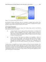
Because this DMRS design can be viewed as binding together the CS values of DMRS as well
as the channel impulse response (CIR) positions of different spatial layers with the maximum
distance constraint, as illustrated in Fig. 2 (Note that the relationship between α
i
and α
0
will
keep unchanged during CS hopping), we simply call it maximum distance binding (MDB).Its
benefits include:
• First, the distance between CIRs of different spatial layers in the time domain can be
always maximized, thus the interference between DMRS of different spatial layers can be
minimized;
• Second, no additional signaling is required for CS notification and hopping when support
uplink MIMO transmission, therefore, it is completely backwards compatible to LTE;
• Third, it can support time-domain inter-slot interpolation that is necessary for moderate to
high mobility cases.
419
Demodulation Reference Signal Design and Channel Estimation for LTE-Advanced Uplink
Fig. 2. CS extension with MDB
Actually, the same DMRS design principle can also be applied to the uplink multi-user MIMO
(MU-MIMO) transmission with single transmit antenna UEs. Now it only requires some
constraint in the uplink scheduling assignment for the CS values of multiple DMRS (because
n
(1)
DMRS
and n
PRS
are the same for all the UEs in the same cell, respectively) as follows
n
(2)
DMRS,i
=(n
(2)
DMRS,0
+
C
n
T
·i)mod(C), i = 0, 1, , n
T
−1(7)
where n
(2)
DMRS,0
is the scheduled value for the first UE.
In order to support the above CS scheduling constraint for MU-MIMO transmission, we have
two possible options:
• Option 1: No signaling modification
Because the current LTE specification only supports 8 possible values for n
(2)
DMRS
(3GPP,
TS 36.211), a limited number of combinations can be chosen in the uplink scheduling
with the MDB constraint (7) satisfied. Therefore, for the 2-user case, n
(2)
DMRS,i
∈
{(
0, 6), (2, 8), (3, 9), (4, 10)}; while for the 4-user case, n
(2)
DMRS,i
∈{(0, 3, 6, 9)}.
• Option 2: Slight signaling modification
If the specific field in downlink control information (DCI) format 0 for the CS of DMRS can
be increased from 3 bits to 4 bits, all the possible combinations in the CS scheduling for
MU-MIMO transmission can be supported with the MDB constraint (7) satisfied.
3.1.2 Further enhancement: CS + OCC
For high-order SU-MIMO, MU-MIMO and coordinated multi-point (CoMP) reception that
will be supported in the further evolvement of LTE, the number of superposed spatial layers
will increase to four or even eight. In order to reduce the interference between multiple spatial
layers, OCC, such as
[
+
1, +1
]
and
[
+
1, −1
]
, can be further introduced across the two DMRS
symbols within the same subframe.
For MU-MIMO and CoMP reception, CS + OCC can provide some special advantage
compared to CS only scheme, such as capability to multiplex UEs with different transmit
bandwidths and robustness to timing difference of multiple UEs. For SU-MIMO, CS + OCC
420
Advances in Vehicular Networking Technologies
may also be attractive for high-order MIMO transmission and/or high-order modulation. The
combination of CS and OCC could have two variations, i.e., CS + OCC with identical CS and
CS + OCC with offset CS (TI, 2009), as illustrated in Fig. 3 (a) and Fig. 3 (b), respectively, taking
four spatial layers for example.
(a) CS + OCC
(b) CS + OCC (offset)
Fig. 3. Combination of CS and OCC
However, OCC will lose its effectiveness in some cases, such as when the mobility
increases from low to moderate or PUSCH hopping happens within one subframe. In the
aforementioned situations, CS + OCC with identical CS, abbr. as CS + OCC, cannot work
at all; while CS + OCC with offset CS , abbr. as CS + OCC (offset), still can work, but in
essence only CS takes effect now. Obviously, CS + OCC (offset) occupies twice CS resources
compared to CS + OCC. Meanwhile, to introduce OCC into LTE-A uplink DMRS design, some
additional control signaling may be needed. Otherwise, the linkage between OCC and CS
must be defined to avoid increasing control signaling, i.e., the notification of OCC could be
realized in an explicit way.
3.2 Two-dimensional channel estimation
In order to obtain the time-frequency two-dimensional channel state information (CSI) in
the SC-FDMA uplink, two-dimensional channel estimation is needed for each subframe.
Without loss of generality, assume that the inter-symbol interference (ISI) and the inter-carrier
interference (ICI ) are small and neglectable. Therefore, for PDSCH and corresponding DMRS
421
Demodulation Reference Signal Design and Channel Estimation for LTE-Advanced Uplink
within one subframe, the received signal at the k-th subcarrier in the l-th SC-FDMA symbol
can be written as
Y
(k, l)=H(k, l) · X(k, l)+N(k, l) , k
0
≤ k < k
0
+ 12 · N
UL
RB
−1, 0 ≤ l < 14 (8)
where X
(k, l), H(k, l) and N(k, l) denote the transmitted signal, the channel frequency
response (CFR) and the additive white Gaussian noise (AWGN) with zero mean and variance
σ
2
for the k-th subcarrier in the l-th SC-FDMA symbol, respectively. k
0
is the frequency starting
position of PUSCH and N
UL
RB
is the uplink RB number for PUSCH. For the multipath wireless
channel within one SC-FDMA symbol, the CFR can be related to the CIR as
H
(k, l)=
G−1
∑
g=0
h(g, l) ·e
−j2πkg/K
(9)
where h
(g, l) is the g-th multipath component and G is the sample number corresponding to
the maximum multipath delay.
The first step of two-dimensional channel estimation is to obtain the initial estimated
superposed channels within the two DMRS symbols, i.e.,
ˆ
H
(k,3) and
ˆ
H(k,10), as follows
ˆ
H
(k, l)=Y(k, l) ·conj(r
(α
0
)
u,v
(k)), l = 3, 10 (10)
where co nj
(·) represents the complex conjugate and without loss of generality, PUSCH and
DMRS hopping are not considered.
To facilitate the following description, define the final estimated channel as
˜
H
(k, l). Then the
target of two-dimensional channel estimation is to derive each data symbol’s
˜
H
(k, l) from
ˆ
H
(k,3) and
ˆ
H(k,10). Taking the implementation complexity into account, two concatenated
one-dimensional channel estimation, i.e., frequency-dimensional channel estimation and
time-dimensional channel estimation, will be considered in this study.
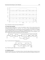
3.2.1 Frequency-dimensional channel estimation
For frequency-dimensional channel estimation, discrete-time Fourier transform (DFT) based
channel estimation (Edfors et al., 2000) could be utilized. However, because the RB allocation
to a given UE is generally only a small portion of the overall uplink bandwidth, the CIR energy
leakage will be observed in practice, as shown in Fig. 4, where the first and the second rows
are for two-antenna and four-antenna cases, while the left and the right columns are for RB#
= 1 and RB# = 10 cases, respectively. It’s obvious that the smaller the RB number, the more
severe the CIR energy leakage. This phenomenon will make the CIRs from different transmit
antennas superposed together and difficult to be separated with each other, especially when
the transmit antenna number becomes larger. Furthermore, the frequency domain Gibbs
phenomenon (Oppenheim et al., 1999) will appear at the edges of assigned consecutive RBs for
a given UE due to the signal discontinuities. Therefore, the estimation accuracy of traditional
DFT-based channel estimation will deteriorate significantly in practice.
In order to mitigate the aforementioned problems, an improved DFT-based channel estimation
was proposed for LTE(-A) uplink (Hou et al., 2009), which is illustrated in Fig. 5 for each
receive antenna of eNB. After serial-to-parallel (S/P) conversion and K-point fast Fourier
transform (FFT), the received signal is transformed into the frequency domain. Because each
UE (except for UEs in the same MU-MIMO transmission) occupies different RBs in the uplink,
we can first separate different UEs by way of frequency division multiplexing (FDM). Then
taking channel estimation for UE1 for example, multiply the separated received DMRS by
422
Advances in Vehicular Networking Technologies
Fig. 4. CIR energy leakage
the complex conjugate of the DMRS sequence assigned for the 1st spatial layer and perform
K-point inverse FFT (IFFT) to get the superposed CIRs in the time domain, i.e.,
ˆ
h
(g, l)=ifft(
ˆ
H
(k, l)),0 ≤ k < K, l = 3, 10 (11)
After the operation of dynamic CIR reservation (DCIR
2
), we can seperate the CIRs for different
spatial layers by way of different CS values. As for the operation of DCIR
2
, the dynamically
reserved CIR for each spatial layer consists of 2 parts with respect to the timing positions, i.e.,
(
C
n
T
·i) ·K, i = 0, 1, , n
T
−1:
•Rightpart
There are λ
·CP samples preserved with the following right boundary
(
C
n
T
·i) ·K + λ ·CP −1, i = 0, 1, , n
T
−1 (12)
where CP is the cyclic prefix length of the SC-FDMA symbol and λ is an adjustable
parameter (0
≤ λ < 1) that can be optimized in practical implementations.
•Leftpart
There are μ
·Δ samples preserved with the following left boundary
423
Demodulation Reference Signal Design and Channel Estimation for LTE-Advanced Uplink
[(
C
n
T
·i) ·K −μ · Δ + K]mod(K), i = 0, 1, , n
T
−1 (13)
where Δ is the main lobe width of CIR energy leakage (Δ
=
K
12·RB#
)andμ is an adjustable
parameter (0
≤ μ <
K/n
T
−CP
Δ
) that can be optimized in practical implementations. In
order to simply the adjustment, we can define
˜
Δ
=
K
12
and
˜
μ =
μ
RB#
, therefore,
˜
Δ becomes
a constant and only
˜
μ should be adjusted.
The proper choices of λ and
˜
μ are mainly determined by the noise level, the multipath delay
profile and the assigned RB number for a given UE. And afer DCIR
2
, we can obtain the CIR
for the i-th spatial layer as
˜
h
i
(g, l).
Finally, the frequency-dimensional channel estimation result of DMRS symbols for the i-th
spatial layer can be achieved by K-point FFT and provided to the following time-dimentional
channel estimation block.
˜
H
i
(k, l)=ifft(
˜
h
i
(g, l)),0 ≤ g < K, l = 3, 10 (14)
Another point should be emphasized is the operation of frequency domain
windowing/dewindowing . Due to the frequency domain Gibbs phenomenon caused
by the discontinuities at the edges of assigned consecutive RBs for a given UE, the overall
channel estimation accuracy will be degraded, especially at the edges of assigned consecutive
RBs. Therefore, some frequency domain window, such as Hanning window, Hamming
window, Blackman window, etc. (Oppenheim et al., 1999), can be further added (see the
dashed-line blocks in Fig. 5) to improve the channel estimation accuracy with some additional
complexity. For example, Blackman window will be adopted in our following computer
simulations.
w
(n)=0.42 −0.5cos (2πn/M)+0.08co s(4πn/M) (15)
where M is the window length and 0
≤ n ≤ M. In order not to eliminate the useful signals
within the assigned RBs, the window length should be larger than the assigned bandwidth
(12
· RB#) for the corresponding UE.
Note that the improved DFT-based channel estimation can be applied to not only LTE-A
MIMO uplink, but also LTE single-input single-output (SISO) or single-input multiple-output
(SIMO) uplink.
3.2.2 Time-dimensional channel estimation
After frequency-dimensional channel estimation, we only obtain channel estimation results
for two DMRS symbols within each subframe. In order to further acquire channel estimation
result for each data symbol, time-dimensional channel estimation is needed, i.e., inter-slot
interpolation via two DMRS symbols within each subframe. Two practical schemes are
time-dimensional linear interpolation (TD-LI) and time-dimensional average or despreading
(TD-Average/Despreading), i.e.,
˜
H
(k, l)=c
l
·
˜
H
(k,3)+(1 − c
l
) ·
˜
H
(k,10),0 ≤ l < 14 (16)
c
l
=(10 −l)/7 , TD − LI
c
l
= 1/2 , TD − Average
(17)
424
Advances in Vehicular Networking Technologies
Fig. 5. The improved DFT-based channel estimation
It should be noted that for the case of CS + OCC with identical CS, TD-Despreading must be
carried out before frequency-dimensional channel estimation.
4. Performance evaluation
Computer simulation results, including both block error rate (BLER) and throughput
performances, will be provided in this section to compare different DMRS design schemes,
i.e., CS only, CS + OCC and CS + OCC (offset).
The simulation parameters are listed in Table 1. Notice that the FFT size is larger than
the usable subcarrier number because of the existence of guard band. There are totally
50 RBs in the uplink and we consider two RB# allocation cases with RB#
= 4, 10,
respectively. Furthermore, 2 typical MIMO configurations, i.e., 2
× 2and4× 4, are both
simulated. The MIMO transmission scheme is spatial multiplexing without precoding and the
MIMO detection scheme is minimum mean square error (MMSE) detection. Without loss of
generality, synchronization error and PUSCH hopping are not considered. For the improved
DFT-based frequency-dimensional channel estimation, we simply chose λ
= 0.5 and
˜
μ = 0.2
and the frequency domain window length is set to be M
= 1.1 · RB# ·12. The channel model
is selected as typical urban (TU) with mobility of 3km/h or 30km/h.
First, BLER performances of different DMRS design schemes will be compared. The
same frequency-dimensional channel estimation is utilized for different DMRS design
schemes and time-dimensional channel estimation could be different, i.e., CS + OCC
can only use TD-Despreading, while CS only and CS + OCC (offset) can use TD-LI or
TD-Average/Despreading. Furthermore, the curve with perfect CSI is also provided in
each figure for comparison. The BLER performances are evaluated with two representative
configurations, i.e., 10RB with 16QAM and 4RB with 64QAM (the coding rate is 1/2), for
2
×2and4×4MIMO,respectively.
When the mobile speed is as low as 3km/h, Fig. 6 shows that for the 2
×2MIMOcasedifferent
DMRS design schemes have almost the same BLER performance. The only difference comes
from time-directional channel estimation, i.e., TD-Average/Despreading can achieve slightly
better performance than TD-LI due to the noise averaging effect in low mobility cases. And
from Fig. 7, it can be observed that for the 4
×4 MIMO case the introduction of OCC is helpful
to improve the BLER performance in low mobility cases, especially when the RB number is
small and/or the modulation order is high.
425
Demodulation Reference Signal Design and Channel Estimation for LTE-Advanced Uplink
Parameters Valu es
Carrier frequency 2GHz
Bandwidth 10MHz
FFT size 1024
Usable subcarrier # 600
Cyclic prefix 72
Assigned RB # 4, 10
MIMO configuration 2 ×2
(Spatial multiplexing)
4 ×4
MIMO detection MMSE
Modulation QPSK,16QAM,64QAM
Channel coding
Turbo
(Coding rate 1/2, 2/3, 3/4)
Synchronization Perfect
PUSCH hopping Disabled
DMRS design
CS Only
CS + OCC
CS + OCC (offset)
Frequency-dimensional Improved DFT-based
channel estimation
Time-dimensional TD-LI
channel estimation
TD-Average/TD-Despreading
Channel model Typical Urban (TU)
Mobile speed 3km/h, 30km/h
Table 1. Simulation parameters
However, if the mobile speed increases from low to moderate, i.e., from 3km/h to 30km/h, the
aforementioned conclusion has to be revised. As shown in Fig. 8, now CS only with TD-LI can
achieve the best performance and OCC will lose its effectiveness. The reason behind is that
when the mobile speed is as high as 30km/h, the wireless channels between two consecutive
slots are relatively fast time-varying, which makes TD-Average/Despreading cannot work
well. On the other hand, TD-LI can still track the time-varying channel effectively. Therefore,
from the mobility point of view, OCC has its apparent limitation, i.e., OCC will mainly work
in the low mobility cases. However, considering the major application scenario of MIMO is
the low mobility environment, OCC is still attractive for DMRS enhancement. And in the
following simulations only 3km/h is considered.
In order to provide a more comprehensive comparison between different DMRS design
schemes, the throughput performances with different modulation level and coding rate are
provided in Fig. 9 and Fig. 10 for 2
× 2and4× 4 MIMO, respectively. Three different
modulation schemes (QPSK, 16QAM, 64QAM) and three different coding rates (1/2, 2/3, 3/4)
are simulated, so in total there are nine combinations of modulation and coding. Considering
the mobile speed is low, TD-Average/Despreading will be adopted instead of TD-LI. Also
under this situation, because CS + OCC and CS + OCC (Offset) have neglectable performance
difference, only CS + OCC is simulated, together with CS only and perfect CSI. Therefore,
in each figure there are 27 curves, shown by different line styles and markers. For each
DMRS design scheme, only the envelop of nine curves (each with one specific combination
of modulation and coding) is highlighted to show the highest achievable throughput, which
426
Advances in Vehicular Networking Technologies
5 10 15 20 25
10
−3
10
−2
10
−1
10
0
E
s
/N
0
(dB)
BLER
Perfect CSI
CS Only−(TD−Average)
CS Only−(TD−LI)
CS+OCC
CS+OCC(oset)−(TD−Despreading)
CS+OCC(oset)−(TD−LI)
(a) 10RB, 16QAM
5 10 15 20 25
10
−3
10
−2
10
−1
10
0
E
s
/N
0
(dB)
BLER
Perfect CSI
CS Only−(TD−Average)
CS Only−(TD−LI)
CS+OCC
CS+OCC(oset)−(TD−Despreading)
CS+OCC(oset)−(TD−LI)
(b) 4RB, 64QAM
Fig. 6. BLER performance (2 ×2MIMO,TU,3km/h)
427
Demodulation Reference Signal Design and Channel Estimation for LTE-Advanced Uplink
5 10 15 20 25
10
−3
10
−2
10
−1
10
0
E
s
/N
0
(dB)
BLER
Perfect CSI
CS Only−(TD−Average)
CS Only−(TD−LI)
CS+OCC
CS+OCC(oset)−(TD−Despreading)
CS+OCC(oset)−(TD−LI)
(a) 10RB, 16QAM
15 20 25 30 35
10
−3
10
−2
10
−1
10
0
E
s
/N
0
(dB)
BLER
Perfect CSI
CS Only−(TD−Average)
CS Only−(TD−LI)
CS+OCC
CS+OCC(oset)−(TD−Despreading)
CS+OCC(oset)−(TD−LI)
(b) 4RB, 64QAM
Fig. 7. BLER performance (4 ×4MIMO,TU,3km/h)
428
Advances in Vehicular Networking Technologies
5 10 15 20 25
10
−3
10
−2
10
−1
10
0
E
s
/N
0
(dB)
BLER
Perfect CSI
CS Only−(TD−Average)
CS Only−(TD−LI)
CS+OCC
CS+OCC(oset)−(TD−Despreading)
CS+OCC(oset)−(TD−LI)
Fig. 8. BLER performance (4 ×4 MIMO, 10RB, 16QAM, TU, 30km/h)
429
Demodulation Reference Signal Design and Channel Estimation for LTE-Advanced Uplink
−5 0 5 10 15 20 25 30
0
1
2
3
4
5
E
s
/N
0
(dB)
Throughput(Mbps)
Perfect CSI
CS Only
CS+OCC
(a) 4RB
−5 0 5 10 15 20 25 30
0
2
4
6
8
10
12
14
E
s
/N
0
(dB)
Throughput(Mbps)
CS Only
CS+OCC
Perfect CSI
(b) 10RB
Fig. 9. Throughput performance (2 ×2MIMO,TU,3km/h)
430
Advances in Vehicular Networking Technologies
−5 0 5 10 15 20 25 30
0
1
2
3
4
5
6
7
8
9
10
E
s
/N
0
(dB)
Throughput(Mbps)
CS Only
Perfect CSI
CS+OCC
(a) 4RB
−5 0 5 10 15 20 25 30
0
5
10
15
20
25
E
s
/N
0
(dB)
Throughput(Mbps)
Perfect CSI
CS Only
CS+OCC
(b) 10RB
Fig. 10. Throughput performance (4 ×4MIMO,TU,3km/h)
431
Demodulation Reference Signal Design and Channel Estimation for LTE-Advanced Uplink
could be viewed as the throughput performance with the ideal adaptive modulation and
coding. From Fig. 9 and Fig. 10, we can observe that the introduction of OCC can improve
throughput to some extent when some of the following situations are satisfied, i.e., the antenna
number is large, the RB number is small, and the sigal-to-noise ratio is high.
5. Some basic conclusions and standardization progress
DMRS enhancement is a key step to support MIMO transmission, including SU-MIMO,
MU-MIMO and CoMP, for LTE-A uplink. In this study different DMRS design schemes as
well as channel estimation are investigated. In addition to the baseline of CS extension, the
further combination of CS with OCC is also discussed. In addition to the special advantage
for MU-MIMO and CoMP, CS + OCC is also attractive for high-order SU-MIMO to further
suppress the interferences among the increasing multiple spatial layers. With the enhanced
DMRS design and improved channel estimation, a higher spectrum efficiency can be realized
in LTE-A uplink. Meanwhile, considering the backwards compatibility, as less as possible
modification to the current LTE specification is preferred.
In the recent 3GPP RAN1 meetings, it was agreed that (3GPP, R1-102601)
• Introduce the OCC in Rel-10 without increasing uplink grant signaling overhead
• OCC can be used for both SU-MIMO and MU-MIMO
More design details about DMRS enhancement, such as CS and OCC linkage, DMRS hopping,
etc., are still under discussions and hopefully the uplink DMRS enhancement for LTE-A will
be finalized by the end of 2010.
6. References
3GPP. R1-102601: Final report of 3GPP TSG RAN WG1 #60bis, 3GPP TSG RAN WG1 Meeting
#61, Montreal, Canada, May 10-14, 2010.
3GPP TR 36.814 />3GPP TS 36.211 />Chu, D. C. (1972). Polyphase codes with good periodic correlation properties. IEEE Trans. Info.
Theory, Vol. 18, No. 4, July 1972, pp. 531-532, ISSN 0018-9448
Edfors, O.; Sandell, M.; van de Beek, J. J.; Wilson, S. K. & Borjesson, P. O. (2000). Analysis of
DFT-based channel estimators for OFDM. Wireless Pers. Commun., Vol. 12, No. 1, Jan.
2000, pp. 55-70, ISSN 0929-6212
Hou, X.; Zhang, Z. & Kayama, H. (2009). DMRS design and channel estimation for
LTE-Advanced MIMO uplink, Proc. IEEE VTC09-Fall, Alaska, USA, Sept. 20-23, 2009.
Oppenheim, A. V.; Schafer, R. W. & Buck, J. R. (1999). Discrete-Time Signal Pr ocessing, 2nd ed.,
Prentice Hall, ISBN 013216292X, New Jersey
Texas Instruments. R1-091843: Discussion on UL DM RS for SU-MIMO, 3GPP TSG RAN WG1
Meeting #57, San Francisco, USA, May 4-8, 2009.
432
Advances in Vehicular Networking Technologies