Advances in Vibration Analysis Research Part 3 docx
Bạn đang xem bản rút gọn của tài liệu. Xem và tải ngay bản đầy đủ của tài liệu tại đây (908.68 KB, 30 trang )
49
Free Vibration Analysis of Curved Sandwich Beams: A Dynamic Finite Element
largest difference being for the 5th frequency, where the FEM value is 1.94% smaller than
that of the DFE. When the number of elements used in the model is increased to 40, the
agreement between the two formulations becomes much better with the maximum relative
error being 0.46% for the 5th frequency. Increasing the number of elements from 20 to 40
considerably reduces the relative error between all the models; i.e., convergence. For the 1st
natural frequency, there is a perfect match between Ahmed’s results and the 20-element
DFE model. But with the increase in the mode number, the difference between the DFE and
Ahmed’s results grow to a maximum of 1.32% for the 5th natural frequency.
As seen in Table 3 above, increasing the number of elements in the DFE to 40 reduces the
values of all the DFE frequencies lower than those reported by Ahmed; the maximum
difference is now in the 1st mode, with the DFE frequency 0.32% smaller than the value
reported by Ahmed. Although increasing the number of elements seems to have gone in the
opposite direction of what it was intended, it should be noted that Ahmed (1971) only used
10 elements in the reported FEM results and based on the trend observed, increasing the
number of elements will lower the values of the frequencies, better matching the DFE results.
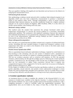
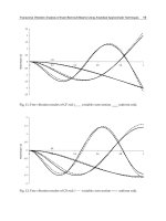
Using the 40-element DFE model, the mode shapes are calculated and illustrated in Figures
5 below. The mode shapes were found using values 99.99% of the actual natural frequencies
radial
radial
circumferential
circumferential
radial
radial
circumferential
circumferential
Fig. 5. First four normalized modes for clamped-clamped curved symmetric sandwich beam
of the system because displacements of the system become impossible to evaluate at the
values near the natural frequencies. As can be seen from Figures 5, the mode shapes for the
50
Advances in Vibration Analysis Research
curved symmetric sandwich beam with simply supported end conditions are dominated by
radial displacement which is the expected result due to the beam’s high axial stiffness in
comparison to its bending stiffness. It is worth noting that at the end points some axial
displacement is observed. This is in accordance with the fact that for the simply supported
end condition, the circumferential displacement is not forced to zero, giving the possibility
of a non-zero value for displacement at the end points.
5.4 Simply-Supported (S-S) straight symmetric sandwich beam
In the final numerical test, the curved symmetrical sandwich beam formulation is applied to
a straight beam case. The beam has a length of S = 0.9144 m, radius R = ∞, with face
thickness t = 0.4572 mm and core thickness tc = 12.7 mm. The mechanical properties of the
face layers are: E = 68.9 GPa and ρf = 2680 kg/m3, while the core has properties of Gc = 82.68
MPa and ρc = 32.8 kg/m3. The natural frequencies of the beam are calculated using the DFE
method as well as the 3-DOF and 4-DOF FEM formulations and compared to the data
published by Ahmed (1971) (see Table 4). In the case of a straight beam, the radial
displacement and circumferential displacements directly translate into the flexural and axial
displacements, respectively.
FEM
ωn
ω1
DFE
Ahmed,1971
3DOF
4DOF
20-Elem. 30-Elem. 40-Elem.
4DOF
20-Elem. 40-Elem. 20-Elem 40-Elem.
10-Elem
361.35
359.27
359.02
358.90
358.90
370.02
363.55
361.41
ω3
2938.6
2940.5
2924.3
2918.9
2918.9
ω5
6980.6
7044.7
ω7
11574.
11740.
ω9
16299.
16582.
16284.
3012.4
2958.6
2952.72
6966.0
6939.9
11559.
11498.
6939.8
7169.2
6993.5
6987.1
11498.
11885.
11667
11591.
16184.
16182.
16729.
16423.
16316.
Table 4. Natural frequencies (rad/s) of a simply-supported straight symmetric sandwich beam
6. Conclusion
Based on the theory developed by Ahmed (1971,1972) and the weak integral form of the
differential equations of motion, a dynamic finite element (DFE) formulation for the free
vibration analysis of symmetric curved sandwich beams has been developed. The DFE
formulation models the face layer as Euler-Bernoulli beams and allows the core to deform in
shear only. The DFE formulation is used to calculate the natural frequencies and mode
shapes for four separate test cases. In the first three cases the same curved beam, with
different end conditions, are used: cantilever, both ends clamped and lastly, both ends
simply supported. The final test case used the DFE formulation to determine the natural
frequencies of a simply supported straight sandwich beam.
All the numerical tests show satisfactory agreement between the results for the developed
DFE, FEM and those published in literature. For all test studies, when a similar number of
elements are used, the DFE matched more closely with the 3-DOF FEM formulation than
with Ahmed’s 4-DOF FEM results. The reason for this is that the DFE is derived from the 3-
51
Free Vibration Analysis of Curved Sandwich Beams: A Dynamic Finite Element
DOF FEM formulation and such a trend is expected. Ahmed (1971) goes on to explain that
the addition of an extra degree of freedom for each node has a tendency to lower the overall
stiffness of a sandwich beam element causing an overall reduction in values of the natural
frequencies. The mode shapes determined by the DFE formulation match the expectations
based on previous knowledge on the behaviour of straight sandwich beams. The results of
the DFE theory and methodology applied to the analysis of a curved symmetric sandwich
beam demonstrate that DFE can be successfully extended from a straight beam case to
produce a more general formulation. The proposed DFE is equally applicable to the
piecewise uniform (i.e., stepped) configurations and beam-structures. It is also possible to
further extend the DFE formulation to more complex configurations and to model geometric
non-uniformity and material changes over the length of the beam.
7. Acknowledgement
The support provided by Natural Science and Engineering Research Council of Canada
(NSERC), Ontario Graduate Scholarship (OGS) Program, and High Performance Computing
Virtual Laboratory (HPCVL)/Sun Microsystems is also gratefully acknowledged.
8. Appendix: development of DFE Stiffness matrices for curved symmetric
Euler-Bernoulli/Shear sandwich beam
The Dynamic Finite Element stiffness matrix for a symmetric curved sandwich beam is
developed from equations (12) and (13) found in Section 4. Applying the approximations for
the element variables, v(y) and w(y), and the test functions, δv(y) and δw(y), as shown in
expressions (19) and (20) to element integral equations (12) and (13) yield the element DFE
stiffness matrix defined in equation (21).
First, let us consider the element virtual work corresponding to the circumferential
displacement, v(y). Based on the governing differential equation (1), the critical value, or
changeover frequency, is then determined from
ω 2Q1 − 4 β 2 = 0
(A1)
For the frequencies below the changeover frequency, the element integral equation (12) can be
expressed as:
l
l
0
l
0
l
WVk = − ∫ (δ v "α 2 + δ vω 2Q1 )vdy + ∫ δ v(4 β 2 )vdy + [δ v 'α 2 v ]0 + ∫ (δ v 2 hβ 2 )w ' dy
(*)
(12 repeated)
0
k
[ k ]V
Uncoupled
[ kVW ]2×4 Coupling
where the first integral term, (*) vanishes due to the choice of the trigonometric basis
function for v(y), as stated in:
< P( y ) >V = cos(ε y ) sin(ε y )/ε ;
(16 repeated)
The next two terms, produce a symmetric 2x2 matrix [ k ]Vk that contains all the uncoupled
stiffness matrix elements associated with the displacement v(y). The inclusion of SCF term in
52
Advances in Vibration Analysis Research
(*) would make the solution to the corresponding characteristic equation (also used as basis
functions of approximation space) change form trigonometric to purely hyperbolic
functions. This, in turn, would lead to solution divergence of the DFE formulation, where
natural frequencies of the system cannot be reached using the determinant search method.
For the test cases examined here, the changeover frequency for the faces is well above the
range of frequencies being studied; therefore, the SCF term, representing the shear effect
from the core on the face layers, is kept out of the integral term (*) and evaluated as a part of
the second term, [ k ]Vk.
For the frequencies above the changeover frequency, the element integral equation can be rewritten as:
l
l
0
0
l
WVk = − ∫ (δ v "α 2 + δ v(ω 2Q1 − 4 β 2 )vdy + [δ v 'α 2 v ]0 + ∫ (δ v 2 hβ 2 )w ' dy
(*)
k
[ k ]V Uncoupled
(A2)
[ kVW ]2× 4 Coupling
where the SCF term is included in the integral term (*), which vanishes due to the choice of
purely trigonometric basis functions for v(y), similar to (16). The next term, then produces a
symmetric 2x2 matrix [ k ]Vk that contains all the uncoupled stiffness matrix elements
associated with the displacement v(y) and the final term, produces a 2x4 matrix [kVW] that
contain all the terms that couple the displacement v(y) with w(y).
⎡ kV (1,1) kV (1, 2) ⎤
k
[ k ]V = ⎢
⎥
⎣ sym. kV (2, 2)⎦
(A3)
⎡ kVW (1,1) kVW (1, 2) kVW (1, 3) kVW (1, 4) ⎤
[ kVW ]k = ⎢
⎥
⎣ kVW (2,1) kVW (2, 2) kVW (2, 3) kVW (2, 4)⎦
(A4)
Now considering equations (13):
l
k
WW = ∫ (δ w ""γ 2 − δ w " h 2 β 2 + δ w(α 2 / R 2 − ω 2Q1 ))wdy +
0
(**)
(13 repeated)
l
l
l
[δ w ' h 2 β 2 w ]l0 + [δ w "γ 2 w ']0 − [δ w "'γ 2 w ]0 + ∫ δ w '( 2 hβ 2 )vdy
0
k
[ k ]W Uncoupled
[ kWV ]4×2 Coupling
The first integral term, (**), in equation (13), vanishes due to the choice of mixed
trigonometric-hyperbolic basis functions for w(y), similar to (17):
< P( y ) > W = cos(σ y )
sin(σ y )
σ
cosh(τ y ) − cos(σ y ) sinh(τ y ) − sin(σ y )
σ 2 +τ 2
σ 3 +τ 3
,
(17 repeated)
The next three terms, produce a symmetric 4x4 matrix [k]Wk that contain all the uncoupled
stiffness matrix elements associated with the displacement w(y). The final term, produces a
4x2 matrix [kWV] that contain all the terms that couple the displacement w(y) with v(y). It is
important to note that [kWV] = [kVW]T.
Free Vibration Analysis of Curved Sandwich Beams: A Dynamic Finite Element
⎡ kW (1,1) kW (1, 2) kW (1, 3) kW (1, 4) ⎤
⎢
kW (2, 2) kW (2, 3) kW (2, 4)⎥
k
⎥
[ k ]W = ⎢
⎢
kW (3, 3) kW (3, 4) ⎥
⎢
⎥
kW (4, 4)⎥
⎢ sym.
⎣
⎦
⎡ kWV (1,1)
⎢ k (2,1)
WV
[ kWV ]k = ⎢
⎢ kWV (3,1)
⎢
⎢ kWV (4,1)
⎣
kWV (1, 2) ⎤
kWV (2, 2)⎥
⎥
kWV (3, 2) ⎥
⎥
kWV (4, 2)⎥
⎦
53
(A5)
(A6)
Matrices (A3), (A4), (A5) and (A6) are added according to equation (21) in order to obtain
the 6x6 element stiffness matrix for a symmetric straight sandwich beam.
⎡ kV (1,1) kVW (1,1) kVW (1, 2)
⎢
kW (1,1) kW (1, 2)
⎢
⎢
kW (2, 2)
[ k ]k = ⎢
⎢
⎢
⎢
⎢ sym.
⎣
kV (1, 2) kVW (1, 3) kVW (1, 4)⎤
kWV (1, 2) kW (1, 3) kW (1, 4) ⎥
⎥
kWV (2, 2) kW (2, 3) kW (2, 4) ⎥
⎥
kV (2, 2) kW (2, 3) kW (2, 4) ⎥
kW (3, 3) kW (3, 4) ⎥
⎥
kW (4, 4) ⎥
⎦
(A7)
9. References
Adique E. & Hashemi S.M. (2007). Free Vibration of Sandwich Beams using the Dynamic
Finite Element Method", in B.H.V. Topping, (Editor), "Proceedings of the Eleventh
International Conference on Civil, Structural and Environmental Engineering
Computing", Civil-Comp Press, Stirlingshire, UK, Paper 118, 2007.
doi:10.4203/ccp.86.118, St. Julians, Malta. 18-21 Sept 2007.
Adique E. & Hashemi S.M. (2008). Dynamic Finite Element Formulation and Free Vibration
Analysis of a Three-layered Sandwich Beam,” Proceedings of The 7th Joint CanadaJapan Workshop on Composite Materials, July 28-31, 2008, Fujisawa, Kanagawa,
Japan, pp. 93-100.
Adique E. & Hashemi S.M. (2009). A Super-Convergent Formulation for Dynamic
Analysis of Soft-Core Sandwich Beams", in B.H.V. Topping, L.F. Costa Neves,
R.C. Barros, (Editors), "Proceedings of the 12th International Conference on Civil,
Structural and Environmental Engineering Computing", Civil-Comp Press,
Stirlingshire, UK, Paper 98, 2009. doi:10.4203/ccp.91.98, Funchal, Madeira Island,
1-4 Sept. 2009.
Ahmed, K. M. (1971). Free vibration of curved sandwich beams by the method of finite
elements. Journal of Sound and Vibration, Vol. 18, No. 1, (September 1971) 61-74,
ISSN: 0022-460X.
54
Advances in Vibration Analysis Research
Ahmed, K. M. (1972). Dynamic analysis of sandwich beams. Journal of Sound and Vibration,
Vol. 21, No. 3, (April 1972) 263-276, ISSN: 0022-460X.
Baber, T.T.; Maddox, R.A. & Orozco, C.E. (1998). A finite element model for harmonically
excited viscoelastic sandwich beams. Computers &Structures, Vol. 66, No. 1, (January
1998) 105-113, ISSN: 0045-7949.
Banerjee, J. R. (1999). Explicit frequency equation and mode shapes of a cantilever beam
coupled in bending and torsion. Journal of Sound and Vibration, Vol. 224, No. 2, (July
1999) 267-281, ISSN: 0022-460X.
Banerjee, J. R. (2001). Explicit analytical expressions for frequency equation and mode
shapes of composite beams. International Journal of Solids and Structures, Vol. 38, No.
14 (April 2001) 2415-2426, ISSN: 0045-7949.
Banerjee, J. R. (2001). Frequency equation and mode shape formulae for composite
Timoshenko beams. Composite Structures, Vol. 51, No. 4, (May 2001) 381-388, ISSN:
0045-7949.
Banerjee, J. R. (2001). Dynamic stiffness formulation and free vibration analysis of
centrifugally stiffened Timoshenko beams. Journal of Sound and Vibration , Vol. 247,
No. 1, (October 2001) 97-115, ISSN: 0022-460X.
Banerjee, J. R. (2003). Free vibration of sandwich using the dynamic stiffness method.
Computers &Structures, Vol. 81, No. 18-19 (August 2003) 1915-1922, ISSN: 00457949.
Banerjee, J. R.; Cheung, C. W.; Morishima, R.; Perera, M. & Njuguna, J. (2007). Free vibration
of a three-layered sandwich beam using the dynamic stiffness method and
experiment. International Journal of Solids and Structures, Vol. 44, No. 22-23
(November 2007) 7543-7563, ISSN: 0045-7949.
Banerjee, J. R. and Sobey, A. J. (2005). Dynamic stiffness formulation and free vibration
analysis of a three-layered sandwich beam. International Journal of Solids and
Structures, Vol. 42, No. 8, (2005) 2181-2197, ISSN: 0045-7949.
Banerjee, J. R. And Su, H. (2004). Development of a dynamic stiffness matrix for free
vibration analysis of spinning beams. Computers &Structures, Vol. 82, No. 23-24
(September - October 2004) 2189-2197, ISSN: 0045-7949.
Banerjee, J. R. and Su, H. (2006). Dynamic stiffness formulation and free vibration analysis of
a spinning composite beam. Computers &Structures, Vol. 84, No. 19-20, (July 2006)
1208-1214, ISSN: 0045-7949.
Banerjee, J. R. & Williams, F.W. (1996). Exact dynamic stiffness matrix for composite
Timoshenko beams with applications. Journal of Sound and Vibration, Vol. 194, No. 4,
(July 1996), 573-585, ISSN: 0022-460X.
Banerjee, J. R. & Williams, F.W. (1995). Free vibration of composite beams – an exact method
using symbolic computation. Journal of Aircraft , Vol. 32, No. 3, (1995) 636-642, ISSN:
0021-8669.
Di Taranto, R. A. (1965). Theory of vibratory bending for elastic and viscoelastic layered
finite length beams. Journal of Applied Mechanics, Vol. 87, (1965) 881-886, ISSN: 00218936 (Print), eISSN: 1528-9036.
Fasana, A. & Marchesiello, S. (2001). Rayleigh-Ritz analysis of sandwich beams. Journal of
Sound and Vibration, Vol. 241, No. 4, 643-652, ISSN: 0022-460X.
Free Vibration Analysis of Curved Sandwich Beams: A Dynamic Finite Element
55
Hashemi, S. M. (1998). Free Vibration Analysis Of Rotating Beam-Like Structures: A Dynamic
Finite Element Approach. Ph.D. Dissertation, Department of Mechanical Engineering,
Laval University, Québec, Canada.
Hashemi, S. M. (2002). The use of frequency dependent trigonometric shape functions in
vibration analysis of beam structures – bridging the gap between FEM and exact
DSM formulations. Asian Journal of Civil Engineering, Vol. 3, No. 3&4, (2002) 33-56,
ISSN: 15630854.
Hashemi, S. M. & Adique, E.J. (2009). Free Vibration analysis of Sandwich Beams: A
Dynamic Finite Element, International Journal of Vehicle Structures & Systems
(IJVSS), Vol. 1, No 4, (November 2009) 59-65, ISSN: 0975-3060 (Print), 0975-3540
(Online).
Hashemi, S. M. & Adique, E.J (2010). A Quasi-Exact Dynamic Finite Element for Free
Vibration Analysis of Sandwich Beams, Applied Composite Materials, Vol. 17, No. 2,
(April 2010) 259-269, ISSN: 0929-189X (print version, 1573-4897 (electronic version),
doi:10.1007/s10443-009-9109-3.
Hashemi, S. M. & Borneman, S. R. (2004). Vibration analysis of composite wings
undergoing material and geometric couplings: a dynamic finite element
formulation. CD Proceedings of the 2004 ASME International Mechanical Engineering
Congress (IMECE 2004,) Aerospace Division, pp 1-7, November 2004, Anaheim, CA,
USA.
Hashemi, S. M. and Borneman, S. R. (2005). A dynamic finite element formulation for the
vibration analysis of laminated tapered composite beams. CD Proceedings of the
Sixth Canadian-International Composites Conference (CanCom), pp. 1-13, August 2005,
Vancouver, BC, Canada.
Hashemi, S. M.; Borneman, S. R. & Alighanbari, H. (2008). Vibration analysis of cracked
composite beams: a dynamic finite element. International Review of Aerospace
Engineering (I.RE.AS.E.), Vol. 1, No. 1, (February 2008) 110-121, ISSN: 1973-7459.
Hashemi, S. M.; Richard, M. J. & Dhatt, G. (1999). A new dynamic finite elements (DFE)
formulation for lateral free vibrations of Euler-Bernoulli spinning beams using
trigonometric shape functions. Journal of Sound and Vibration, Vol. 220, No. 4,
(March 1999) 601-624, ISSN: 0022-460X.
Hashemi, S. M. & Richard, M. J. (2000a). Free vibration analysis of axially loaded bendingtorsion coupled beams – a dynamic finite element (DFE). Computers and Structures ,
Vol. 77, No. 6, (August 2000) 711-724, ISSN: 0045-7949.
Hashemi, S. M. & Richard, M. J. (2000b). A dynamic finite element (DFE) for free vibrations
of bending-torsion coupled beams. Aerospace Science and Technology , Vol. 4, No. 1,
(January 2000) 41-55, ISSN: 1270-9638.
Hashemi, S. M. & Roach, A. (2008a). A dynamic finite element for coupled extensionaltorsional vibrations of uniform composite thin-walled beams. International Review of
Aerospace Engineering (I.RE.AS.E.) , Vol. 1, No. 2, (April 2008) 234-245, ISSN: 19737459.
Hashemi, S.M. & Roach, A. (2008b). Free vibration of helical springs using a dynamic finite
element mesh reduction technique. International Review of Mechanical Engineering,
Vol. 2, No. 3, (May 2008) 435-449 , ISSN: 1970 - 8734.
56
Advances in Vibration Analysis Research
Howson, W. P. & Zare, A. (2005). Exact dynamic stiffness matrix for flexural vibration of
three-layered sandwich beams. Journal of Sound and Vibration, Vol. 282, No. 3-5,
(April 2005) 753-767, ISSN: 0022-460X.
Mead, D. J. and Markus, S. (1968). The forced vibration of a three-layer, damped sandwich
beam with arbitrary boundary conditions. Journal of Sound and Vibration, Vol. 10,
No. 2, (September 1968) 163-175, ISSN: 0022-460X.
Sainsbury, M. G. & Zhang, Q. J. (1999). The Galerkin element method applied to the
vibration of damped sandwich beams. Computers and Structures , Vol. 71, No. 3,
(May 1999) 239-256, ISSN: 0045-7949.
Wittrick, W. H. & Williams, F. W. (1971). A general algorithm for computing natural
frequencies of elastic structures. Quarterly Journal of Mechanics and Applied
Mathematics, Vol. 24, No. 3, (August 1971) 263-284, Online ISSN 1464-3855 - Print
ISSN 0033-5614.
4
Some Complicating Effects in the
Vibration of Composite Beams
1Trakya
Metin Aydogdu1, Vedat Taskin1, Tolga Aksencer1,
Pınar Aydan Demirhan1 and Seckin Filiz2
University Department of Mechanical Engineering, Edirne,
2Trakya University Natural Sciences Institute, Edirne,
Turkey
1. Introduction
In the last 50-60 years, use of composite structures in engineering applications has increased.
Due to this fact many studies have been conducted related with composite structures (such
as: shells, plates and beams).
Bending, buckling and free vibration analysis of composite structures has taken
considerable attention. Beams are one of these structures that are used in mechanical, civil
and aeronautical engineering applications (such: robot arms, helicopter rotors and
mechanisms). Considering these applications free vibration problem of the composite beams
are studied in the previous studies. Kapania & Raciti, 1989 investigated the nonlinear
vibrations of un-symmetrically laminated composite beams. Chandashekhara et al., 1990
studied the free vibration of symmetric composite beams. Chandrashekhara & Bangera,
1993 investigated the free vibration of angle-ply composite beams by a higher-order shear
deformation theory. They used the shear flexible finite element method. Krishnaswamy et
al., 1992 solved the generally layered composite beam vibration problems. Chen et al., 2004
used the state-space based differential quadrature method to study the free vibration of
generally laminated composite beams. Solution methods for composite beam vibration
problems depend on the boundary conditions, some analytical (Chandrashekhara et al.,
1990, Abramovich, 1992, Krishnaswamy et al., 1992, Abramovic & Livshits, 1994, Khdeir &
Reddy, 1994, Eisenberger et al., 1995, Marur & Kant, 1996, Kant et al., 1998, Shi & Lam, 1999,
Yıldırım et al., 1999, Yıldırım, 2000, Matsunaga, 2001, Kameswara et al., 2001, Banerjee, 2001,
Chandrashekhara & Bangera, 1992, Ramtekkar et al., 2002, Murthy et al., 2005, Arya, 2003,
Karama et al., 1998, Aydogdu, 2005, 2006) solution procedures have been used.
Many factors can affect the vibrations of beams, in particular the attached springs and
masses, axial loads and dampers. This type of complicating effects is considered in the
vibration problem of isotropic beams. Gürgöze and his collogues studied vibration of
isotropic beam with attached mass, spring and dumpers (Gürgöze, 1986, Gürgöze, 1996,
Gürgöze & Erol, 2004). Vibration of Euler-Bernoulli beam carrying two particles and several
particles investigated by Naguleswaran, 2001, 2002. Nonlinear vibrations of beam-mass
system with different boundary conditions are investigated by Ozkaya & Pakdemirli, 1999,
Ozkaya et. al., 1997. They used multiscale perturbation technique in their solutions.
58
Advances in Vibration Analysis Research
It is interesting to note that, although mass or spring attached composite beams are used or
can be used in some engineering applications, their vibration problem is not generally
considered in the previous studies. Vibration of symmetrically laminated clamped-free
beam with a mass at the free end is studied by Chandrashekhara & Bangera, 1993.
The aim of present study is to fill this gap. Therefore in this study vibration of composite
beams with attached mass or springs is studied. After driving equations of motion different
boundary conditions, lamination angles, attached mass or spring are considered in detail.
2. Equation of motion
In this study, equations of motion of composite beams will be derived from Classical
Laminated Plate Theory (CLPT). For CLPT following displacement field is generally
assumed:
U( x , z ; t ) = u( x , t ) − zw, x
V ( x , z ; t ) = v( x , t ) − zw, y
(1)
W ( x , z ; t ) = w( x , t )
where U,V and W are displacement components of a point of the plate in the x, y and z
directions respectively and u, v and w are the displacement components of a point of the
beam in the midplane again in the x, y and z directions respectively. The comma after a
letter denotes partial derivative with respect to x and y. The Hooke’s law can be written in
the following form using CLPT:
⎤ ⎡
⎡
⎢ σ x ⎥ ⎢ Q11 Q12
⎢ σ ⎥ = ⎢Q
Q
22
⎢ y ⎥ ⎢ 21
⎢τ ⎥ ⎢Q
Q
62
⎣ 61
⎢ xy ⎥
⎦
⎣
⎤
⎡
Q ⎤⎢ ε ⎥
16 ⎥ x
⎢ε ⎥
Q ⎥
26 ⎥ ⎢ y ⎥
Q ⎥ ⎢γ ⎥
66 ⎦ ⎢ xy ⎥
⎦
⎣
(2)
where σx and σy are the in-plane normal stress components in the x and y directions
respectively, τxy is the shear stress in the x-y plane, εx, εy and γxy are normal strains and shear
strain respectively and Qij are the reduced transformed rigidities (Jones, 1975). These strains
are defined in the following form:
ε
x
=
∂U
∂V
, ε =
y ∂y
∂x
γ
xy
=
∂U ∂V
+
∂y ∂x
(3)
Applying Hamilton principle leads to the following equations of motion for laminated
composite plate.
N x , x + N xy , y = ρ u, tt
N xy , x + N y , y = ρ v, tt
Mx , xx + 2 Mxy , xy + M y , yy = ρ w, tt
where the force and moment resultants are defined in the following form.
(4)
59
Some Complicating Effects in the Vibration of Composite Beams
( N x , N y ,N xy ) =
h /2
∫ (σ x ,σ y ,τ xy )dz
−h / 2
(5)
( M x , M y ,M xy ) =
h /2
∫ (σ x ,σ y ,τ xy )zdz
−h / 2
(6)
These force and moment results can also be written in the following form:
⎡ N ⎤ ⎡A
⎢ x ⎥ ⎢ 11
⎢ N y ⎥ ⎢A
⎢ N ⎥ ⎢ 12
⎢ xy ⎥ ⎢ A16
⎢ M ⎥ = ⎢B
⎢ x ⎥ ⎢ 11
⎢ M y ⎥ ⎢ B12
⎢
⎥ ⎢
⎢ M xy ⎥ ⎣ B16
⎣
⎦
A
12
A
22
A
26
B
12
B
22
B
26
A
16
A
26
A
66
B
16
B
26
B
66
B
11
B
12
B
16
D
11
D
12
D
12
B
12
B
22
B
26
D
12
D
22
D
26
⎤
⎡ u
B ⎤⎢
,x ⎥
16 ⎥
⎢ v, y ⎥
B ⎥
26 ⎢
⎥
B ⎥ ⎢u , x + v , y ⎥
66 ⎥
⎥
D ⎥⎢ − w
, xx ⎥
16 ⎢
⎥⎢
⎥
D
26 ⎥ ⎢ − w, yy ⎥
D ⎥ ⎢ − 2w
⎥
66 ⎦
, xy ⎦
⎣
(7)
where extensional, coupling and bending rigidities are defined as follows:
h/2
(k )
∫ Qij dz
−h/2
h/2
Bij = ∫ Q ( k ) zdz
ij
−h/2
h/2
Dij = ∫ Q ( k ) z 2 dz
ij
−h/2
A =
ij
(8)
Now, consider a laminated composite beam with length L, width b and thickness h.
Equations of motion of laminated composite beams can be derived from Eq.(4) assuming
Ny=Nxy=My=Mxy=0.
N x , x = ρ u, tt
(9)
Mx , xx = ρ w, tt
Eq.(7) can be inverted in the following form:
⎡ *
⎡ u ⎤ ⎢ A11
,x⎥ ⎢
⎢
*
⎢ ε y ⎥ ⎢ A12
⎥ ⎢ *
⎢
⎢γ xy ⎥ ⎢ A16
⎢κ ⎥ = ⎢ *
⎢ x ⎥ ⎢ B11
⎢κ ⎥ ⎢ *
⎢ y ⎥ ⎢B
⎢κ xy ⎥ ⎢ 12
⎦ ⎢B*
⎣
⎣ 16
A*
12
A*
22
A*
26
B*
12
B*
22
B*
26
A*
16
A*
26
A*
66
B*
16
B*
26
B*
66
B*
11
B*
12
B*
16
D*
11
D*
12
D*
16
B*
12
B*
22
B*
26
D*
12
D*
22
D*
26
B* ⎤
16 ⎥
⎡N ⎤
B* ⎥⎢ x ⎥
26 ⎥ ⎢ 0 ⎥
⎥
B* ⎥⎢ 0 ⎥
66 ⎢
⎥
⎥
D * ⎥ ⎢M x ⎥
16 ⎢
⎥ 0 ⎥
⎥
D* ⎥⎢
26 ⎢ 0 ⎥
⎦
* ⎥⎣
D ⎥
66 ⎦
(10)
where Aij* ,Bij* ,Dij* are the members of inverse of rigidity matrix given in Eq.(7). Eq.(10) can
be written in the following form.
60
Advances in Vibration Analysis Research
= A* N + B * M
11 x
11 x
* N + D* M
w
=B
, xx
11 x
11 x
u
,x
(11)
Eq.(11) can be solved in term of Nx and Mx.
Mx =
*
* *
[( B11 )2 − ( A11D11 )]
*
*
B11u, x − B112 [
Nx =
*
B11
u, x +
*
A11
w, xx
*
* *
[( B11 )2 − ( A11D11 )]
*
B11
*
* *
[( B11 )2 − ( A11D11 )]
u, x +
* *
A11B11
(12)
*
A11
w, xx ]
*
* *
[( B11 )2 − ( A11D11 )]
(13)
Inserting equations (12)-(13) in equation (9) yields to:
A
∂ 2u
∂ 3w
∂ 2u
+B
=ρ
∂x 2
∂x 3
∂t 2
∂ 4w
∂ 3u
∂2w
D
+B
= −ρ
∂x 4
∂x 3
∂t 2
(14)
Where A, B and D are defined in the following form.
A=
*
( B11 )2
1
−
*
*
* *
A11 [( B11 )2 − ( A11D11 )]
B=−
D=
(15)
*
B11
(16)
*
A11
(17)
*
* *
[( B11 )2 − ( A11D11 )]
*
* *
[( B11 )2 − ( A11D11 )]
Eqs. (14) are the equations of motion of generally laminated composite beam for the
assumptions Ny=Nxy=My=Mxy=0. Boundary conditions of the generally laminated composite
beams can be written in the following form:
S : w = M x = N x = 0
C : w = w ,x = u = 0
(18)
F : M x = Q x = N x = 0
2.1 Symmetrically laminated composite beams
For symmetrically laminated composite beams coupling terms Bij ’s are zero. Then Eq. (14)
takes the following form.
61
Some Complicating Effects in the Vibration of Composite Beams
D
∂4w
∂2w
= −ρ
∂x 4
∂t 2
(19)
General solution of Eq.(19) can be written in the following form:
w( x ) = A sin(Ω x ) + B cos( Ω x ) + C sinh(Ω x ) + D cosh( Ω x )
Where A,B,C and D are undetermined coefficients, Ω 4 = ρω 2 L4 / E2 h 3
(20)
is non-dimensional
frequency parameter. Using boundary conditions given in Eq.(18) following Eigenvalue
determinants are obtained for different boundary conditions:
H-H boundary condition:
Following condition exists between undetermined coefficients given in Eq.(20): B=D=0
sin( Ω )
sinh(Ω )
=0
2 sin(Ω ) Ω 2 sinh(Ω )
−Ω
(21)
C-H boundary condition:
Following condition exists between undetermined coefficients given in Eq.(20): D=-B, C=-A:
sin( Ω ) − sinh(Ω )
cos( Ω ) − cosh( Ω )
=0
2 sin(Ω ) − Ω 2 sinh(Ω ) −Ω 2 cos(Ω ) − Ω 2 cosh(Ω )
−Ω
(22)
C-C boundary condition:
Following condition exists between undetermined coefficients given in Eq.(20): D=-B, C=-A:
sin(Ω ) − sinh(Ω )
cos(Ω ) − cosh(Ω )
=0
Ω cos(Ω ) − Ω cosh( Ω ) −Ω sin( Ω ) − Ω sinh(Ω )
(23)
C-F boundary condition:
Following condition exists between undetermined coefficients given in Eq.(20): D=-B, C=-A
−Ω 2 sin(Ω ) − Ω 2 sinh(Ω ) −Ω 2 cos(Ω ) − Ω 2 cosh(Ω )
=0
−Ω 3 cos(Ω ) − Ω 3 cosh(Ω ) −Ω 3 sin(Ω ) − Ω 3 sinh(Ω )
(24)
F-F boundary condition:
Following condition exists between undetermined coefficients given in Eq.(20): D=B, C=A:
−Ω 2 sin(Ω ) Ω 2 sinh(Ω )
=0
−Ω 2 cos(Ω ) Ω 2 cosh(Ω )
(25)
H-F boundary condition:
Following condition exists between undetermined coefficients given in Eq.(20): B=D=0:
−Ω 2 sin(Ω ) + Ω 2 sinh(Ω −Ω 2 cos(Ω ) + Ω 2 cosh(Ω )
=0
−Ω 3 cos(Ω ) + Ω 3 cosh( Ω ) Ω 3 sin( Ω ) + Ω 3 sinh(Ω )
(26)
62
Advances in Vibration Analysis Research
Solution of each determinant equation given in Eq.(21)-Eq.(26) gives frequency parameter of
symmetrically laminated composite beams.
2.2 Symmetrically laminated beams with attached mass or spring
Now consider a symmetrically laminated composite beam with attached mass or spring
(figure 1). Where η is length of first part of the beam. In order to investigate vibration of two
portion composite beam Eq.(20) is written for each portion in the following form:
w1 ( x ) = A1 sin(Ω x ) + B1 cos( Ω x ) + C1 sinh(Ω x ) + D1 cosh(Ω x )
w2 ( x ) = A2 sin(Ω x ) + B2 cos(Ω x ) + C 2 sinh( Ω x ) + D2 cosh(Ω x )
η
(27)
η
x
x
M
k
a)
b)
Fig. 1. Composite beam with attached mass (a) and spring (b).
Continuity conditions of the beam at x=η can be written in the following form:
w1 (η , t ) = w2 (η , t ),
'
w1 (η , t ) = w'2 (η , t )
''
w1 (η , t ) = w'' (η , t ),
2
(28)
'''
w1 (η , t ) − w''' (η , t ) + α mΩ 4 w1 (η , t ) = 0
2
3 w'''(η , t ) − Ω 3 w'''(η , t ) − α w (η , t ) = 0
Ω 1
s 1
2
(mass)
(spring)
Where dimensionless mass and spring parameter are defined in the following form:
αm =
M
ρ0L
, αs =
kL
AE
Using boundary conditions Eq.(18) and continuity conditions Eq.(28) following equations
are obtained for different boundary conditions and composite beams with attached mass
and spring at different position.
H-H boundary condition:
Following condition exists between undetermined coefficients given in Eq.(27): B1=D1=0:
0
0
S(ηΩ )
C (ηΩ )
0
S(Ω )
C (Ω )
Sh( Ω )
Ch( Ω )
0
−S( Ω ) −C ( Ω )
Sh( Ω )
Ch( Ω )
Sh(ηΩ ) −S(ηΩ ) −C (ηΩ ) −Sh(ηΩ ) −Ch(ηΩ )
=0
Ch(ηΩ ) −C (ηΩ ) −S(ηΩ ) −Ch(ηΩ ) −S(ηΩ )
−S(ηΩ ) Sh(ηΩ )
A61
A62
S(ηΩ )
A63
C (ηΩ )
A64
−Sh(ηΩ ) −Ch(ηΩ )
A65
A66
(29)
63
Some Complicating Effects in the Vibration of Composite Beams
With spring
A61 = −Ω 3C (ηΩ ) − α SS(ηΩ )
With mass
A61 = −C (ηΩ ) + α mΩ S(ηΩ )
A62 = Ω 3Ch(ηΩ ) − α SSh(ηΩ ) A62 = Ch(ηΩ ) + α mΩ Sh(ηΩ )
A63 = Ω 3C (ηΩ )
A63 = Ch(ηΩ )
A64 = −S(ηΩ )
A65 = −Ch(ηΩ )
A66 = −Sh(ηΩ )
3
A64 = −Ω S(ηΩ )
A65 = −Ω 3Ch(ηΩ )
A66 = −Ω 3Sh(ηΩ )
H-C boundary condition:
Following condition exists between undetermined coefficients given in Eq.(27): B1=D1=0:
0
0
S(ηΩ )
C (ηΩ )
0
S(Ω )
C (Ω )
Sh(Ω )
Ch(Ω )
0
−S(Ω )
C (Ω )
Ch(Ω )
Sh(Ω )
Sh(ηΩ ) −S(ηΩ ) −C (ηΩ ) −Sh(ηΩ ) −Ch(ηΩ )
=0
Ch(ηΩ ) −C (ηΩ ) −S(ηΩ ) −Ch(ηΩ ) −S(ηΩ )
−S(ηΩ ) Sh(ηΩ )
A61
A62
S(ηΩ )
A63
C (ηΩ )
A64
(30)
−Sh(ηΩ ) −Ch(ηΩ )
A65
A66
With mass
A61 = −C (ηΩ ) + α mΩ S(ηΩ )
A62 = Ch(ηΩ ) + α mΩ Sh(ηΩ )
A63 = C (ηΩ )
A65 = −Ch(ηΩ )
A64 = −S(ηΩ )
A66 = −Sh(ηΩ )
With spring
A61 = −Ω 3C (ηΩ ) − α SS(ηΩ )
A62 = Ω 3Ch(ηΩ ) − α SSh(ηΩ )
A63 = Ω 3C (ηΩ )
A64 = −Ω 3S(ηΩ )
A65 = −Ω 3Ch(ηΩ )
A66 = −Ω 3Sh(ηΩ )
C-C boundary condition:
Following condition exists between undetermined coefficients given in Eq.(27): D1=-B1,
C1=-A1:
0
0
0
0
S(ηΩ ) − Sh(ηΩ )
C (ηΩ ) − Ch(ηΩ )
C (ηΩ ) − Ch(ηΩ )
−S(ηΩ ) − Sh(ηΩ )
−S(ηΩ ) − Sh(ηΩ ) −C (ηΩ ) − Ch(ηΩ )
A61
A62
S(Ω )
C(Ω )
C (Ω )
−S(Ω )
Sh( Ω )
Ch(Ω )
Ch( Ω )
Sh(Ω )
−S(ηΩ ) −C (ηΩ ) −Sh(ηΩ ) −Ch(ηΩ )
=0
−C (ηΩ ) −S(ηΩ ) −Ch(ηΩ ) −S(ηΩ )
S(ηΩ )
A63
C (ηΩ )
A64
−Sh(ηΩ ) −Ch(ηΩ )
A65
A66
(31)
64
Advances in Vibration Analysis Research
With mass
A61 = −C (ηΩ ) − Ch(ηΩ ) + α mΩ S(ηΩ ) − α mΩ Sh(ηΩ )
A62 = S(ηΩ ) − Sh(ηΩ ) + α mΩ C (ηΩ ) − α mΩ Ch(ηΩ )
A63 = C (ηΩ )
A65 = −Ch(ηΩ )
A64 = −S(ηΩ )
A66 = −Sh(ηΩ )
With spring
A61 = −Ω 3C (ηΩ ) − Ω 3Ch(ηΩ ) − α sS(ηΩ ) + α sSh(ηΩ )
A62 = Ω 3S(ηΩ ) − Ω 3Sh(ηΩ ) − α sC (ηΩ ) + α sCh(ηΩ )
A63 = Ω 3C (ηΩ )
A64 = −Ω 3S(ηΩ )
A65 = −Ω 3Ch(ηΩ )
A66 = −Ω 3Sh(ηΩ )
C-F boundary condition:
Following condition exists between undetermined coefficients given in Eq.(27): D1=-B1,
C1=-A1:
0
0
S(ηΩ ) − Sh(ηΩ )
C (ηΩ ) − Ch(ηΩ )
0
0
C (ηΩ ) − Ch(ηΩ )
−S(ηΩ ) − Sh(ηΩ )
−S(ηΩ ) − Sh(ηΩ ) −C (ηΩ ) − Ch(ηΩ )
A61
A62
−S(Ω ) −C (Ω )
Sh(Ω ))
Ch( Ω )
−C (Ω )
S( Ω )
Ch(Ω )
Sh(Ω )
−S(ηΩ ) −C (ηΩ ) −Sh(ηΩ ) −Ch(ηΩ )
=0
−C (ηΩ ) −S(ηΩ ) −Ch(ηΩ ) −S(ηΩ )
S(ηΩ )
A63
C (ηΩ )
A64
(32)
−Sh(ηΩ ) −Ch(ηΩ )
A65
A66
With spring
With mass
3
3
A61 = −C (ηΩ ) − Ch(ηΩ ) + α mΩ S(ηΩ ) − α mΩ Sh(ηΩ ) A61 = −Ω C (ηΩ ) − Ω Ch(ηΩ ) − α sS(ηΩ ) + α sSh(ηΩ )
A62 = S(ηΩ ) − Sh(ηΩ ) + α mΩ C (ηΩ ) − α mΩ Ch(ηΩ )
A63 = C (ηΩ )
A64 = −S(ηΩ )
A65 = −Ch(ηΩ )
A66 = −Sh(ηΩ )
A62 = Ω 3S(ηΩ ) − Ω 3Sh(ηΩ ) − α sC (ηΩ ) + α sCh(ηΩ )
A63 = Ω 3C (ηΩ )
A64 = −Ω 3S(ηΩ )
A65 = −Ω 3Ch(ηΩ )
A66 = −Ω 3Sh(ηΩ )
F-F boundary condition
Following condition exists between undetermined coefficients given in Eq.(27): D1=B1,
C1=A1:
0
0
S(ηΩ ) + Sh(ηΩ )
C (ηΩ ) + Ch(ηΩ )
0
0
C (ηΩ ) + Ch(ηΩ )
−S(ηΩ ) + Sh(ηΩ )
−S(ηΩ ) + Sh(ηΩ ) −C (ηΩ ) + Ch(ηΩ )
A61
A62
−S( Ω ) −C ( Ω ) Sh( Ω ))
Ch( Ω )
−C ( Ω )
S( Ω )
Ch( Ω )
Sh( Ω )
−S(ηΩ ) −C (ηΩ ) −Sh(ηΩ ) −Ch(ηΩ )
=0
−C (ηΩ ) S(ηΩ ) −Ch(ηΩ ) −Sh(ηΩ )
S(ηΩ )
A63
C (ηΩ )
A64
−Sh(ηΩ ) −Ch(ηΩ )
A65
A66
(33)
65
Some Complicating Effects in the Vibration of Composite Beams
With mass
A61 = −C (ηΩ ) − Ch(ηΩ ) + α mΩ S(ηΩ ) + α mΩ Sh(ηΩ )
A62 = S(ηΩ ) − Sh(ηΩ ) + α mΩ C (ηΩ ) + α mΩ Ch(ηΩ )
A63 = C (ηΩ )
A65 = −Ch(ηΩ )
A64 = −S(ηΩ )
A66 = −Sh(ηΩ )
With spring
A61 = −Ω 3C (ηΩ ) + Ω 3Ch(ηΩ ) − α sS(ηΩ ) − α sSh(ηΩ )
A62 = Ω 3S(ηΩ ) + Ω 3Sh(ηΩ ) − α sC (ηΩ ) + α sCh(ηΩ )
A63 = Ω 3C (ηΩ )
A64 = −Ω 3S(ηΩ )
A65 = −Ω 3Ch(ηΩ )
A66 = −Ω 3Sh(ηΩ )
H-F boundary condition:
Following condition exists between undetermined coefficients given in Eq.(27): B1=D1=0:
0
0
S(ηΩ )
C (ηΩ )
0
−S(Ω ) −C (Ω )
Sh(Ω ))
Ch(Ω )
0
−C (Ω )
S(Ω )
Ch(Ω )
Sh(Ω )
Sh(ηΩ ) −S(ηΩ ) −C(ηΩ ) −Sh(ηΩ ) −Ch(ηΩ )
=0
Ch(ηΩ ) −C(ηΩ ) S(ηΩ ) −Ch(ηΩ ) −Sh(ηΩ )
−S(ηΩ ) Sh(ηΩ )
A61
A62
S(ηΩ )
C(ηΩ )
A63
A64
With mass
(34)
−Sh(ηΩ ) −Ch(ηΩ )
A65
A66
With spring
A61 = −C (ηΩ ) + α mΩ S(ηΩ )
A61 = −Ω 3C (ηΩ ) − α sS(ηΩ )
A63 = C (ηΩ )
A64 = −S(ηΩ )
A65 = −Ch(ηΩ )
A63 = Ω 3C (ηΩ )
A62 = Ch(ηΩ ) + α mΩ Sh(ηΩ )
A66 = −Sh(ηΩ )
A62 = Ω 3Ch(ηΩ ) − α sSh(ηΩ )
A64 = −Ω 3S(ηΩ )
A65 = −Ω 3Ch(ηΩ )
A66 = −Ω 3Sh(ηΩ )
Solution of each determinant equation given in Eq.(29)-Eq.(34) gives frequency parameter of
symmetrically laminated beams with attached point mass or spring at the different location
of the beam.
3. Numerical results
In this section, firstly, numerical results are given for vibration of composite beams with or
without attached mass or springs. In order to check validity of present results first five
flexural vibration frequencies of laminated composite beams are compared with previous
results (Reddy, 1997) and good agreement is observed between two results. After checking
66
Advances in Vibration Analysis Research
validity of present formulation, vibration of composite beams with attached mass or spring
is investigated for different boundary conditions. Material properties are chosen as: E1=25E2,
G12=0.5E2 and ν12=0.3. Obtained parametrical results are given in figures. In order to
completeness of present study, first five frequency of symmetric three layer (θ/-θ/θ)
composite beams are given in Fig.2. According to Fig. 2, dimensionless frequency
parameters decrease with increasing lamination angle θ. This is due to decrease in rigidities
Dij with increasing θ. The frequency gap is narrowing for higher θ, so this type of beams
should be carefully designed. Highest frequencies are obtained for C-C and F-F boundary
conditions where as lowest one is obtained for C-F boundary condition.
Variation of frequency ratio of composite beams with attached mass to composite beam
without mass (Ωm/Ω0) is depicted in Fig.3 for different boundary conditions. According to
this figure, ratio of frequencies is insensitive to lamination angle θ. The lowest frequencies
generally are most affected by attached mass. Influence of attached mass is decreasing with
increasing mode number. This fact can be explained by considering mode shapes of
vibrating composite beams. For H-H, C-C, H-C and F-F beams η=0.25 is a nodal point for
fourth frequency, therefore this frequency is not affected by attached mass as expected.
Highest %40 and lowest %20 changes are observed for frequencies for different boundary
conditions.
400
Mode 1
Mode 2
Mode 3
Mode 4
Mode 5
200
Mode 1
Mode 2
Mode 3
Mode 4
Mode 5
300
Ω0
300
Ω0
H-F
400
C-C
100
200
100
0
0
0
15
30
45
60
75
90
0
15
30
[θ /−θ/ θ]
400
60
75
90
H-H
400
H-C
Mode 1
Mode 2
Mode 3
Mode 4
Mode 5
200
Mode 1
Mode 2
Mode 3
Mode 4
Mode 5
300
Ω0
300
Ω0
45
[θ /−θ/ θ]
200
100
100
0
0
0
15
30
45
[θ /−θ/ θ]
60
75
90
0
15
30
45
60
75
[θ /−θ/ θ]
Fig. 2. Variation of frequency parameter of composite beam with lamination angle θ.
90
67
Some Complicating Effects in the Vibration of Composite Beams
1,4
1,4
H-H
1,2
Ωm/Ω0
Ωm/Ω0
1,2
1,0
1,0
0,8
0,8
0,6
0,6
0
15
30
45
60
75
0
90
15
30
1,4
60
75
90
1,4
F-F
Mode 1
Mode 2
Mode 3
Mode 4
Mode 5
H-F
1,0
Mode 1
Mode 2
Mode 3
Mode 4
Mode 5
1,2
Ωm/Ω0
1,2
Ωm/Ω0
45
[ θ / −θ / θ ]
[ θ / −θ / θ ]
0,8
1,0
0,8
0,6
0,6
0
15
30
45
60
75
90
0
15
30
[ θ / −θ / θ ]
45
60
75
90
[ θ / −θ / θ ]
1,4
1,4
C-F
C-C
Mode 1
Mode 2
Mode 3
Mode 4
Mode 5
1,0
0,8
Mode 1
Mode 2
Mode 3
Mode 4
Mode 5
1,2
Ωm/Ω0
1,2
Ωm/Ω0
Mode 1
Mode 2
Mode 3
Mode 4
Mode 5
H-C
Mode 1
Mode 2
Mode 3
Mode 4
Mode 5
1,0
0,8
0,6
0,6
0
15
30
45
[ θ / −θ / θ ]
60
75
90
0
20
40
60
80
[ θ / −θ / θ ]
Fig. 3. Variation of frequency ratio of composite beam with lamination angle for αm=1 and
η=0,25 .
Variation of frequency ratio of composite beams with attached spring to composite beam
without spring (Ωs/Ω0) is given in Fig.4 for different boundary conditions. According to this
figure, ratio of frequencies is insensitive to lamination angle θ. Effect of attached spring on
the frequency ratio is negligible for composite beams with at least one clamped edge. The
beams with F-F and H-F boundary conditions are most affected by attached mass. For these
boundary conditions spring behaves like a hinged boundary condition and decreases
frequency of composite beam.
68
Advances in Vibration Analysis Research
1,6
1,6
C-C
Mode 1
Mode 2
Mode 3
Mode 4
Mode 5
1,4
1,0
0,8
1,0
0,8
0,6
0,6
0,4
0,4
0
20
40
60
80
0
15
30
[ θ / −θ / θ ]
60
75
90
1,6
F-F
Mode 1
Mode 2
Mode 3
Mode 4
Mode 5
1,4
1,2
1,0
0,8
H-F
1,4
Mode 1
Mode 2
Mode 3
Mode 4
Mode 5
1,2
Ωs/Ω0
Ωs/Ω0
45
[ θ / −θ / θ ]
1,6
1,0
0,8
0,6
0,6
0,4
0,4
0
15
30
45
60
75
90
0
15
30
[ θ / −θ / θ ]
45
60
75
90
[ θ / −θ / θ ]
1,6
1,6
Mode 1
Mode 2
Mode 3
Mode 4
Mode 5
H-C
1,4
1,0
0,8
H-H
1,4
1,2
Ωs/Ω0
1,2
Ωs/Ω0
Mode 1
Mode 2
Mode 3
Mode 4
Mode 5
1,2
Ωs/Ω0
Ωs/Ω0
1,2
C-F
1,4
1,0
Mode 1
Mode 2
Mode 3
Mode 4
Mode 5
0,8
0,6
0,6
0,4
0,4
0
15
30
45
[ θ / −θ / θ ]
60
75
90
0
15
30
45
60
75
90
[ θ / −θ / θ ]
Fig. 4. Variation of frequency ratio of symmetric angle-ply composite beam with lamination
angle for αs=10 and η=0,25.
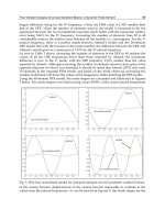
In Fig. 5, variation of frequency ratio with αm is given for three layer symmetric angle-ply
(300/-300/300) composite beams. Increasing αm decreases frequency of the composite beam.
Different decreases are observed for different boundary conditions.
69
Some Complicating Effects in the Vibration of Composite Beams
C-C
Mode 1
Mode 2
Mode 3
Mode 4
Mode 5
Ωm/Ω0
1,2
C-F
1,4
1,0
1,0
0,8
0,8
0,6
0,6
0,00
0,25
0,50
0,75
0,00
1,00
0,25
F-F
1,4
Mode 1
Mode 2
Mode 3
Mode 4
Mode 5
1,4
H-F
1,2
Ωm/Ω0
1,2
Ωm/Ω0
0,50
0,75
1,00
αm
αm
1,0
Mode 1
Mode 2
Mode 3
Mode 4
Mode 5
1,0
0,8
0,8
0,6
0,6
0,00
0,25
0,50
0,75
1,00
0,00
0,25
αm
H-C
1,2
0,50
0,75
1,00
αm
H-H
1,4
Mode 1
Mode 2
Mode 3
Mode 4
Mode 5
Mode 1
Mode 2
Mode 3
Mode 4
Mode 5
1,2
Ωm/Ω0
1,4
Ωm/Ω0
Mode 1
Mode 2
Mode 3
Mode 4
Mode 5
1,2
Ωm/Ω0
1,4
1,0
1,0
0,8
0,8
0,6
0,6
0,00
0,25
0,50
αm
0,75
1,00
0,00
0,25
0,50
0,75
1,00
αm
Fig. 5. Variation of frequency ratio of symmetric angle-ply composite beam (300/-300/300)
with αm for η=0,25.
Variation of frequency ratio with αs is given in Fig. 6 for three layer symmetric angle-ply
(300/-300/300) composite beams. Increasing αs decreases frequency of the composite beam
for F-F and H-F boundary conditions. For these two boundary conditions zero frequencies
exist for rigid body motions. Attaching a spring prevents from rigid body motion and these
70
Advances in Vibration Analysis Research
zero frequencies turn two none zero frequencies. Other boundary conditions are insensitive
to increase of αs for given range.
1,4
1,4
H-H
0,8
Ωm/Ω 0
1,0
0,8
H-C
1,2
1,0
Ωm/Ω0
1,2
0,6
0,4
0,4
Mode 1
Mode 2
Mode 3
Mode 4
Mode 5
0,2
0,0
0,6
Mode 1
Mode 2
Mode 3
Mode 4
Mode 5
0,2
0,0
-0,2
-0,2
0,00
0,25
0,50
0,75
0,00
1,00
0,25
H-F
1,2
Ωm/Ω0
1,0
0,8
1,4
Mode 1
Mode 2
Mode 3
Mode 4
Mode 5
F-F
1,00
Mode 1
Mode 2
Mode 3
Mode 4
Mode 5
1,0
0,6
0,4
0,8
0,6
0,4
0,2
0,2
0,0
0,0
-0,2
-0,2
0,00
0,25
0,50
0,75
0,00
1,00
0,25
0,50
0,75
1,00
αs
αs
1,50
1,4
C-F
1,0
C-C
1,25
1,00
0,8
0,6
Mode 1
Mode 2
Mode 3
Mode 4
Mode 5
0,4
0,2
0,0
Ω m /Ω 0
1,2
Ω m/Ω0
0,75
1,2
Ωm/Ω0
1,4
0,50
αs
αs
0,75
0,50
Mode 1
Mode 2
Mode 3
Mode 4
Mode 5
0,25
0,00
-0,2
0,00
0,25
0,50
αs
0,75
1,00
0,00
0,25
0,50
0,75
1,00
αs
Fig. 6. Variation of frequency ratio of symmetric angle-ply composite beam (300/-300/300)
with αs for η=0,25.
In Fig. 7, variation of frequency ratio of composite beam with η for αm=1 and η=0.25 are
given for three layer symmetric angle-ply (300/-300/300) composite beams. Generally, lower
71
Some Complicating Effects in the Vibration of Composite Beams
frequencies are most affected by position of attached mass. Forth frequency is not affected
by position of attached mass for boundary conditions other than F-F and F-H. This is due to
nodal points coincides with position of attached masses.
Mode 1
Mode 2
Mode 3
Mode 4
Mode 5
C-F
1,4
Mode 1
Mode 2
Mode 3
Mode 4
Mode 5
0,50
0,75
1,2
Ω m /Ω 0
Ω m /Ω 0
C-C
1,0
0,8
0,6
0,4
0,25
0,50
0,75
0,25
η
η
F-F
1,4
1,4
1,2
1,0
1,0
Ω m /Ω 0
Ω m /Ω 0
1,2
H-F
0,8
Mode 1
Mode 2
Mode 3
Mode 4
Mode 5
0,6
0,4
0,25
0,50
0,8
Mode 1
Mode 2
Mode 3
Mode 4
Mode 5
0,6
0,4
0,75
0,25
αm
1,4
H-C
0,75
η
Mode 1
Mode 2
Mode 3
Mode 4
Mode 5
1,0
1,4
0,8
H-H
1,2
Ω m /Ω 0
Ω m /Ω 0
1,2
0,50
Mode 1
Mode 2
Mode 3
Mode 4
Mode 5
1,0
0,8
0,6
0,6
0,4
0,4
0,25
0,50
η
0,75
0,25
0,50
0,75
η
Fig. 7. Variation of frequency ratio of symmetric angle-ply composite beam (300/-300/300)
with η for αm=1and η=0,25.
72
Advances in Vibration Analysis Research
1,50
1,50
H-H
1,25
1,00
0,75
0,50
Mode 1
Mode 2
Mode 3
Mode 4
Mode 5
0,25
0,00
0,25
0,50
Ω m /Ω 0
1,00
Ω m /Ω 0
H-C
1,25
0,75
0,50
Mode 1
Mode 2
Mode 3
Mode 4
Mode 5
0,25
0,00
0,75
0,25
η
1,50
H-F
1,25
F-F
Mode 1
Mode 2
Mode 3
Mode 4
Mode 5
0,75
0,50
Mode 1
Mode 2
Mode 3
Mode 4
Mode 5
0,50
0,75
1,25
1,00
Ω m /Ω 0
1,00
Ω m /Ω 0
0,75
η
1,50
0,25
0,75
0,50
0,25
0,00
0,00
0,25
0,50
0,75
0,25
η
η
1,50
1,50
C-C
C-F
1,25
1,25
1,00
0,75
0,50
Mode 1
Mode 2
Mode 3
Mode 4
Mode 5
0,25
0,00
0,25
0,50
η
0,75
Ω m /Ω 0
1,00
Ω m /Ω 0
0,50
0,75
0,50
Mode 1
Mode 2
Mode 3
Mode 4
Mode 5
0,25
0,00
0,25
0,50
0,75
η
Fig. 8. Variation of frequency ratio of symmetric angle-ply composite beam (300/-300/300)
with η for αs=1 and η=0,25.
Variation of frequency ratio of composite beam with η for αs=1 and η=0.25 are given in Fig.
8 for three layer symmetric angle-ply (300/-300/300) composite beams. Similar to Fig. 7
generally lower frequencies are most affected by position of attached spring. Forth
frequency is not affected by position of attached spring for boundary conditions other than
F-F and F-H. This is due to nodal points coincides with position of attached spring.
73
Some Complicating Effects in the Vibration of Composite Beams
In Fig. 9-10, variation of frequency parameter of composite beam with lamination angle for
αs=1, αm=1 and η=0.25 for different number of layers (single, three and four layer) are given
respectively. First frequencies are insensitive to number of layers but for the fourth
frequencies higher frequencies are obtained with increasing number of layers.
C-C
400
Mode 1
Mode 1
Mode 1
Mode 5
Mode 5
Mode 5
200
200
0
0
0
20
40
60
80
0
15
30
[ θ / −θ / θ ]
400
45
60
75
90
[ θ / −θ / θ ]
F-F
Mode 1
Mode 1
Mode 1
Mode 5
Mode 5
Mode 5
300
400
1 layer
3 layer
4 layer
1 layer
3 layer
4 layer
200
Mode 1
Mode 1
Mode 1
Mode 5
Mode 5
Mode 5
H-F
300
Ω
Ω
1 layer
3 layer
4 layer
1 layer
3 layer
4 layer
100
100
100
1 layer
3 layer
4 layer
1 layer
3 layer
4 layer
200
100
0
0
0
15
30
45
60
75
90
0
15
30
[ θ / −θ / θ ]
400
H-C
300
45
60
75
90
[ θ / −θ / θ ]
Mode 1
Mode 1
Mode 1
Mode 5
Mode 5
Mode 5
400
1 layer
3 layer
4 layer
1 layer
3 layer
4 layer
200
Mode 1
Mode 1
Mode 1
Mode 5
Mode 5
Mode 5
H-H
300
Ω
Ω
Mode 1
Mode 1
Mode 1
Mode 5
Mode 5
Mode 5
C- F
300
Ω
Ω
300
400
1 layer
3 layer
4 layer
1 layer
3 layer
4 layer
1 layer
3 layer
4 layer
1 layer
3 layer
4 layer
200
100
100
0
0
0
15
30
45
[ θ / −θ / θ ]
60
75
90
0
15
30
45
60
75
[ θ / −θ / θ ]
Fig. 9. Variation of frequency parameter of symmetric angle-ply composite beam with
lamination angle for αs=1 and η=0,25 for different number of layers.
90