Advances in Vibration Analysis Research Part 9 pptx
Bạn đang xem bản rút gọn của tài liệu. Xem và tải ngay bản đầy đủ của tài liệu tại đây (790.93 KB, 30 trang )
1 3 5 7 9 11 13 15 17 19 21 23 25 27
2.0−
0
0.2
0.4
0.6
0.8
1
experimental
FE
−1
5.0−
0
0.5
1
mode 1
1 3 5 7 9 11 13 15 17 19 21 23 25 27
−1
5.0−
0
0.5
1
mode 3
−1
5.0−
0
0.5
1
mode 4
1 3 5 7 9 11 13 15 17 19 21 23 25 27
−1
5.0−
0
0.5
1
mode 5
mode 2
sensor n°
sensor n°
1 3 5 7 9 11 13 15 17 19 21 23 25 27
sensor n°
1 3 5 7 9 11 13 15 17 19 21 23 25 27
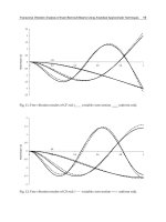
Fig. 13. Comparison between numerical and experimental transverse components of the
mode shapes of the Vallone Scarpa Bridge.
6. References
Bendat, J. S. & Piersol, A. G. (1980). Engineering applications of correlation and spectral analysis,
Wiley, New York.
Brincker, R., Zhang, L. & Andersen, P. (2001). Modal identification of output-only
systems using frequency domain decomposition, Smart Materials and Structures Vo l.
10: 441–445.
Brownjohn, J. M. W. (2003). Ambient vibration studies for system identification of tall
buildings, Earthquake engineering and structural dynamics Vol. 31(No. 1): 71–95.
De Sortis, A., Antonacci, E. & Vestroni, F. (2005). Dynamic identification of a masonry building
using forced vibration tests, Engineering Structures Vol. 0(No. 27): 155–165.
Ewins, D. J. (2000). Modal testing: Theory and practice, Research Studies Press Ltd.,
Hertfordshire, U.K.
Farrar, C. R., Doebling, S. W. & Nix, D. A. (2001). Vibration-based structural damage
identification, Philosophical Transactions of the Royal Society of London A Vo l.
359: 131–149.
Friswell, M. I. & Mottershead, J. E. (1995). Finite element model updating in structural dynamics,
Kluwer Academic, Dordrecht, The Netherlands.
Gentile, C. & Saisi, A. (2007). Ambient vibration testing of historic masonry towers for
structural identification and damage assessment, Construction and building materials
Vol. 21: 1311–1321.
Juang, J. N. (1994). Applied system identification, Prentice-Hall, Englewood Cliffs, N.J.
229
Dynamic Characterization of Ancient Masonry Structures
Maia, N. M. M. & Silva, J. M. M. e. (1997). Theoretical and experimental modal analysis, Research
Studies Press Ltd., Hertfordshire, U.K.
Morassi, A. & Vestroni, F. (2009). Dynamic Methods for Damage Detection in Structures,Springer.
Pau, A. & Vestroni, F. (2008). Vibration analysis and dynamic charachterization of the
colosseum, Structural Control and Health Monitoring Vol. 15: 1105–1121.
Pau, A. & Vestroni, F. (2010). Dynamic characterization of the basilica of maxentius in rome,
Proceedings of the Int. Conf. on Noise and Vibration Engineering ISMA, Leuven, Belgium.
Peeters, B. (2000). System identification an damage detection in civil engineering,PhDthesis,
Katholieke Universitaet Leuven.
Ren, W. X., Zhao, T. & Harik, I. E. (2004). Experimental and analytical modal analysis of steel
arch bridge, Journal of Structural Engineering Vol. 7(No. 130): 1022–1031.
Van Overschee, P. & De Moor, B. (1993). Subspace algorithms for the stochastic identification
problem, Automatica Vol. 29(No. 3): 649–660.
Van Overschee, P. & De Moor, B. (1994). N4sid: Subspace algorithms for the identification of
combined deterministic-stochastic systems, Automatica Vol. 30(No. 1): 75–93.
Van Overschee, P. & De Moor, B. (1996). SubspaceIdentificationforLinearSystems,Theory,
Implementation, Applications, Kluwer Academic Publishers, Boston.
Vestroni, F. & Capecchi, D. (1996). Damage evaluation in cracked vibrating beams using
experimental frequencies and finite element models, Journal of Vibration and Control
Vol. 2: 269–286.
230
Advances in Vibration Analysis Research
12
Vibration Analysis of Long Span Joist Floors
Submitted to Human Rhythmic Activities
José Guilherme Santos da Silva, Sebastião Arthur Lopes de Andrade,
Pedro Colmar Gonçalves da Silva Vellasco,
Luciano Rodrigues Ornelas de Lima and Rogério Rosa de Almeida
State University of Rio de Janeiro (UERJ)
Rio de Janeiro/RJ,
Brazil
1. Introduction
In the last years, building structures are more and more becoming the modern landmarks of
urban areas. Designers seem to continuously move the safety border, in order to increase
slenderness and lightness of their structural systems. However, more and more steel and
composite floors (steel-concrete) are carried out as light weight structures with low
frequencies and low damping. These facts have generated very slender composite floors,
sensitive to dynamic excitation, and consequently changed the serviceability and ultimate
limit states associated to their design.
The increasing incidence of building vibration problems due to human rhythmic activities
led to a specific design criterion for rhythmic excitations to be addressed in structural design
(Allen et al. 1985); (Almeida, 2008); (Almeida et al., 2008); (Bachmann & Ammann, 1987);
(Faisca, 2003); (Ji & Ellis, 1994); (Langer, 2009); (Murray et al., 2003); (Silva et al., 2008). This
was the main motivation for the development of a design methodology centred on the
structural system dynamical response submitted to dynamic loads due to human activities.
This paper investigated the dynamic behaviour of composite floors (steel-concrete)
subjected to the human rhythmic activities. The dynamic loads were obtained through
experimental tests conducted with individuals carrying out rhythmic and non-rhythmic
activities such as stimulated and non-stimulated jumping and aerobics (Faisca, 2003).
The description of the loads generated by human activities is not a simple task. The
individual characteristics in which each individual perform the same activity and the
existence of external excitation are relevant factors when the dynamic action is defined.
Numerous investigations were made aiming to establish parameters to describe such
dynamic loads (Allen et al. 1985); (Bachmann & Ammann, 1987); (Faisca, 2003); (Murray et
al., 2003).
The present investigation considered the dynamic loads, based on results achieved through
a long series of experimental tests made with individuals carrying out rhythmic and non-
rhythmic activities. This investigation described these dynamic loads, generated by human
activities, such as jumps with and without stimulation, aerobics, soccer, rock concert
audiences and dancing (Faisca, 2003).
Advances in Vibration Analysis Research
232
The load modelling was able to simulate human activities like aerobic gymnastics, dancing
and free jumps. In this paper, the Hanning function was used to represent the human
dynamic actions since it was verified that this mathematical representation was very similar
to the signal force obtained through experimental tests (Faisca, 2003). Based on the
experimental results, human load functions due to rhythmic and non-rhythmic activities
were proposed.
The computational model, developed for the composite floors dynamic analysis, adopted
the usual mesh refinement techniques present in finite element method simulations
implemented in the Ansys program (ANSYS, 2003). In the present computational model, the
floor steel joists were represented by three-dimensional beam elements, considering flexural
and torsion effects, while the composite slab was represented by shell finite elements.
The investigated structural model was associated to a floor composed by steel joists and a
concrete slab. The structural system was a typical floor used as a restaurant with an adjacent
dancing area (Almeida, 2008); (Almeida et al., 2008); (Murray et al., 2003); (Silva et al., 2008).
The composite (steel-concrete) floor system consisted of long span (14m) joists supported by
concrete block walls.
The floor effective weight was estimated to be equal to 3.6kPa, including 0.6kPa for people
dancing and dining. The joists effective composite moment of inertia was selected based on
its required strength, i.e., 1.1x10
6
mm
4
. This structural system geometry was based on a
typical example described in literature (Almeida, 2008); (Almeida et al., 2008); (Murray et al.,
2003); (Silva et al., 2008).
The parametric study considered correlations between analytical and numerical results
found in literature. The peak acceleration values were compared to the limits proposed by
design codes and recommendations (ISO 2631-2, 1989); (Murray et al., 2003), based on
human comfort criteria. The results indicated that the limits suggested by the design
recommendations were not satisfied. This fact indicated that these rhythmic activities could
generate peak accelerations that surpass design criteria limits developed for ensuring
human comfort.
2. Human-induced dynamic loads
Floor vibrations induced by human rhythmic activities like: walking, running, jumping or
even aerobics consist on a very complex problem. This is due to the fact that the dynamical
excitation characteristics generated during these activities are directly related to the
individual body adversities and to the specific way in which each human being executes a
certain rhythmic task. All these aspects do not contribute for an easy mathematical or
physical characterization of this phenomenon.
Human beings have always analysed the most apparent distinctions of the various activities
they perform. However the fundamental mechanical analysis of these tasks was not possible
before a significant development of the mechanical science. Initially the human motion
received an incipient attention from researchers like Borelli in 1679 (Lehmkuhl & Smith,
1985) and the Weber brothers in 1836 (Lehmkuhl & Smith, 1985). The first pioneer on this
field was Otto Fischer, a German mathematician that in 1895 made the first study containing
a comprehensive evaluation of the forces involved in human motion.
In order to determine the dynamical behaviour of floor structural systems subjected to
excitations from human activities, various studies have tried to evaluate the magnitude of
these rhythmic loads. The following stage of this research line was the development of a
Vibration Analysis of Long Span Joist Floors Submitted to Human Rhythmic Activities
233
loading platform by Elftman (Lehmkuhl & Smith, 1985), that enable the determination of the
ground reactions to the foot forces associated to the human walk motion. The typical force
platform is made by an approximate 1m
2
steel plate supported by four small columns at the
plate midsides. Load cells were installed at each of the columns to detect the magnitude of
the load variation at these points. With these results in hand it was possible to determine the
magnitude and direction of the forces transmitted to the supporting surface, denominated
ground reaction forces.
Rainer also contributed in this investigation developing more sophisticated load platforms
that recorded the ground reaction forces coming from the foot forces associated to the
human motion (Rainer et al., 1987). Ebrahimpur developed a 14.2m length x 2m wide
platform designed to record the actions from a single individual, or groups of two or four
individual walk motion (Ebrahimpur, 1996).
Another load model used to represent the walk motion forces is expressed as a function of
tests that recorded the heel impact over the floor. This load type, considered as the main
excitation source during the human walk motion, produces a transient response, i.e., when
the system is excited by an instantaneous force application. Its graphical representation was
presented by Ohmart (Ohmart, 1968) in experiments denominated heel drop tests, where the
individual drops its heel over the floor after elevating it to a height corresponding to its
weight.
The heel drop test was also made by Murray and Hendrick in different building types
(Murray & Hendrick, 1977). A 0.84kN impact force was measured by a seismograph in nine
church ceremonial rooms, three slabs located at a shopping mall highest floor, two balcony
slabs of a hotel and one slab located at a commercial building second floor. With these
results in hand, the structural dynamic responses, in terms of the force amplitudes,
frequencies and damping, associated to the investigated structural systems, could be
determined.
Murray (Murray, 1975) classified the human vibration perception in four categories, i.e.: the
vibration is not noticed by the occupants; the vibration is noticed but do not disturb the
occupants; the vibration it is noticed and disturb the occupants; the vibration can
compromise the security of the occupants. These categories were established based on 100
heel drop tests performed on composite floors made of steel beams and concrete slabs.
Allen et al. (Allen et al., 1985) proposed minimum values for the natural frequencies of
structures evaluated according to the type of occupation and their main characteristics.
These values were based on the dynamical load values produced by human rhythmic
activities like dancing and aerobics and on the limit acceleration values associated to those
activities.
A significant contribution to this field was made in Brazil by Alves (Alves, 1997) and Faisca
(Faisca, 2003) based on experiments made with a group of volunteers acting on a concrete
platform. These tests enabled the development of approximated descriptions of the loads
induced by human activities such as: jumps, aerobics, soccer and rock show audience
responses. These tests were executed over two concrete platforms, one rigid and the other
flexible, both of them over movable supports. The experimental results analysis, allied to an
analytical model, led to the development of load functions associated to synchronous and
asynchronous activities that could be used in structural designs intended for stadiums and
other related structures.
Advances in Vibration Analysis Research
234
3. Loads generated by human activities
The description of the loads generated by human activities is not a simple task. The
individual characteristics in which each individual perform the same activity and the
existence of external excitation are relevant factors when the dynamic action is defined.
Numerous investigations were made aiming to establish parameters to describe such loads
(Allen et al. 1985); (Bachmann & Ammann, 1987); (Faisca, 2003); (Murray et al., 2003).
Several investigations described the loads generated by human activities as a Fourier series,
which consider a static part due to the individual weight and another part due to the
dynamic load. The dynamic analysis is performed equating one of the activity harmonics to
the floor fundamental frequency, leading to resonance (Almeida, 2008); (Bachmann &
Ammann, 1987); (Langer, 2009); (Murray et al., 2003); (Silva et al., 2008).
The present investigation considered the dynamic loads, based on results achieved through
a long series of experimental tests made with individuals carrying out rhythmic and non-
rhythmic activities (Faisca, 2003). These dynamic loads, generated by human activities, were
described such as jumps with and without stimulation, aerobics, soccer, rock concert
audiences and dancing.
The load modelling was able to simulate human activities like aerobic gymnastics, dancing
and free jumps. In this paper, the Hanning function was used to represent the human
dynamic actions since it was verified that this mathematical representation was very similar
to the signal force obtained through experimental tests (Faisca, 2003).
The mathematical representation of the human dynamic loading is described by Equation
(1). This expression requires some parameters like the activity period, T, contact period with
the structure, T
c
, period without contact with the model, T
s
, impact coefficient, K
p
, and
phase coefficient, CD, see Fig. 1 and Table 1.
c
c
p
Tt for ,t
T
2
cos5.05.0PKCD)t(F ≤
⎪
⎭
⎪
⎬
⎫
⎪
⎩
⎪
⎨
⎧
⎥
⎥
⎦
⎤
⎢
⎢
⎣
⎡
⎟
⎟
⎠
⎞
⎜
⎜
⎝
⎛
π
−=
TtT for ,0)t(F
c
≤<=
(1)
Where:
F(t) : dynamic loading, in (N);
t : time, in (s);
T : activity period (s);
T
c
: activity contact period (s);
P : weight of the individual (N);
K
p
: impact coefficient;
CD : phase coefficient.
Figure 1 illustrates the phase coefficient variation, CD, for some human activities, initially,
considering a few number of individuals and later extrapolating for a larger number of
people (Faisca, 2003). Figure 2 presents an example of dynamic action related to human
rhythmic activities using the following parameters: T = 0.53s, T
c
= 0.43s, T
s
= 0.10, K
p
= 2.78
and CD = 1.0, see Table 1.
Vibration Analysis of Long Span Joist Floors Submitted to Human Rhythmic Activities
235
0,3
0,4
0,5
0,6
0,7
0,8
0,9
1,0
0 5 10 15 20 25 30 35 40 45 50 55 60 65 70 75 80 85 90 95 100
Number of People
CD
Aerobic activity Free jumps
Fig. 1. Phase coefficients for the studied activities (Faisca, 2003)
Activity T (s) T
c
(s) K
p
Aerobics 0.44 ± 0.09 0.34 ± 0.09 2.78 ± 0.60
Free jumps 0.44 ± 0.15 0.32 ± 0.09 3.17 ± 0.58
Table 1. Parameters used for human rhythmic activities representation (Faisca, 2003)
0
500
1000
1500
2000
2500
0.00 0.50 1.00 1.50 2.00
Tempo
(
s
)
Força (N)
Fig. 2. Dynamic loads induced by dancing associated to the following parameters: T=0.53s,
T
c
=0.43s, T
s
=0.10, K
p
=2.78 and CD=1.0
4. Investigated structural model
The investigated structural model was associated to a floor composed by steel joists and a
concrete slab, as presented in Figs. 3 to 6. The structural system was a typical floor used as a
restaurant with an adjacent dancing area (Almeida, 2008); (Almeida et al., 2008); (Murray et
al., 2003); (Silva et al., 2008).
Force (N)
Time (s)
Advances in Vibration Analysis Research
236
The composite floor system consisted of long span (14m) joists supported by concrete block
walls, see Figs. 3 to 6. The floor effective weight was estimated to be equal to 3.6kPa,
including 0.6kPa for people dancing and dining. The joists effective composite moment of
inertia was selected based on its required strength, i.e., 1.1x10
6
mm
4
. This structural system
geometry was based on a typical example described in literature (Almeida, 2008); (Almeida
et al., 2008); (Murray et al., 2003); (Silva et al., 2008).
The adopted steel sections were made with a 300MPa yield stress steel grade. A 2.05x10
5
MPa Young’s modulus was used for the steel joists. The concrete slab had a 30MPa specified
compression strength and a 2.4x10
4
MPa Young’s Modulus. The structural model
geometrical characteristics are illustrated in Table 2.
Main Span Bottom Chords Top Chords Vertical Members Diagonals
14.0m
⎦ ⎣2x(1 ½” x 1/8”) ⎤ ⎡2x(2” x 1/8”)
L (½ ”x 1/8”) L (½ ”x 1/8”)
Table 2. Structural model geometric properties
Fig. 3. Dancing floor layout (dimensions in m)
Fig. 4. Structural model three-dimensional view
Dancing Area
7.5m7.5m
7.5m
22.5m
1.25m
7.0m
14.0m
7.0m
A
B
C
A
A
Vibration Analysis of Long Span Joist Floors Submitted to Human Rhythmic Activities
237
Fig. 5. Composite floor cross section - Section AA (dimensions in mm)
Fig 6. Support details (dimensions in mm)
The human-induced dynamic action was applied to the dancing area, see Figs. 3 and 7. The
composite floor dynamical response, in terms of peak accelerations values, were obtained on
the nodes A, B and C, to verify the influence of the dynamical loads on the adjacent slab
floor, see Figs. 3 and 7. In the current investigation, the human rhythmic dynamic loads
were applied to the structural model corresponding to the effect of 1, 3, 6, 9 and 12
individuals practicing aerobics or couples dancing.
Fig. 7. Load distribution associated to nine individuals acting on the floor (dimensions in m)
Bottom Chords
Top Chords
Support
Support
Support Detail
Concrete Slab
14000.0
862.25
102
862.25
102
13796.0
7 x 1724.5 = 12071.5
762 65
40.0
25.0
342.9
Advances in Vibration Analysis Research
238
The live load considered in this analysis corresponds to one individual for each 4.0m
2
(0.25
person/m
2
), (Bachmann & Ammann, 1987). The load distribution was considered
symmetrically centred on the slab panel, as depicted in Fig. 7. The present investigation also
assumed that an individual person weight was equal to 800N (0.8kN) (Bachmann &
Ammann, 1987) and that the adopted damping ratio was equal to,
ξ=3% (ξ = 0.03) in all
studied cases (Almeida, 2008); (Almeida et al., 2008); (Murray et al., 2003); (Silva et al., 2008).
5. Finite element modelling
The proposed computational model, developed for the composite floors dynamic analysis,
adopted the usual mesh refinement techniques present in finite element method simulations
implemented in the ANSYS program (ANSYS, 2003). In the present computational model,
the floor steel joists were represented by three-dimensional beam elements (BEAM44), with
tension, compression, bending and torsion capabilities (ANSYS, 2003). The composite slab
was represented by shell finite elements (SHELL63) (ANSYS, 2003), as illustrated in Fig. 8. In
this investigation, it was considered that both materials (steel and concrete) presented total
interaction and have an elastic behaviour. The finite element model has 11673 nodes, 5267
three-dimensional beam elements (BEAM44), 6912 shell elements (SHELL63) and 62568
degrees of freedom. The developed computational model is illustrated in Fig. 8.
Fig. 8. Composite floor (joists and concrete slab) finite element model
6. Natural frequencies and vibration modes
The composite (steel-concrete) floor natural frequencies were determined with the aid of the
numerical simulations, as illustrated in Table 3. The structural system vibration modes were
illustrated in Fig. 9.
It can be clearly noticed from Table 3 results, that there is a very good agreement between
the structural model fundamental frequency value calculated using finite element
simulations and the AISC recommendation (Murray et al., 2003).
Vibration Analysis of Long Span Joist Floors Submitted to Human Rhythmic Activities
239
Such fact validates the numeric model here presented, as well as the results and conclusions
obtained throughout this work. It must be emphasized that the structural model presented
vibration modes with a predominance of flexural effects, as illustrated in Fig. 9.
Natural Frequencies (Hz) AISC*
Error
f
01
f
02
f
03
f
04
f
05
f
06
f
01
%
5.70 5.91 6.13 6.42 6.56 7.89 5.80 2.0
*(Murray et al., 2003)
Table 3. Composite floor (steel-concrete) natural frequencies
a) Vibration mode associated to the first
natural frequency: f
01
=5.80 Hz.
b) Vibration mode associated to the second
natural frequency: f
02
=5.91 Hz.
c) Vibration mode associated to the third
natural frequency: f
03
=6.13 Hz.
d) Vibration mode associated to the fourth
natural frequency: f
04
=6.42 Hz.
e) Vibration mode associated to the fifth
natural frequency: f
05
=6.56 Hz.
f) Vibration mode associated to the sixth
natural frequency: f
06
=7.89 Hz.
Fig. 9. Composite floor (steel-concrete) vibration modes
Advances in Vibration Analysis Research
240
7. Time domain analysis
For practical purposes, a linear time-domain analysis was also performed throughout this
study. This section presents the evaluation of the structural systems vibrations levels when
submitted to dynamic excitations coming from human rhythmic activities (aerobics and
dancing).
The composite floor (steel-concrete) dynamic responses were determined through an
analysis of its displacements and accelerations. The results of the dynamic analysis were
obtained from an extensive numerical analysis, based on the finite element method using
the ANSYS program (ANSYS, 2003).
Figures 10 and 11present the vertical displacement and acceleration, respectively, versus
time graphs for the analysed composite floor (steel-concrete) at point A (see Figs. 3 and 7),
when only one individual is acting on the structural model (aerobics).
-0. 0006
-0. 0001
0.0004
0 .0 1 .0 2.0 3 .0 4.0 5 .0
Fig. 10. Composite floor displacement response due to one individual practicing aerobics at
Point A (see Figs. 3 and 7): T
c
=0.25s, T
s
=0.10s, K
p
=2.78 and CD=1.
-0.60
-0.40
-0.20
0.00
0.20
0.40
0.60
0.0 1.0 2.0 3.0 4.0 5.0
Fig. 11. Composite floor acceleration response due to one individual practicing aerobics at
Point A (see Figs. 3 and 7): T
c
=0.25s, T
s
=0.10s, K
p
=2.78 and CD=1.
Displacement (m)
Time (s)
Acceleration (m/s
2
)
Time (s)
Vibration Analysis of Long Span Joist Floors Submitted to Human Rhythmic Activities
241
Figures 10 and 11 show that, the vertical displacement and acceleration, at point A (see Figs.
3 and 7) of the structural model, gradually increase with time until the beginning of the
composite floor steady state response, which occurred at the time of approximately 2.0
seconds. From this point (t = 2.0s) onwards, the maximum displacement and acceleration
values were, respectively, equal to 0.051 cm and 0.55 m/s
2
.
It must be emphasized that considering only one individual acting on the floor (aerobics) the
calculated peak acceleration value (a
p
= 0.55m/s
2
), was higher than limits proposed by
design recommendations (a
lim
= 5%g = 0.50 m/s² ), violating the human comfort criteria (ISO
2631-2, 1989); (Murray et al., 2003).
8. Peak accelerations
The peak acceleration analysis was focused in dancing activities and considered a contact
period carefully chosen to simulate dancing activities on the composite floor. The adopted
parameters were: T
c
, equal to 0.43s (T
c
= 0.43s) and the period without contact to the
structure, T
s
, of 0.10s (T
s
= 0.10s). Based on the experimental results (Faisca, 2003), the
composite floors dynamic behaviour was evaluated keeping the impact coefficient value, K
p
,
equal to 2.78 (K
p
= 2.78). Tables 4 and 5 depict the peak accelerations, a
p
, corresponding to
nodes A, B and C, see Figs. 3 and 7, when 1, 3, 6, 9 and 12 dynamical loads, simulating
individual dancing, see Table 4, and couples dancing, see Table 5, were applied to the
composite floor.
Number of individuals - a
p
(m/s²)
Nodes
(see Fig. 3)
1 3 6 9 12
ISO 2631-2 and AISC*
(m/s²)
A 0.12 0.24 0.41 0.52 0.69
B 0.11 0.28 0.53 0.72 0.88
C 0.07 0.17 0.31 0.42 0.54
0.50
*(ISO 2631-2, 1989); (Murray et al., 2003)
Table 4. Structural model peak accelerations corresponding to individuals dancing: T
c
=0.43s;
T
s
=0.10s; K
p
=2.78.
Number of couples - a
p
(m/s²)
Nodes
(See Fig. 3)
1 3 6 9 12
ISO 2631-2 and AISC*
(m/s²)
A 0.23 0.47 0.83 1.05 1.36
B 0.23 0.57 1.04 1.45 1.76
C 0.13 0.34 0.62 0.83 1.09
0.50
*(ISO 2631-2, 1989); (Murray et al., 2003)
Table 5. Structural model peak accelerations corresponding to couples dancing: T
c
=0.43s;
T
s
=0.10s; K
p
=2.78
It can be verified that the obtained peak acceleration values are proportional to an increase
of the number of considered individuals, Tables 4 and 5. These values tend to decrease
when the dynamical response obtained on the node C (see Figs. 3 and 7) was compared to
the response of nodes A and B (see Figs. 3 and 7), as presented in Tables 4 and 5.
Advances in Vibration Analysis Research
242
Based on the results presented in Table 4, it was possible to verify that dancing activities on
the structural model, represented by Equation (1), led to peak accelerations higher than 0.50
m/s² (5%g) (ISO 2631-2, 1989); (Murray et al., 2003), when the composite floors was
submitted to six individuals dancing, violating the human comfort criteria. The situation
becomes even more significant when nine and twelve individuals were considered in the
analysis, see Table 4.
On the other hand, when couples dancing were considered, the human comfort criterion
was violated starting from cases associated with only three couples. It must be emphasized
that in this situation the peak accelerations presented higher values when compared to
individual dancing.
Observing the results illustrated in Tables 4 and 5, it was also possible to verify that the
analyzed composite floor presented peak accelerations higher than 5.0% g (ISO 2631-2,
1989); (Murray et al., 2003) and the human comfort criteria was not satisfied even when an
adjacent area, where no dancing actions are present (Node C, see Figs. 3 and 7), was
investigated, Tables 4 and 5.
9. Final remarks
This paper investigated the dynamic behaviour of composite floors (steel-concrete) when
subjected to the human rhythmic activities corresponding to aerobics and dancing effects.
The dynamic loads were obtained through experimental tests conducted with individuals
carrying out rhythmic and non-rhythmic activities such as stimulated and non-stimulated
jumping and aerobics.
The proposed analysis methodology adopted the usual mesh refinement techniques present
in the finite element method (FEM). Based on the experimental results (Faisca, 2003), human
load functions due to rhythmic and non-rhythmic activities were proposed. The investigated
structural system was a typical floor used as a restaurant with an adjacent dancing area. The
composite floor system consisted of long span (14m) joists supported by concrete block
walls.
The parametric analysis considered correlations between analytical and numerical results
found in literature. The results, in terms of maximum accelerations, were compared to the
limits proposed by design recommendations, focusing on human comfort considerations.
The results obtained throughout this study indicated that the limits recommended by design
standards (ISO 2631-2, 1989); (Murray et al., 2003) were not satisfied for the investigated
structural model when subjected dancing load actions. Such fact shows that these rhythmic
activities may generate peak accelerations that violated design criteria related to human
comfort.
The present investigation also indicated that these dynamic loads can even generated
considerable perturbations on adjacent areas, where there is no human rhythmic activity of
such kind present. Despite this fact there was still a surpassing of the associated human
comfort criteria.
10. Acknowledgements
The authors gratefully acknowledge the support for this work provided by the Brazilian
Science Foundations CAPES, CNPq and FAPERJ.
Vibration Analysis of Long Span Joist Floors Submitted to Human Rhythmic Activities
243
11. References
Almeida, R. R. de. (2008). Análise de vibrações em sistemas estruturais para pisos mistos
com joists submetidos a atividades humanas rítmicas (Vibration analysis of
composite joist floors subjected to human rhythmic activities), MSc Dissertation (in
Portuguese), Civil Engineering Post-Graduate Programme, PGECIV, State
University of Rio de Janeiro, UERJ, Rio de Janeiro, Brazil, pp. 1-154.
Almeida, R. R. de; Silva, J.G.S. da; Vellasco, P.C.G. da S.; Andrade, S.A.L. de; Lima, L.R.O
de. (2008). Dynamical behaviour of long span joist floors submitted to human
rhythmic activities. Proceedings of the 5
th
European Conference on Steel and
Composite Structures, Eurosteel 2008, Graz, Austria, v. A. p. 735-740.
Allen, D.E.; Rainer, J.H.; Pernica, G. (1985). Vibration criteria for assembly occupancies,
Canadian Journal of Civil engineering, Vol. 12, pp. 617-623.
Alves, N.K.C. (1997). Cargas dinâmicas devido a pessoas em movimento (Dynamic loading
due to human movements), MSc Dissertation (in Portuguese), COPPE/UFRJ, Rio
de Janeiro, RJ, Brazil, pp. 1-113.
ANSYS, Swanson Analysis Systems (2003). Inc. P.O. Box 65, Johnson Road, Houston, PA.
15342-0065, Version 10.0. Basic analysis procedures. Second edition.
Bachmann, H. & Ammann, W. (1987). Vibrations in structures induced by man and
machines. Structural Engineering Document 3e, International Association for
Bridges and Structural Engineering.
Ebrahimpur, A.; Haman, A.; Sack, R.L.; Patten, W.N. (1996). Measuring and modelling
dynamic loads imposed by moving crowds,
Journal of Structural Engineering, Vol.
122 (12), pp. 1468-1473.
Faisca, R. G. (2003). Caracterização de cargas dinâmicas geradas por atividades humanas
(Characterization of Dynamic Loads due to Human Activities), PhD Thesis (in
Portuguese), COPPE/UFRJ, Rio de Janeiro, RJ, Brazil, pp. 1-240.
International Standard Organization - ISO 2631-2 (1989). Evaluation of Human Exposure to
Whole-Body Vibration, Part 2: Human Exposure to Continuous and Shock-Induced
Vibrations in Buildings (1 to 80Hz), International Standard.
Ji, T. & Ellis, B.R. (1994). Floor vibration induced by dance-type loads: theory and
verification,
The Structural Engineer, Vol. 72, N
0
3, pp. 37-50.
Langer, N.A. dos S.; Silva, J.G.S. da; Vellasco, P.C.G. da S.; Lima, L.R.O de; Neves, L.F. da C.
(2009). Vibration analysis of composite floors induced by human rhythmic
activities. Proceedings of the 12
th
International Conference on Civil, Structural and
Environmental Engineering Computing, CC 2009, Funchal, Ilha da Madeira,
Portugal, CD-ROM, pp. 1-14.
Lehmkuhl, L. & Smith, L.K. (1985). Cinesealogia clínica de brunnstrom, ed. Manole, pp. 472-
499.
Murray, T.M. (1975). Design to prevent floor vibration,
Engineering Journal, Vol. 12(3), pp. 82-
87.
Murray, T.M.; Hendrick, W.E. (1977). Floor vibrations and cantilevered construction,
Engineering Journal, AISC.
Murray, T.M.; Allen, D.E.; Ungar, E.E. (2003). Floor vibration due to human activity. Steel
Design Guide Series, AISC, Chicago, USA.
Advances in Vibration Analysis Research
244
Ohmart, R.D. (1968). An approximate method for the response of stiffened plates to
aperiodic excitation studies in engineering mechanics, Report nº 30, The University
of Kansas, Center for Research in Engineering Science, Lawrence, Kansas.
Rainer, J.H.; Pernica, G.; Allen, D.E. (1987). Dynamic loading and response of footbridges.
Structures Section, Institute for Research in Construction, National Research
Council of Canada, Ottawa, Ont. Canada KIA OR6, pp 66-71.
Silva, J.G.S. da; Vellasco, P.C.G. da S.; Andrade, S.A.L. de; Lima, L.R.O de; Almeida, R.R. de.
(2008). Vibration analysis of long span joist floors when submitted to dynamic
loads due to human activities. Proceedings of the 9
th
International Conference on
Computational Structures Technology, CST 2008, Athens, Greece, CD-ROM, pp. 1-
11.
13
Progress and Recent Trends in the Torsional
Vibration of Internal Combustion Engine
Liang Xingyu, Shu Gequn, Dong Lihui, Wang Bin and Yang Kang
State Key Laboratory of Engines, Tianjin University, 300072
P. R. China
1. Introduction
With modern machinery industry developing, the application of internal combustion engine
is getting wider and research direction is towards high-power, high speed and strong loads.
So the issue of torsional vibration of the engine is becoming more prominent. All kinds of
work conditions of the engine may have great impacts on the shafting, leading to all sorts of
torsional vibration and resonance, and many accidents which lead to much detriment have
occurred at home and abroad due to torsional vibration.
As the problem of torsional vibration of the engine is becoming more and more prominent,
broad research is made both at home and abroad. This article mainly refers to the literatures
on torsional vibration issue published in recent years, summarizes on the modeling of
torsional vibration, corresponding analysis methods, appropriate measures and torsional
vibration control, and points out the problems to be solved in the study and some new
research directions.
2. Modeling of engine crankshaft
2.1 Engine crankshaft modeling method
Crankshaft is the main component of internal combustion engine. Shaft vibration is one of
the most important factors affecting engine operation safety. Crankshaft modeling is the
base of crankshaft torsional vibration analysis, whose accuracy and simple practical
applicability will greatly improve the efficiency and credibility of research results.
At present, there are 3 kinds of most basic shaft models used in analyzing torsional
vibration: the first type is simple mass - spring model, the second is continuous mass model,
and the third is multi-segment concentrated mass model.
2.1.1 Simple mass - spring model
Simple mass - spring model is the earliest mechanics model in the calculation of shaft
vibration
[1-6
], which was also called lumped parameter model in some literatures. It
disperses crankshaft onto the disk with concentration of inertia moment, elastic axis without
mass, internal damping and external damping, as shown in figure 1. Each disk rotational
inertia includes: the rotational inertia of the crank, the equivalent rotational inertia of
connecting rod and piston , transmission system, shock absorber, the rotational inertia of the
flywheel, etc.
Advances in Vibration Analysis Research
246
Õ
1
,
T
1
¦Õ
2
,
T
2
¦Õ
3
,
T
3
¦Õ
i
,
T
i
¦Õ
i+1
,
T
i+1
¦Õ
n
,
T
n
I
1
c
1
k
1
I
2
c
2
k
2
I
3
c
3
k
3
I
i
c
i
k
i
I
i+1
c
i-1
k
i-1
I
n
d
1
d
2
d
3
d
i
d
i+1
d
n
Fig. 1. Simple mass - spring model schematic diagram
This model has certain precision for lower frequency of torsional vibration modal and clear
physical concept. It’s simple to use and easy to calculate. But since this model is simplified,
when precise calculation of the crankshaft is required, its precision is limited. This model is
established completely for rigid shaft and rotation parts, so it can not simulate the actual
shaft.
2.1.2 Continuous mass model
Continuous mass model is based on continuum theory, regarding shaft as elastomer,
established in finite element method. It’s also called distributed mass model in some
literatures
[7-8]
. It adopts finite element method in general, dissecting the crankshaft entities
directly into finite element calculation model of division. Hence, the mass of the shaft is
distributed continuously along the shaft, closer to practice than that of simple mass - spring
model. Partial differential equations can be used in this model, which can accurately
calculate low frequency and vibration model of the shaft, as well as high frequency and
vibration model, solve by numerical method, and also can calculate arbitrary section stress
conveniently. But the model is complex and with low speed to calculate, and is easy to cause
greater accumulative error. It is more difficult to use this model in system simulation and
design. Due to the method of forced vibration calculation, it is hard to realize, thus it’s
mainly used in the calculation of free vibration.
Recently, two consecutive quality models also have derived from this model: framework
model and multi-diameter model.
Framework model is a model, in which, circular cross section straight beam represents main
journal and crank pin, and variable cross-section rectangular beam represents crank arm
and counterbalance in finite element analysis
[9]
. For these analyses, circular cross section
beam also can represent main journal and crank pin, but the crank arm and counterbalance
should be treated as simple rectangular beam. Model schematic diagram is shown in figure 2.
In framework model, different structural parts of the crankshaft are substituted by the
continuous entities with regular shape, and the original basic shapes of crankshaft are kept.
Thus this model has higher precision to analyze the crankshaft vibration.
Multi-diameter model is a model used in elastic wave propagation theory solving torsional
vibration of internal combustion engine
[10-12]
. Assign piston-rod additional mass to two
crank arms and simplify a unit crankcase into a group of concentric multi-diameter. Model
schematic diagram is shown in figure 3. Because the model has continuous mass
Progress and Recent Trends in the Torsional Vibration of Internal Combustion Engine
247
distribution, the effect of distribution parameters on shafting vibration characteristics can be
considered. It also can adopt different mathematical methods to calculate and compare with
simple mass - spring model. This model can have high precision.
Fig. 2. Framework model schematic diagram
n
i
2
1
Fig. 3. Multi-diameter model schematic diagram
2.1.3 Multisegment concentrated mass model
[13]
This model is similar to the simple mass model in essence. However, it can be separated into
dozens to hundreds sections according to the structure characteristics upon analysis
demand. It can calculate high order torsional vibration frequencies that can’t be determined
by simply mass model, and also avoids the large amount of computation that required in
the calculation of continuous mass model. Thus it has been widely used.
2.1.4 Soft body dynamics model
[14]
In the calculation of flexible multi-body dynamics, flexible body is described as modal
flexible body. A flexible body contains a series of modals. In the breakdown steps, each
model unit requires obtaining system state variables and calculating the relative amplitude
of each characteristic vector, then using linear superposition principle to integrate node
deformation of each time step to reflect total deformation of flexible body.
2.1.5 Other axis modeling methods
In recent years, with the further study of shafting vibration, many new modeling methods
came up in the engine industry and other related industries.
Continuous beam model was used in the crankshaft load calculation by Li Renxian
[15]
. The
crank and conrod were equalized to the concentrated force acting on a non-equal
continuous beam, and all kinds of force were also equalized to simplify. The author
analyzed various loads of crankshaft and its changes in an operation cycle comprehensively.
This is a simplified model force shown in figure 4. Of course, in order to calculate simply,
the author treats both gas load and centrifugal force function load as concentrated loads. If
they were expressed as some forms of distributed loads, the calculation might be more
accurate. Calculation model may also adopt continuous beam to make it more close to the
actual situation of crankshaft.
Advances in Vibration Analysis Research
248
Fig. 4. Continuous beam model schematic diagram
Gu Yujiong
[16]
used the four-terminal network model in calculating torsional vibration. The
author starts with motor control equations and its general solution, equalizing torsional
vibration system to the four-terminal network model based on the principle of
electromechanical analogy; then adopts mechanical impedance method to obtain frequency
equation controlling torsional vibration according to the input impedance of the system and
the resonant characteristics, and then obtains the natural frequency, vibration mode and
stress distribution, etc. of each order. Four-terminal network model is an accurate low-order
model, whose algorithm is convenient and fast. The physical significance is obvious to
analyze the mechanical impedance of the system, thus it is a good attempt to model
torsional vibration. He Shanghong and Duan Jian
[17]
also used network method in
calculating torsional vibration, and based on dynamic in the process of modeling, which
was also a kind of deepening of the method.
Through the analysis of different vibration mathematical models, Xiang Jianhua
[18]
proposed a graphical modeling method based on system matrix method solving the axis of
torsional vibration. The modeling method only requires users providing original torsional
vibration mechanics model, and is not restricted by axis branches and modeling scale. In
actual implementation, torsional vibration module is divided into two kinds of module unit
in this method, which can be used to build various kinds of torsional vibration mechanical
model. Model topology relation can be generated through the module traverse and
equalisation conversion of the torsional vibration model, and finally the system integration
required for solution is integrated.
2.2 Axis modeling research direction
Thanks to the development of modern computer, the precise calculation for shaft can be
easily realized by finite element method. So for the continuous mass model, the main
development direction is how to make the model have better simulation with material object
in computer modeling, thus to peer analysis of the model to material object.
, As the model parameters (especially rigidity parameters) of a simple mass - spring model
are obtained by a large number of experience formula and approximate calculations, as its
accuracy is hard to ensure, resulting in rather great error between calculated results and
actual machine test results. The reason that theoretical calculation result has lager error is
often not because of the calculation method of itself, but lies in the accuracy of the model.
Since rotational inertia has a relatively accurate analytic calculation, and the torsional
vibration damping of the axis is small, to improve the accuracy of the models, focus should
be on the amendment of rigidity parameters. Multi-segment concentrated mass model also
has similar problem.
Progress and Recent Trends in the Torsional Vibration of Internal Combustion Engine
249
The establishment and derivation of a new model should be based on the amendment with
material object, adopting all kinds of similar models used in other industries to derive, thus
further perfect engine crankshaft torsional vibration model. The influence of damping
should not only be considered, the influence of bending-torsional mixture should also be
taken into account. Now, many scholars apply model reduction method
[19]
used in dealing
with torsion vibration of steam turbine and generator as well as the method
[20]
used in
identifying parameters of experimental data to the calculation of the engine torsional
vibration. This is also the evitable trend of torsional vibration integration.
3 Solving method of torsional vibration of internal combustion engine
3.1 Common method of Torsional vibration
Based on the above-mentioned several shaft models, the common methods and algorithms
solving torsional vibration for multi-freedom free vibration calculation include Holzer
method, system matrix method and transfer matrix method, etc. The methods for multi-
freedom forced vibration calculation include energy method, amplification coefficient
method and system matrix method, etc. With the development of computer technology, the
traditional manual calculation has been replaced by computers gradually, while some
common calculation methods of torsional vibration emerged, such as modal analysis
method and finite element method, etc. Various methods are described below.
3.1.1 Holzer method.
Holzer method
[1, 2]
is always a classic and effective solution in “free- free” system of power
machine. The Holzer form method or the Tolle form method derived from its basic principle
are often used in engineering. The Holzer method, widely used today, is a numerical
calculation method and corresponding calculation program derived from its principle. The
advantage of this method is clear physical concept.
From its scientific name, this method can be called “method of sum of torsion moments”.
The basic idea is: the sum of inertia moment of each lumped mass (disc) should be zero
when the shaft doing free vibration without damp, that is
0
kk
I
ϕ
=
∑
Due to the characteristics of simple harmonic oscillator, the relation between the
displacement
k
α
and the acceleration
k
ϕ
of each inertia I
k
is:
2
kk
p
ϕ
α
=−
, namely,
2
0
kk
Ip
α
=
∑
. This is the foundation of Holzer method.
This method is effective in estimating low order torsional vibration frequency in initial
design stage. This method has simple algorithm and is easy to use, thus is widely used in
actual engineering. But its higher-order calculation has lower precision and is time
consuming.
3.1.2 System matrix method
System matrix method
[1, 2, 21]
is a method using each parameter matrices of torsional
vibration equation of the axis to solve characteristic root to calculate torsional vibration. All
methods which can calculate the eigenvalue and eigenvector of the matrix can be used to
calculate the free torsional vibration of multi-mass system.
Advances in Vibration Analysis Research
250
The basic principle of this method is: for more freedom vibration equation: 0
ϕ
ϕ
+=I Κ
by
assuming the form of solution and input them into equation, the following can be obtained:
2
n
ω
=KA IA let
2
n
λ
ω
= and
-1
H=I K, now the system matrix of
M
C
WW
=
.can be obtained.
So free vibration calculation can come down to the question of solving characteristic
equations
0=D .
System matrix method is widely used, not only in free vibration solution, but also in the
solution of forced vibration. However, it’s generally only suitable for solving low
frequencies and its accumulative error would be bigger for calculating high frequencies.
3.1.3 Transfer matrix method
The transfer matrix method
[16,22]
is a commonly used method for analyzing various
vibration problems, which was first introduced by Holzer to analyze crankshaft vibration
and calculate the inherent frequency of undamped-free vibration of the shafting.
The basic concept of transfer matrix method is: decomposing the studied system into several
two-terminal elements with simple mechanical properties, and building relation between
the state vectors of the two terminals of one component by transfer matrix. Then, connect all
components one by one, and multiply them together to obtain and solve the transfer matrix.
Internal combustion engine shafting, according to its composition configuration
characteristics, can be divided into three kinds of components: inertial disks - viscous
damper components, elastic elements and even elastomer shaft section components.
The advantage of vibration calculation by transfer matrix method is that the order of
transfer matrix will be not affected by the increased unit number, namely, the dimension of
matrix will not increase with the increase of the freedom degree of the system, and the
calculation method of each order vibration mode is identical. So with simple calculation,
convenient programming and less memory for calculation and less time consumption, this
method is widely used in the analysis and research of crankshaft vibration. However, when
analyzing complex shaft with many freedom degrees by this method, due to the error
accumulation of the transfer matrix, the calculation accuracy will decrease, thus the
precision of higher frequencies computation is relatively low.
3.1.4 Energy method and amplification coefficient method
Both energy method and amplification coefficient method
[2,23]
belong to the resonance
calculation method of forced torsional vibration, which are basic and the most important
calculation methods of torsional vibration before electronic computer popularized. They are
still widely used at present. The basic principle of energy method is that the input energy of
the exciting moment within a system vibration period is completely consumed by system
damping, namely,
M
C
WW
=
. Amplification coefficient method was proposed by Tuplin in
1930’s for resonance calculation, and then was further developed, becoming a guiding
method that the Shipping Standard of British Lloyds Register recommends.
3.1.5 Modal analysis method
The basic thought of modal analysis method
[24-25]
is to decompose complex multi-freedom
system into several sub systems. Firstly, when analyzing, compute the several lower modes
of each sub system, then assemble each sub system into an integrated motion differential
equation set according to displacement compatibilities or force balance relations between
adjacent sub systems to derive comprehensive eigenvalue problem of shrinkage of Freedom
Progress and Recent Trends in the Torsional Vibration of Internal Combustion Engine
251
Degree., thus work out the inherent frequency A vibration mode and response of the
system. Since modal analysis method reduces the freedom degree of the system, the time
consumption and memory for calculation are significantly reduced compared with finite
element method. If the sub systems are divided reasonably, its calculation precision is also
satisfactory. In addition, modal analysis method can also combine with experimental
research
[26]
to obtain system vibration modal parameters by measuring the transfer function
of shaft vibration, e.g., natural frequency, vibration mode, damping, modal inertia and
modal rigidity, etc.
3.1.6 Finite element method
Finite element method
[1,2,7-10]
is a numerical calculation method for solving mathematical
physics equation based on variation principle. Its basic thought is to regard complex
structure as finite set of discretized units. Each unit is connected into a unity through the
common point of the neighboring units, namely, "joints". Take each unit as a continuous
component and joint displacement as generalized coordinate. To establish torsional vibration
mechanics model of the shafting of internal combustion engine, we need to define which
units are selected as well as load positions and sizes, etc. Finite element method is currently
accepted as with the highest calculation precision for torsional vibration calculation.
3.1.7 Substructure analysis method of the torsional vibration of systems with branch
shafts
[27]
In the torsional vibration analysis of shaft systems with branches, the main commonly used
methods are transfer matrix method, matrix iterative method and system matrix method, etc
[28-31].
But these methods are mainly used to analyze straight string structure or a particular
branch. Their calculation efficiency is relatively low for the whole branching structure
system. In general, substructure method has already formed systemic theory
[32-33]
, whose
basic idea is to divide large and complex structure system into several substructures and
calculate the dynamic characteristics information of each subsystem by finite element
method, analytical method and experimental method, and then integrate them into the
dynamic characteristics of the whole structure system. But substructure method is used less
in torsional vibration analysis of shaft systems with branches. Representative method is
dynamic substructure matrix method. This method requires working out the compatible
relation among all substructures in substructure integrating, which leads to the complicated
and tedious modal synthesis process in case the amount of divided substructures is large.
Thus this method has certain limit in solving complex shaft systems with branches.
Chu Hua
[34]
and Z P Mourelatos
[35]
combined substructure method with transfer matrix
method in torsional vibration calculation, which became a new migration substructure
method, and the new method was compared with finite element method.
According to the structure of shaft systems with branches, Li Shen and Zhao Shusen
[27]
put
forward a method that divided substructures and integrate step by step based on gear
meshing form to obtain the torsional vibration inherent characteristics of the whole system.
This method was also used in analyzing the torsional vibration inherent characteristics of
the structure of the main transmission system with branches of 650 rolling mill. The
comparison with the results calculated by other methods shows the feasibility of
substructure graded division and stepwise integration method. This principle has expanded
the application scope of the substructure modal synthesis in solving the torsional vibration
Advances in Vibration Analysis Research
252
of shaft systems with branches and effectively solved the problem of complex system, thus
provided a good idea for solving the torsional vibration of shaft systems with branches.
3.1.8 New research methods for torsional vibration
In recent years, the number of scholars engaged in research of vibration has continuously
increased and new algorithms kept on emerging continuously, such as elastic wave
propagation method, eigenvector method and frequency analysis method, etc. According to
the theory of torsional elastic wave, Bogacz
[36]
gave out a method to solve torsional vibration
dynamic response by torsion wave method. Shu Gequn and Hao Zhiyong
[11,37]
also
presented a new torsional vibration response calculation method based on the theory of
torsional elastic wave, whose basic thought is: the torsional vibration of the shafting is
caused by the torsional elastic wave propagation along the shaft; elastic wave propagates
along the axis forward and back in traveling wave form; when one traveling wave meets
with another after reflection or delay, , both waves will stack into standing wave causing
torsional vibration if their phases are appropriate. The method can be used to analyze
continuous parameter distribution boundary, transient response and steady-state response
of the crankshaft axis with transient boundary conditions and other vibration characteristics.
Since it only requires solving linear equations in calculation, its computational complexity is
small, thus it is an accurate and fast vibration analysis method. According to
electromechanical analog principle, Gu Yujiong
[16]
put forward a four-terminal network
method for analyzing torsional vibration. State vector method, proposed by He Chengbing
[38]
,
was widely used in the analysis of torsional vibration. People are also exploring the
calculation method of continuous mass model for torsional vibration response of forced
vibration. Wang Ke she and Wang Zheng guang
[39]
used frequency analysis method in the
calculation of torsional vibration to combine frequency change with the structural
parameters of shafting, which was beneficial to visual analysis. It also worked out analysis
mode, resonance frequency and resonant modes, etc.
3.2 Research direction of shafting solving methods
At present, the methods for solving torsional vibration are various and each has its own
use. While in general, it shall be developed from the following aspects:
1.
Improve the computation efficiency of current methods. For instance, calculation
precision is high by finite element method, but its calculation is time consuming and
resources occupying, so fewer and dimension-reduced units should be considered in
model building when improving this method.
2.
Combine the calculation method used in other industries with this direction.
2.1 For example, Shen Tumiao
[16]
mentioned to apply electrical four-terminal
network in the calculation of torsional vibration . This is an example of unified
calculation method. In addition, integrating all calculation methods to
construct a new method is also one of the research directions.
2.2 Based on the torsional vibration numerical simulation study of the internal
combustion engine shaft with the precise time integration method, Lin Sen
[40]
introduced and deduced the precise time integration based on Duhamel
integral, described in detail the calculation characteristics of this method with
example and comparison, simulated the torsional vibration of some type of
internal combustion engine, compared the results with the calculation results
Progress and Recent Trends in the Torsional Vibration of Internal Combustion Engine
253
in literature, and analyzed their similarities and differences briefly, which, to a
certain extent, solved the conflict between the accuracy and stability of
calculation.
2.3 Along with the development of microcomputer technology, we can use
professional software to analyze torsional vibration of internal combustion
engine. Tong-Qun Han
[41]
introduced the functions and characteristics of
engine simulation software EXCITE—designer developed by AVL company,
analyzed torsional vibration and vibration reduction of the shaft system based
on the software targeting at the problem of a car engine flywheel bolt fracture,
and put forward correcting measures.
4. Experimental studies on engine crankshaft
4.1 Current torsional vibration measurement methods
Torsional vibration measurement is an important content in the study of crankshaft
vibration. Compared with transverse vibration measurement, the extract and analysis of
torsional vibration signals are both difficult. There are basically two kinds of torsional
vibration measurements: contact measurement and non-contact measurement. The former
installs sensor (such as strain gauge, accelerometer, etc) on the shaft, and the measured
signal is transmitted to instrument by collector ring or radio signal. Non-contact
measurement commonly uses “measuring gear method”, which uses shaft encoder, gear, or
other repeated structure to measure angular velocity in homogeneity to measure torsional
vibration. If designing Doppler test method properly, laser can also be used to measure
torsional vibration. The followings are introduction to various methods and analysis of their
error sources and applications.
4.1.1 Mechanical measurement
Geiger torsional vibration analyzer is a typical mechanical torsional vibration measuring
instrument
[2, 23]
and was used in torsional vibration study in the earliest stage. This
instrument is designed dexterously, whose signal acquisition and signal record are both
realized by mechanical devices, simple and practical. It is widely used in the study of
torsional vibration. DVL torsional vibration instrument also belongs to this type of torsional
vibration instrument. However, the torsional vibration of this method is transmitted to
measuring head shelf by belt, the belt elastic vibration will cause distortion. The response
bandwidth of mechanical measuring system is very limited, and also because disc springs
cannot be too soft, so very low frequency torsional vibration cannot be measured. In
addition, the measured signal cannot be analyzed directly by means of modern analytical
instrument, thus it has gradually been eliminated.
4.1.2 Contact measurement
Contact measurement
[42]
is to install sensor (such as inductance, strain gauge, etc.) on
crankshaft directly. The measured signals are transmitted to analytical instrument by
collector ring or in radio frequency manner. To monitor the dynamic response of shaft or
shaft parts (e.g., blade, etc.), the arrangement of strain gauge should eliminate the
interference of transverse vibration, and can realize the automatic compensation of influence
by temperature. Torsional vibration meters belonging to this measurement method include