Heat Transfer Mathematical Modelling Numerical Methods and Information Technology Part 12 doc
Bạn đang xem bản rút gọn của tài liệu. Xem và tải ngay bản đầy đủ của tài liệu tại đây (7.97 MB, 40 trang )
Population Balance Model of Heat Transfer in Gas-Solid Processing Systems
429
()
(
)
(
)
(1) (2)
0, 0,
,(1),01
in in in
in in
nT M TT M TT
τφ δ φ δ ϕ
=
−+− − ≤≤
(85)
where M
0,in
=10
8
/m
3
is the total number of particles in a unit volume, and φ=0.6 is the ratio
of particles having different temperatures.
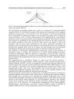
Fig. 4 shows that there may remain rather significant inhomogeneities in the temperature
distribution of particles in the bed. These inhomogeneities are decreasing with increasing
interparticle collision frequency therefore the particle-particle interaction play important
role in homogenization of temperature inside the population of particles.
10
-5
10
0
0
2
4
6
8
data1
data2
data3
data4
data5
data6
data7
σ
2
(τ)
τ
1.0 ·10
2
5.0 ·10
2
1.0 ·10
3
2.5 ·10
3
5.0 ·10
3
7.5 ·10
3
1.0 ·10
4
S
pp
Fig. 4. Time evolution of the variance of temperature distribution of the particle population
Fig. 5 presents the time evolution of the temperatures of characteristic parts of the bubbling
bed, i.e. mean temperature of particles, the temperatures of the bubble phase and the gas in
the emulsion phase, as well as the temperatures of the wall and liquid in the jacket. In this
case the input temperature of gas was 180 ºC and the initial temperature of gas in the
emulsion and bubble phases were of the same values. It is seen how the temperature
profiles vary in interconnections of the different parts of the bed. In steady state, under the
given heat transfer resistance conditions of the particle population, the wall and liquid is
heated practically only by the gas in the emulsion phase while the bubbles flow through the
bed without losing heat assuring only the well stirred state of the emulsion phase.
10
-5
10
0
0
50
100
150
200
τ
T(τ)
T
e
T
w
T
l
T
b
T
Fig. 5. Time evolution of the temperatures of characteristic parts of the bubbling bed in inter-
relations with each other
Heat Transfer - Mathematical Modelling, Numerical Methods and Information Technology
430
In Fig. 5, bubble temperature transient is shown only for the bed output indicating here a
rather sharp front. Naturally, the temperature front of bubbles evolves progressively along
the bed as it shown in Fig. 6 at different axial coordinates showing that in transient states the
bubble phase also plays role in the heating process.
However the bubble evolves transient states
10
-6
10
-4
10
-2
10
0
10
2
80
100
120
140
160
180
data1
data2
data3
data4
data5
T
b
(ξ)
τ
0.1
0.3
0.6
0.8
1.0
ξ
Fig. 6. Progression of evolution of the temperature front of the bubble phase along the axial
coordinate of the bed
10
-5
10
0
20
25
30
35
40
45
data1
data2
data3
data4
τ
T
0.5
1.0
5.0
10.0
S
pw
Fig. 7. Time evolution of the mean temperature of particle population as a function of the
particle-wall collision frequency
Eq. (76) shows clearly that when the number of particles is constant, i.e. under steady state
hydrodynamic conditions interparticle heat transfer does not influence the mean value of
temperature of the particle population but, as it is demonstrated by Fig. 4, it affects the
variance. However, as Fig. 7 gives an evidence of that the mean value of temperature of the
particle population depends on the particle-wall collision frequency. This figure indicates
also that because of the heat transfer interrelations of different parts of the bed oscillations
may arise in the transient processes which becomes smoothed as the particle-wall collision
frequency decreases. At the same time, in this case the particle-wall collision frequency
affects also the variance of temperature distribution of the particle population as it is shown
in Fig. 8. It is seen that with increasing particle-wall collision frequency the variance de-
Population Balance Model of Heat Transfer in Gas-Solid Processing Systems
431
creases. i.e. increasing particle-wall heat transfer intensity gives rise to smaller inhomoge-
neites in the temperature distribution of particles.
10
-5
10
0
0
2
4
6
8
10
data1
data2
data3
data4
τ
σ
2
(τ)
0.5
1.0
5.0
10.0
S
pw
Fig. 8. Time evolution of the variance of temperature distribution of the particle population
as a function of the particle-wall collision frequency
9. Conclusion
The spatially distributed population balance model presented in this chapter provides a tool
of modeling heat transfer processes in gas-solid processing systems with interparticle and
particle-wall interactions by collisions. Beside the gas-solid, gas-wall and wall-environment
heat transfers the thermal effects of collisions have also been included into the model. The
basic element of the model is the population density function of particle population the
motion of which in the space of position and temperature variables is governed by the
population balance equation.
The population density function provides an important and useful characterization of the
temperature distribution of particles by means of which temperature inhomogeneities and
developing of possible hot spots can be predicted in particulate processes. In generalized
form the model can serve for cognitive purposes but by specifying appropriate symmetry
conditions useful applicative, i.e. purpose-oriented models can be obtained.
The second order moment equation model, obtained from the infinite hierarchy of moment
equations generated by the population balance equation, as an applicative model can be
applied successfully for analyzing the thermal properties of gas-solid processing systems by
simulation. The first two moments are required to formulate the heat balances of the
particulate system while the higher order moments are of use for characterizing the process
in more detail.
Applicability of the second order moment equation model was demonstrated by modeling
and studying the behavior of bubbling fluidization by numerical experiments. It has proved
that collision particle-particle and particle-wall heat transfers contribute to homogenization
of the temperature of particle population to a large extent. The particle-particle heat transfer
no affects the mean temperature of particle population and, in fact, no influences any of
temperatures of the system whilst the particle-wall heat transfer collisions exhibits
significant influence not only on the steady state temperatures but on the transient processes
of the system as well. It has been demonstrated that the second order moment equation
Heat Transfer - Mathematical Modelling, Numerical Methods and Information Technology
432
model can be effectively used to analyze both the dynamical and steady state processes of
bubbling fluidization
10. Acknowledgement
This work was supported by the Hungarian Scientific Research Fund under Grant K 77955.
11. Symbols
a – surface area, m
2
c – specific heat, J kg
-1
K
-1
D – dispersion coefficient, m
2
s
-1
, bed diameter, m
e – coefficient of restitution
f – probability density function
h – enthalpy, J; heat transfer coefficient W m
-2
K
-1
K – aggregate rate coefficient of heat transfer
k – thermal conductivity, W m
-1
K
-1
m – mass, kg
m
k
– normalized k
th
order moment of particle temperature
N – number of particles, no m
-3
n – population density function, no m
-3
K
-1
p
p
– weight parameter
p
w
– weight parameter
Pe – Peclet number
q – volumetric flow rate, m
3
s
-1
S – frequency of collisions, s
-1
T – temperature, K
t – time, s
u – linear velocity, m s
-1
v – volume, m
3
V – volume, m
3
x – axial coordinate, m
t mean residence time, s
. mean value
1 - Heaviside function
Greek symbols
β
– aggregate heat transfer coefficient
ρ
– density, kg m
-3
δ
– Dirac delta function
κ
– parameter
ω
– random variable characterizing collision heat transfer
μ
k
– k
th
order moment of particle temperature
ε
– volumetric fraction
ξ – dimensionless axial coordinate
τ – dimensionless time
Population Balance Model of Heat Transfer in Gas-Solid Processing Systems
433
σ
2
– variance of the temperature of particle population
Subscripts and superscripts
c – critical value
e – emulsion phase; coefficient of restitution
g – gas
in – input
b – bubble
max – maximal value
min – minimal value
p – particle
pg – particle-gas
pp – particle-particle
pw – particle-wall
w – wall
wb – wall-gas
12. References
Bi, H.T., Ellis, N., Abba, A. & Grace, J.R. (2000). A state-of-the-art review of gas-solid tur-
bulent fluidization. Chem. Eng. Sci., 55, 4789-4825.
Boulet, P, Moissette, S., Andreaux, R. & Osterlé, B., (2000). Test of an Eulerian–Lagrangian
simulation of wall heat transfer in a gas–solid pipe flow. Int. J. Heat Fluid Flow, 21,
381-387.
Chagras, V., Osterlé, B. & Boulet, P. (2005). On heat transfer in gas-solid pipe flows: Effects
of collision induced alterations on the flow dynamics. Int. J. Heat Mass Transfer, 48,
1649-1661.
Chang, J. & Yang, S. (2010). A particle-to-particle heat transfer model dense gas-solid
fluidi-zed bed of binary mixtures. Chem. Eng. Res. Des.,
doi:10.1018/j.cherd.2010.08.004
Delvosalle, C. & Vanderschuren, J., (1985). Gas-to-particle and particle-to-particle heat
transfer in fluidized beds of large particles. Chem. Eng. Sci., 40, 769-779.
Gardiner, C.W.,(1983). Handbook of Stochastic Methods. Springer-Verlag, Berlin.
Gidaspow, D. (1994). Multiphase Flow and Fluidization. Boston: Academic Press.
Lakatos, B.G., Mihálykó, Cs. & Blickle, T. (2006). Modelling of interactive populations of
disperse system. Chem. Eng. Sci., 61, 54-62.
Lakatos, B.G., Süle, Z. & Mihálykó, Cs. (2008). Population balance model of heat transfer in
gas-solid particulate systems. Int. J. Heat Mass Transfer, 51, 1633-1645.
Mansoori, Z., Saffar-Avval, M., Basirat-Tabrizi, H., Ahmadi, G. & Lain, S. (2002). Thermome-
chanical modeling of turbulent heat transfer in gas-solid flows including particle
col-lisions, Int. J. Heat Fluid Flow Transfer, 23, 792-806.
Mansoori, Z., Saffar-Avval, M., Basirat-Tabrizi, H., Dabir, B. & Ahmadi, G. (2005). Inter-
particle heat transfer in a riser of gas-solid turbulent flows. Powder Technol., 159,
35-45.
Martin, H., (1984). Heat transfer between gas fluidized bed of solid particles and the surfaces
of immersed heat transfer exchanger elements. Chem. Eng. Proc. 18, 199-223.
Heat Transfer - Mathematical Modelling, Numerical Methods and Information Technology
434
Mihálykó, Cs., Lakatos, B.G., Matejdesz, A. & Blickle, T., (2004). Population balance model
for particle-to-particle heat transfer in gas-solid systems. Int. J. Heat Mass Transfer,
47, 1325-1334.
Molerus, O., (1997). Heat transfer in moving beds with a stagnant interstitial gas. Int. J. Heat
Mass Transfer, 40, 4151-4159.
Ramkrishna, D. (2000). Population Balances. Theory and Applications to Particulate Systems in
Engineering. San Diego: Academic Press.
Schlünder, E.U., (1984). Heat transfer to packed and stirred beds from the surface of
immersed bodies. Chem. Eng. Proc. 18, 31-53.
Sobczyk, K., (1991). Stochastic Differential Equations with Applications to Physics and
Engeneering. Kluwer Academic, Amsterdam.
Süle, Z., Lakatos, B.G. & Mihálykó, Cs., (2009). Axial dispersion/population balance model
of heat transfer in turbulent fluidization. in: Jeżowski J., and Thullie, J., (Eds) Proc.
19th ESCAPE. Comp. Aided Chem. Eng. 26, Elsevier, Amsterdam:, 815-820.
Süle, Z., Lakatos, B.G. & Mihálykó, Cs., (2010). Axial dispersion/population balance model
of heat transfer in turbulent fluidization. Comp. Chem. Eng., 34, 753-762.
Süle, Z., Mihálykó, Cs. & Lakatos, B.G. (2006). Modelling of heat transfer processes in
particulate systems. in: W. Marquardt, C. Pantelides (Eds), Proc. 16th ESCAPE and
9th ISPSE. Comp-Aided Chem. Eng. 21A, Elsevier, Amsterdam, 589-594.
Süle, Z., Mihálykó, Cs. & Lakatos, G.B., (2008). Population balance model of gas-solid
fluidized bed heat exchangers. Chem. Proc. Eng., 29, 201-213.
Sun, J. & Chen, M.M., (1988). A theoretical analysis of heat transfer due to particle impact.
Int. J. Heat Mass Transfer, 31, 969-975.
Thompson, M.L., Bi, H. & Grace, J.R. (1999). A generalized bubbling/turbulent fluidized-
bed reactor model. Chem. Eng. Sci., 54, 2175-2185.
Vanderschuren, J. & Delvosalle, C., (1980). Particle-to-particle heat transfer in fluidized bed
drying. Chem. Eng. Sci., 35, 1741-1748
17
Synthetic Jet-based Hybrid Heat Sink for
Electronic Cooling
Tilak T Chandratilleke, D Jagannatha and R Narayanaswamy
Curtin University
Australia
1. Introduction
Modern lifestyle is increasingly dependant on a myriad of microelectronic devices such as
televisions, computers, mobile phones and navigation systems. When operating, these
devices produce significant levels of internal heat that needs to be readily dissipated to the
ambient to prevent excessive temperatures and resulting thermal failure. With inadequate
cooling, internal heat builds up within electronic packages to raise microchip temperatures
above permitted thermal thresholds causing irreparable damage to semiconductor material.
Devices would then develop unreliable operation or undergo complete thermal breakdown
from overheating with reduced working life. In electronic industry, 55 percent of failures
are attributed to overheating of internal components. Therefore, effective dissipation of
internally generated heat has always been a major technical consideration for
microelectronic circuitry design in preventing overheating and subsequent device failure.
In recent years, the modern microelectronic industry has shown a dramatic growth in
microprocessor operating power, circuit component density and functional complexity
across the whole spectrum of electronic devices from small handheld units to powerful
microprocessors, as evidenced by Figs. 1 and 2.
0
50
100
150
200
250
300
350
400
2000 2002 2004 2006 2008 2010 2012 2014 2016 2018 2020
Year
Chip Power Dissipation (W)
Maximum
Minimum
Fig. 1. Evolution of chip power dissipation (Chu, 2003)
Heat Transfer - Mathematical Modelling, Numerical Methods and Information Technology
436
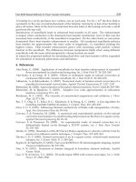
Fig. 2. Component density and maximum processing performance trends
Source: International Technology Roadmap for Semiconductors (ITRS)-2008
These industry trends into the future are very much poised to increase the microprocessor
internal heat loads well beyond the capabilities of established cooling technologies making
them rapidly inadequate to meet the predicted intense heat dissipation demand. For this,
the future of electronic product design and development is critically hinged upon the
availability of more enhanced or effective heat dissipation methods. This chapter presents a
novel electronic cooling technique to address this current technological shortfall.
1.1 Thermal management techniques
In electronic system design, thermal management involves the use of appropriate heat
transfer technology to remove internally generated heat as effectively as possible to retain
component temperatures within safe operating limits. Literature identifies two specific
stages for thermal management process. The first stage considers heat conduction from
integrated circuit and to the encased package surface while the second stage deals with the
global rejection of heat from the system to the ambient. Thus, the thermal management
technologies can be broadly divided into two groups: (a) Technologies for enhancing heat
flow integrated circuits to package surfaces, such as thermoelectric devices and heat pipes;
(b) Technologies for enhancing heat exchange between the electronic package and the
ambient, such as heat sinks, microchannels and fluid jet cooling. The work entailed in this
chapter contributes to the latter group.
Thermal management techniques can be passive or active mechanisms. Passive techniques
(e.g. convective heat sink, heat pipe) do not require additional energy input for operation;
however their poor heat transfer capabilities overshadow this advantage. Intrinsically,
active techniques (e.g. micro-refrigerator, microchannel heat sink) have better thermal
performance, but are discredited by the extra operating power needs or higher pressure
drop penalties. In spite of these limitations, active heat sinks firmly remain the most
thermally effective and preferred option for future high-powered microcircuitry cooling
applications, whilst passive heat sinks are being confined to low heat loads.
As an active thermal management technique, heat sinks utilising micro or mini fluid
passages are highly regarded by the electronic industry to be the current frontier technology
for meeting high heat dissipation demand. It has been estimated (Palm, 2001) that the
Synthetic Jet-based Hybrid Heat Sink for Electronic Cooling
437
industry application of microchannel heat sinks would increase by 10 fold within the next 5
years in view of its high cooling potential achievable. A major drawback of microchannel
heat sinks is their inherently high pressure drop characteristics, particularly at increased
fluid flow rates necessary to deliver large cooling loads.
Motivated by the application needs of the electronic industry, the research on microchannel
thermal behaviour has extensively progressed through numerical modelling and
experimentation (Lee et al., 2005; Qu & Mudawar, 2002; Lee & Garimella, 2006). The primary
focus of such research has been to predict and validate thermal performance. Much less
attention has been directed for developing effective thermal enhancement strategies for
micro-scale channels. The use of internal fins in microchannels has been identified to be a
very promising passive enhancement option for single phase mini and microchannels
(Steinke & Kandlikar, 2004) although the increased pressure drop is a design concern. This
is well supported by a comprehensive treatment on such internal fins and possibilities for
thermal optimisation (Narayanaswamy et al., 2008).
Whilst passive enhancement techniques have conceivable application potential, active
methods are known to be more thermally effective and relevant for future cooling needs.
Active heat sink systems can be made a more attractive proposition if an innovative
approach could reduce operating power or pressure penalties without impacting on thermal
performance. A hybrid heat sink incorporating a pulsating fluid jet offers a unique thermal
enhancement option of this nature, as discussed below.
The proposed method utilises a special pulsing fluid jet mechanism called synthetic jet for
enhancing convective heat transfer process in fluid flow channels of an active heat sink.
This arrangement operates with unprecedented thermal performance but without the need
for additional fluid circuits or incurring pressure drop, which are key features that set it
apart from other traditional methods.
1.2 Synthetic (pulsed) jet mechanism and its behaviour
A synthetic jet is created when a fluid is periodically forced back and forth through a
submerged orifice in such a way that the net mass discharged through the orifice is zero
while generating large positive momentum in the jet fluid stream. A simple synthetic jet
actuator is schematically shown in Fig. 3.
Fig. 3. Schematic diagram of a synthetic jet actuator
Heat Transfer - Mathematical Modelling, Numerical Methods and Information Technology
438
The actuator comprises of an oscillating diaphragm that resides within a cavity and induces
a periodic fluid flow through a submerged orifice. In its upward motion, the diaphragm
forces the fluid to be squirted out through the orifice with very large momentum. During
downward motion, the diaphragm draws low-momentum fluid from the surroundings back
into the cavity. Thus, over an operating cycle, the jet delivers very high net outflow of fluid
momentum with no net change of fluid mass within the cavity. Owing to this unique
feature, this jet flow is known as a synthetic jet or Zero-Net-Mass-Flux (ZNMF) jet (Smith &
Glezer, 1998).
A synthetic jet impinging on a heated surface is capable of generating very high localised
cooling because of the large fluid momentum imparted. As evident, this mechanism does
not require additional fluid circuits to operate or introduce extra pressure drop to the flow
field, which are major technical advantages. Synthetic jets are formed from the same
working fluid in which they are deployed. This has significant benefits for microelectronic
circuitry where air-cooling is preferred to prevent possible electrical short-circuiting and
leakage faults. Smaller synthetic jet size permits high-flux clustered cooling without the
need for fluid circulatory circuits unlike steady jets thereby reducing energy consumption
and production cost. The diaphragm motion is practically achieved by a piston or acoustic
loudspeaker or piezo-electric unit to obtain the desired amplitude or frequency.
Synthetic jets have been primarily studied in the context of pulsating jet actuators impinging
on submerged surfaces in quiescent fluid media without any cross flow interactions. Such
studies indicate outstanding thermal characteristics for localised cooling with synthetic jets.
Significant examples of those are by (Campbell et al., 1998) who have demonstrated that
synthetic air micro jets were effective cooling arrangements for laptop processors.
(Mahalingam & Rumigny, 2004) illustrated the effectiveness of synthetic jets for high power
electronic cooling by developing an integrated active heat sink based on this mechanism.
(Gillespie et al., 2006) provide the results of an experimental investigation of a rectangular
synthetic jet impinging on a unconfined heated plate exposed to the ambient where
characteristics of the jet and plots of Nusselt numbers are available. (Pavlova & Amitay,
2006) have conducted experimental studies on impinging synthetic jets for constant heat
flux surface cooling and compared its performance with a steady or continuous jet where
there are no velocity fluctuations. They concluded that for the same Reynolds number,
synthetic jets are three times more effective than the corresponding continuous jets.
(Utturkar et al., 2008) experimentally studied synthetic jet acting parallel to the flow within a
duct. The synthetic jet was placed at the surface of a heated duct wall and aligned with the
bulk flow such that the jet assisted the bulk flow. In a 100 mm square channel with a 30 mm
synthetic jet, they obtained a 5.5 times enhancement for a bulk flow velocity 1 m/s. This
enhancement reduced to approximately 3 times when the bulk velocity was increased to 2.0
m/s. Their numerical simulation matched reasonably well with only one test condition.
(Go & Mongia, 2008) experimentally studied the effect of introducing a synthetic jet into a
low speed duct flow to emulate the confined flow within in a typical notebook. The
interaction of these two flows was studied using particle image velocimetry (PIV) and
measurements on the heated duct wall. They found that the synthetic jet tends to retard or
block the duct flow while a 25 percent increase in thermal performance was observed.
Numerical studies on thermal performance of synthetic jet with cross flow interaction are
also very limited in published literature. Such significant work is presented by (Timchenko
et al., 2004) who investigated the use of a synthetic jet induced by a vibrating diaphragm to
enhance the heat transfer in a 200 μm microchannel. Their two-dimensional (2-D) transient
Synthetic Jet-based Hybrid Heat Sink for Electronic Cooling
439
simulation considered the jet acting in cross-flow to the bulk flow in a channel with the
diaphragm executing a parabolic motion. They observed a 64 percent improvement in
cooling at the impinging wall for the flow conditions used. Despite the recognised
significance of flow turbulence in synthetic jet flows, their analysis however did not include
an appropriate turbulence model in the simulation.
In a recent study, (Erbas & Baysal, 2009) conducted computational work of a synthetic jet
actuator in a two-dimensional channel to assess its thermal effectiveness on a heated surface
protruding into the fluid as a step. They varied the number of actuators, placement and
phasing of the membrane concluding that the heat transfer rate would increase with the
number of jets, appropriate jet spacing, the use of nozzle-type orifice geometry and 180
o
out
of phase jet operation. However, the investigation did not examine the influence of cross
flow on the thermal performance.
Performing a detailed parametric study, the work presented in this chapter evaluates and
quantifies the thermal enhancement benefits for fluid flow through an electronic heat sink
from a synthetic jet actuator mechanism. This hybrid arrangement is numerically simulated
to obtain heat and fluid flow characteristics from which unique behaviour of the jet and
cross-flow interaction is analysed. The degree of thermal enhancement is with respect to a
heat sink unassisted by synthetic jet flow.
2. Synthetic jet hybrid heat sink - numerical model development
2.1 Geometrical description and operation
The present study proposes a hybrid arrangement for electronic cooling utilising a synthetic
jet intercating with conventional fluid stream in heat sink, as depicted in Fig. 4. The
synthetic jet is induced by a cavity fitted with an oscillating diaphragm that is mounted on
the heat sink. The oscilatory motion of the diaphragm injects a pulsating fluid jet through a
small orifice into the fluid stream in the heat sink’s flow passage. The diaphragm moving
inwards, ejects a high-speed jet that creating a pair of counter-rotating vortices in the
surrounding fluid. When retreating, the diaphragm draws fluid back into the cavity. The
Fig. 4. Schematic diagram of synthetic jet mounted on heat sink in cross-flow configuration
Heat Transfer - Mathematical Modelling, Numerical Methods and Information Technology
440
fluid jet and its vortices interact in cross-flow manner with the fluid stream in heat sink’s
flow passage and perform periodic impingement on the heated wall. The operation over
one diaphragm cycle is such, the jet delivers an intense momentum fluid outflow with zero
net mass output through the orifice, hence complying with “synthetic jet” or Zero-Net-
Mass-Flux jet condition.
The vortex formation associated with synthetic jet is governed by the non-dimensional
groups Reynolds number (Re) and Stokes number (S), and occurs under the parametric
condition of Re/S
2
>K, where the constant K ≈ 1 for two-dimensional jets and 0.16 for axi-
symmetric synthetic jets (Holman et al., 2005). Through due consideration of this
requirement, the geometrical dimensions were selected for the 2-dimensional analytical
model attempted. They are: orifice width d
o
= 50 μm, orifice length h
o
= 50 μm, channel
height H = 500 μm, channel length D = 2250 μm, heater length L = 750 μm, cavity width
d
c
= 750 μm and cavity height h
c
= 500 μm. This selection was checked for its compliance
with the continuum mechanics for the scale of the attempted problem using Knudsen
number Kn, which is the ratio of the molecular free path length to representative length.
2.2 Governing equations
This study investigates the heat transfer characteristics of low Reynolds number turbulent
synthetic jets operating in a confined region while interacting with fluid flow in heat sink.
Applicable governing equations for the analysis are: the Navier-Stokes equations; the
continuity equation and the energy equation subject to applied boundary conditions. Air is
assumed to be an incompressible Newtonian fluid although compressibility effects are
considered later. These equations are as follows:
Continuity
0
y
v
x
u
=
∂
∂
+
∂
∂
(1)
x-momentum
⎟
⎟
⎠
⎞
⎜
⎜
⎝
⎛
∂
∂
+
∂
∂
μ+
∂
∂
−=
∂
∂
+
∂
∂
+
∂
∂
2
2
2
2
y
u
x
u
x
p
y
u
v
x
u
u
t
u
(2)
y-momentum
⎟
⎟
⎠
⎞
⎜
⎜
⎝
⎛
∂
∂
+
∂
∂
μ+
∂
∂
−=
∂
∂
+
∂
∂
+
∂
∂
2
2
2
2
y
v
x
v
y
p
y
v
v
x
v
u
t
v
(3)
Energy
()()
TkpEU)E(
t
2
eff
∇++ρ⋅−∇=ρ
∂
∂
(4)
where k
eff
is the effective conductivity and E is the total energy.
The local Nusselt number Nu (x,t) wherein the local wall heat transfer coefficient h is
embedded, describes the convective heat transfer between the heated surface and the
synthetic jet flow. Using orifice width d
o
as the characteristic length, this is defined as,
T
d
y
T
k
hd
)t,x(Nu
o
f
o
Δ∂
∂
== (5)
Synthetic Jet-based Hybrid Heat Sink for Electronic Cooling
441
The Nusselt number is evaluated from the local surface normal temperature gradient,
T
y
∂
∂
and the temperature difference ΔT = (T
w
– T
b
) where T
w
is the local wall temperature and T
b
is the average bulk fluid temperature the in the fluid domain.
2.3 Solution domain and boundary conditions
The 2-dimensional numerical simulation was formulated using the computational fluid
dynamics software FLUENT. A structured mesh was used in the solution domain, as shown
in Fig. 5 using GAMBIT mesh generation facility. The grid dependency of results was tested
by observing the changes to the time-averaged velocity fields in the solution domain for
varied grid sizes of 14000 (coarse), 48072 (medium) and 79000 (fine). In view of the moving
mesh integrity and CPU time, the most appropriate grid size was found to be 48072 cells for
a five percent tolerance between successive grid selections. In capturing intricate details of
the jet formation and flow separation, the grid density in the vicinity of the orifice was
refined to have 14 grid cells in the axial direction and 20 in the transverse direction.
Fig. 5. Computational grid for solution domain (Inset shows enlarged view of the marked
region)
Adiabatic conditions were applied at the cavity walls and the diaphragm while the heater
surface was maintained at an isothermal temperature of 360 K. The (left) inlet to the heat
sink flow passage was treated as a known constant velocity boundary while the (right) flow
outlet was treated as pressure outlet boundary. It was assumed that the working fluid air is
incompressible and has an inlet temperature of 300 K with constant thermodynamic
properties under standard atmospheric conditions.
Arising from small geometrical length scales, synthetic jets generally tend to have small
operating Reynolds numbers making flow turbulence seemingly unimportant. However, the
oscillating nature of the flow may give rise to intense localised perturbations. In handling
the wide flow variations, the Shear-Stress-Transport (SST) k-ω turbulence model was
invoked in the model to provide an accurate representation of the near-wall region of wall-
bounded turbulent flows. Initially, a 3 percent turbulence intensity was applied at the
outlets, thereafter the flow was allowed to develop on its own through the inherent
instabilities. The y+ and y* value in the wall region were found to be approximately 1,
confirming that the near-wall mesh resolution is in the laminar sublayer.
Heat Transfer - Mathematical Modelling, Numerical Methods and Information Technology
442
2.4 Initial conditions and solution methodology
The initial (t = 0) position of the diaphragm was taken to be at the bottom of the cavity. A
special User Defined Function (UDF) incorporating Dynamic-layering technique (FLUENT,
2004) was formulated and combined with the FLUENT solver to describe the periodic
diaphragm movement. For this, the diaphragm displacement was expressed as y = A sin
(ωt), where A is the diaphragm amplitude, ω is the angular frequency and t is time.
A segregated solution method with implicit solver formulation in FLUENT was used as the
numerical algorithm while the Second-order discretisation schemes were employed for
density, momentum, pressure, kinetic energy, specific dissipation rate and energy. The
Pressure-Implicit with Splitting of Operators (PISO) scheme was used for pressure-velocity
coupling. The bulk temperature of air at every time step was calculated using an UDF while
the updated bulk temperature was fed back to the simulation for calculating local heat
transfer coefficient and Nusselt number.
The jet Reynolds number (Re
c
) was calculated based on the jet characteristic velocity U
c
,
which is defined by (Smith & Glezer, 1998) as,
∫
==
2
T
0
0sc
dt)t(u
T
1
fLU
(6)
where u
o
(t) is the jet velocity at the orifice discharge plane, ½T is the jet discharge time or
half period of diaphragm motion, and L
s
is the stroke length (defined as the discharged fluid
length through orifice during the inward diaphragm stroke).
Considering the operating range given in Table 1, the unsteady, Reynolds-averaged Navier-
Stokes equations and the energy equation were solved to obtain the simulated thermal
behaviour of the synthetic jet hybrid heat sink. The simulation was carried out using 720
time steps per cycle wherein 20 sub-iterations were performed within each time step.
Parameter Range
Heat sink inlet flow velocity, V
i
(m/s) 0, 0.5, 1.0, 2.0
Diaphragm frequency, f (kHz) 10
Diaphragm Amplitude, A (μm)
0,25,50,75,100
Jet Reynolds Number, Re
c
15, 30, 46, 62
Distance from orifice to heated wall, H/d
o
10
Table 1. Parametric range for numerical simulation
At each time step of a cycle, the internal iterations were continued until the residuals of
mass, momentum, turbulence parameters (k and ω) were reduced below 10
-3
and energy
residuals were reduced below 10
-6
, which is the convergence criterion for the computation.
Data were extracted at every twentieth time step giving 36 data points per cycle. It was
observed that 10 diaphragm cycles would be sufficient to achieve quasi-steady operating
conditions in this flow geometry. To increase accuracy, a 2D-double precision solver was
used to solve the governing equations for heat and fluid flow.
Synthetic Jet-based Hybrid Heat Sink for Electronic Cooling
443
3. Results and discussion
3.1 Model validation
The model validation for the present simulation was carried out by formulating a separate
synthetic jet model to match the dimensions used in the published work of (Yao et al., 2006).
These results were extensively incorporated in NASA Langley Research Centre Workshop
(CFDVAL2004) in assessing the suitability of turbulence models for synthetic jet flows. The
results of this workshop concluded that the Shear-Stress-Transport (SST) k-ω turbulence
model works best among the URANS models for jet flows.
For validation, the predicted axial (y-velocity) was compared with the experimental jet
velocities measured by (Yao et al., 2006) using the techniques of Particle Image Velocimetry
(PIV), Hot wire anemometry and Laser Doppler Velocimetry (LDV). This comparison is
shown in Fig. 6, where it is seen that the present simulation agreed very well with the
experimental data validating the model and its accuracy.
-30
-20
-10
0
10
20
30
40
0 50 100 150 200 250 300 350
Phase,deg
Y-vel, m/s
PIV
LDV
Hot-Wire
Present study
Fig. 6. Comparison of predicted axial/y-velocity of present work with the (PIV, LDV, Hot-
wire) experimental data of (Yao et.al., 2006) at 0.1 mm from the orifice exit plane ( f = 444.7
Hz, A=1.25 mm)
3.2 Velocity and fluid flow characteristics
For the synthetic jet operating frequency of 10 kHz and amplitude of 25 μm, Fig. 7 illustrates
the diaphragm displacement and the jet discharge velocity over one cycle completed in 0.1
milliseconds. This jet velocity fluctuation resembles a sinusoidal pattern and verifies the net
fluid mass discharge through the orifice to be zero for the synthetic jet operation.
Figs. 8 (a) and 8 (b) show typical time-lapsed velocity contours within the solution domain
respectively for two separate cases of synthetic jet operation: (a) with stagnant fluid within
heat sink (b) with flowing fluid in heat sink passages. It is seen that the simulation very well
captures the intricate details of the synthetic jet discharge, subsequent vortex formation and
the flow interaction between the jet and the cross-flow heat sink fluid stream.
During the diaphragm upward motion, a high-velocity fluid jet is discharged through the
cavity orifice into the flow passage. Determined by diaphragm amplitude, sufficiently
strong jet momentum enables the jet to penetrate the micro passage flow to reach the heated
Heat Transfer - Mathematical Modelling, Numerical Methods and Information Technology
444
-30
-20
-10
0
10
20
30
0 255075100
Flow Time, t (μs)
Diaphragm Amplitude, A (μm)
-16
-12
-8
-4
0
4
8
12
16
Axial Velocity (m/s)
Diaphragm Amplitude
Axial Velocity
Fig. 7. Diaphragm displacement and jet velocity over one cycle at A = 25 μm and f = 10 kHz
(upper) wall within the time up to t = ½T at the peak diaphragm displacement. In the
figures, the formation of synthetic jet vortices is clearly visible during this initial phase of
sequence. The flow patterns exhibits symmetry in Fig. 8 (a) while the cross-flow drag
imparted by the fluid stream in heat sink passage gives rise to asymmetry in Fig. 8 (b) where
the jet is swayed in the streamwise direction. For t > ½T, the diaphragm retreats from its
peak displacement to complete the cycle. During this final phase, the jet mechanism draws
fluid back into the cavity. Meanwhile, already formed synthetic jet vortices are washed
downstream by the fluid flow in heat sink passage.
Fig. 8(b) reveals that, even with the flow through heat sink, the synthetic jet still exhibits all
of its fundamental characteristics corresponding to stagnant flow conditions. The synthetic
jet periodically interrupts the flow through heat sink and breaks up the developing thermal
and hydrodynamic boundary layers at the heated top wall. This cross-flow interaction
creates steep velocity and temperature gradients at the heated surface as long as jet
impingement occurs. This pulsating flow mechanism therefore leads to improved thermal
characteristics in the synthetic jet-mounted heat sink.
The skewness in the jet discharge velocity profile is recognised as a prime factor in the
process of synthetic jet vortex formation at the orifice. Fig. 9 shows the velocity vectors near
jet orifice at t=T/2 (point of maximum jet expulsion) for two heat sink cross-flow velocities,
V
i
= 0.5 m/s and 2.0 m/s. The figure clearly indicates the existence of lateral flow velocities
across the orifice mouth. This fluid motion induces fluid recirculation or entrainment within
the orifice passage and its vicinity, encouraging the jet flow to diverge and form vortices.
As illustrated, for higher heat sink cross-flow velocity, the fluid entrainment at the orifice
becomes vigorous, hence producing stronger synthetic jet vortices.
The nature of synthetic jet movement through heat sink’s cross flow is depicted in Fig. 10,
where the axial jet velocity is plotted at several height elevations in the heat sink flow
passage above the orifice plane. These velocity profiles are at t = T/2, where the diaphragm
displacement is maximum with f = 10 kHz and A = 50 µm. The velocity profiles for a
synthetic jet operating in stagnant fluid medium are also shown for comparison. These
figures show that, the heat sink cross-flow drag shifts the point of impingement
downstream of the flow passage with respect to jet operation in stagnant fluid. The jet
impingement velocity is also somewhat attenuated with the increased cross-flow velocity.
Synthetic Jet-based Hybrid Heat Sink for Electronic Cooling
445
Fig. 8. Time-lapsed velocity contours over one diaphragm cycle
Heat Transfer - Mathematical Modelling, Numerical Methods and Information Technology
446
Fig. 9 Velocity vectors near the orifice at time t=T/2 (maximum expulsion)
f = 10 kHz, A = 50 µm Note: Length of arrows and colours indicate velocity magnitude (m/s)
Synthetic Jet-based Hybrid Heat Sink for Electronic Cooling
447
Fig. 10. Channel cross-flow effect on jet propagation at f = 10 kHz and A = 50 µm
Heat Transfer - Mathematical Modelling, Numerical Methods and Information Technology
448
Fig. 11. Effect of diaphragm amplitude illustrated by velocity contours at t = ½ T
Relative strengths of the synthetic jet and the channel flow drag determine the extent of
cross-flow interference and the boundary layer disruption at the heated wall. This is
illustrated in Figs. 11(a) and 11(b) for heat sink flow velocities of 0.5 m/s and 1.0 m/s. It is
clearly evident that the increased cross-flow causes the jet to be swayed downstream
impeding the jet’s penetrating ability through the boundary layer to reach the heated wall.
Although this may reduce thermal benefits from jet impingement, the steeper velocity
gradients generated by the cross-flow and jet interaction at the heated wall may improve
forced convection heat transfer, leading to an increase in overall thermal performance.
Synthetic Jet-based Hybrid Heat Sink for Electronic Cooling
449
3.3 Thermal characteristics and heat transfer enhancement
The vortex generation process of the synthetic jet creates fluid flow structures very
conducive for heat transfer at the heated wall. This is effected by two major mechanisms: (a)
development of steep temperature gradients at the heated wall due to periodic thinning of
the thermal boundary layer arising from the synthetic jet and vortex impingement, and (b)
vigorous mixing of heated fluid layers at the wall with the bulk fluid, thus rapidly
transferring heat from the wall to the fluid. The temperature contours in Fig. 12 clearly
illustrate these two mechanisms. It is seen that, the regions of high fluid temperature are
essentially near the heated wall giving extremely high temperature gradients in that vicinity
and, it takes only a few cycles for the temperature dispersion into the bulk fluid.
Fig. 12. Temperature contours within the solution domain after 1, 5, 10, 15 and 20 cycles
Over one diaphragm cycle, Figs. 13 and 14 show the distribution of local Nusselt numbers at
the heated wall respectively, for the cases of with and without fluid flowing through the
heat sink flow passage.
In Fig. 13 for 0 < t < ½T, the Nusselt number remains very low. This value is more or less
similar to natural convection since the synthetic jet and vortices have yet to impinge on the
heated surface. Nusselt number shows a very rapidly increase to about 23 when t = 2T/3,
where the vortices begin to impinge on the heated surface. Subsequently, the Nusselt
number gently declines for t > 2T/3 as the jet recedes and diaphragm descends. On the
contrary, the variation of local Nusselt number in Fig. 14 shows a gentler rise over the entire
heated wall during the cycle because of the forced convection due to the fluid flow in heat
sink passage. At each time step, a peak is noticed in the distribution due to the jet and cross-
flow fluid interaction. At t = 2T/3, the Nusselt number shows its highest value of about 13
in the cycle. The position of this peak is shifted downstream because of the cross-flow fluid
drag swaying the impinging jet, as depicted in Figs. 8, 10 and 11.
Heat Transfer - Mathematical Modelling, Numerical Methods and Information Technology
450
0
5
10
15
20
25
-7-6-5-4-3-2-101234567
x/do
Local Nusselt Number,Nu
t = T/6
t = T/3
t = T/2
t = 2T/3
t = 5T/6
t = T
Fig. 13. Local Nusselt number at heated wall with stagnant flow in heat sink over one cycle
V
i
=0 m/s, f = 10 kHz and A = 50 μm
0
2
4
6
8
10
12
14
-7-6-5-4-3-2-101234567
x/do
Local Nusselt Number,Nu
t = T/6
t = T/3
t = T/2
t = 2T/3
t = 5T/6
t = T
Fig. 14. Local Nusselt number at heated wall with flowing fluid in heat sink over one cycle
V
i
=1 m/s , f = 10 kHz and A = 50 μm
In evaluating thermal benefits delivered by the synthetic jet interaction to heat sink passage,
a separate simulation was performed without the diaphragm movement while retaining all
the other geometrical and boundary conditions, as described before. For this pure forced
convection heat sink without the synthetic jet, Fig. 15 shows the variation of local Nusselt
number over the heated wall. It is observed that the Nusselt number asymptotically decays
from the leading edge of heated wall with the developing flow. Taking this pure forced
convection Nusselt number as the datum, the relative thermal performance of the hybrid
synthetic jet-heat sink is evaluated and presented in Fig. 16, where the degree of thermal
enhancement is expressed as the ratio of average heat sink Nusselt number with and
Synthetic Jet-based Hybrid Heat Sink for Electronic Cooling
451
without synthetic jet operation. It is evident that, for the tested parametric range, the
synthetic jet-based hybrid heat sink arrangement is capable of delivering up to 4.3 times
(V
i
=0.5 m/s) more heat transfer than an identical pure forced convection heat sink. Because
of the nature of synthetic jet mechanism, this degree of thermal enhancement is realised
without introducing additional net mass flow into the heat sink flow passage or needing
additional fluid circuits. These are recognised as major operational benefits of this hybrid
heat sink mechanism. Fig. 16 further shows that, higher cross-flow velocity impairs thermal
enhancement. This is a manifestation of channel flow drag swaying the synthetic jet
downstream preventing jet impingement. As the jet Reynolds number (or jet velocity or
diaphragm amplitude) is increased for a given cross-flow velocity, the thermal enhancement
rapidly increases when the jet is able to penetrate and reach the heated surface.
0
5
10
15
20
25
30
35
0 100 200 300 400 500 600 700
Heater Length (μm)
Local Nusselt Number, Nu
Vi = 0.5 (m/s)
Vi = 1 (m/s)
Vi = 2 (m/s)
Fig. 15. Variation of Nusselt number along the heater surface without synthetic jet
0.0
0.5
1.0
1.5
2.0
2.5
3.0
3.5
4.0
4.5
0 10203040506070
Jet Reynolds Number
Degree of Thermal Enhancement
0
5
10
15
20
25
Average Nusselt Number
Vi=0.5 (m/s)
Vi=1 (m/s)
Vi=2 (m/s)
Fig. 16. Degree of thermal enhancement in heat sink due to synthetic jet mechanism
Heat Transfer - Mathematical Modelling, Numerical Methods and Information Technology
452
For increasing channel velocity, Fig. 17 shows the thermal performance and pressure drop
of a heat sink without synthetic jet mechanism. If this heat sink were to deliver, for
example, 4.3 times thermal enhancement, it would require a 40-fold high velocity from a
datum value of 0.5 m/s. This would result in 70 times more channel pressure drop. On the
other hand, the synthetic jet-based hybrid heat sink achieves 4.3-fold thermal enhancement
with 0.5 m/s channel flow velocity with no increase in pressure drop. This clearly signifies
the thermal enhancement potential of this hybrid arrangement and its operational benefits.
0.0
0.5
1.0
1.5
2.0
2.5
3.0
3.5
4.0
4.5
0 3 6 9 12 15 18 21
Channel cross flow velocity, Vi (m/s)
Degree of Thermal enhancemen
t
0
20
40
60
80
100
120
140
Pressure Drop (Pa)
enhancement
pressure drop
Fig. 17. Degree of thermal enhancement and pressure drop without synthetic jet mechanism
3.4 Fluid compressibility effects on synthetic jet performance
The compressibility of air mass within the cavity may affect the jet discharge, thus the heat
sink performance, when the diaphragm operating frequency is varied. In examining this,
two identical simulations are carried out and the results are compared. The first case is
performed assuming constant air density, so that the fluid compressibility is totally
eliminated. In the second case, the fluid density is taken to be dependant on local pressure
in the solution domain with all the other simulation parameters being identical.
For the analyses with and without air compressibility, Fig. 18 illustrates the variation of
Nusselt number with diaphragm frequency. The Nusselt numbers for both cases closely
follow each other and increase almost linearly up to about 20 kHz. Beyond this, the Nusselt
number predicted by the compressibility analysis quickly deviates and indicates a drop in
magnitude while the incompressible Nusselt number continues to grow. The former
behaviour shows a minimum at a frequency of around 80 kHz in heat sink with stagnant
channel flow. At this frequency, the fluid discharge through the orifice is observed to cease.
This is attributed to the simultaneous expulsion and ingestion of air neutralising the flow
though the orifice or formation of standing waves. Therefore, a temporary breakdown
occurs in the synthetic jet thermal effectiveness. However, the performance readily recovers
beyond this critical diaphragm frequency. When the cross-flow is introduced, this limiting
frequency is dramatically reduced to about 40 kHz at 0.5 m/s channel velocity. It is thought
to be due to choking of the orifice arising from the increased flow entrainment at the orifice
passage, as previously explained with respect to Fig. 9.
Synthetic Jet-based Hybrid Heat Sink for Electronic Cooling
453
Fig. 18. Effect of compressibility on synthetic jet heat sink characteristics
4. Conclusions
This study has successfully demonstrated a novel technique for enhancing thermal
performance of pure convective heat sinks in electronic cooling applications. The proposed
method utilises a periodic fluid jet called “Synthetic Jet” that is injected into the heat sink’s
flow channel with a large fluid momentum but with zero averaged fluid mass discharge.
The interaction between the jet and the fluid flow in channel creates excellent thermal
characteristics at the heated wall thereby enhancing the heat sink’s thermal performance. In
the tested range, this synthetic jet-based heat sink delivers up to 4.3 times more wall heat
transfer compared to an identical pure convection heat sink. Under incompressibility
conditions, the thermal performance continues to grow with the increased diaphragm
frequency. When the fluid compressibility is accounted for, the thermal performance
temporarily falls upon reaching a certain frequency and then recovers with further
frequency increase. This hybrid flow system has a unique ability to achieve excellent heat
transfer rates without higher channel flow velocities in heat sink or causing pressure drop
increases in flow passage. Also, this mechanism does not require additional fluid circuits to
achieve such high heat transfer rates. These are identified as key operational attributes that
set it apart from other thermal enhancement strategies.
5. References
Chu, R C. (2003). The Perpetual Challenges of Electronic Cooling Technology for Computer
Product Applications-from laptop to supercomputers. National Taiwan University
Presentation, November 12, 2003, Taipei, Taiwan.
Campbell, J S.; Black, W Z. & Glezer, A. (1998). Thermal Management of a laptop Computer
with Synthetic Air Microjets, InterSociety Conference on Thermal Phenomena, IEEE, 43-
50.