Heat Transfer Mathematical Modelling Numerical Methods and Information Technology Part 16 ppt
Bạn đang xem bản rút gọn của tài liệu. Xem và tải ngay bản đầy đủ của tài liệu tại đây (2.5 MB, 40 trang )
Frictional Heating in the Strip-Foundation Tribosystem
589
If the properties of materials of the strip and the foundation are the same, then from
formulae (4.13), (4.25) and (4.37), that ε=1, λ=0, 0
Λ
= . Hence, for n=0 from solutions (4.44)–
(4.47), (4.50) and (4.50) are obtained
2
(,) ierfc ierfc ,0 1
22
s
T
ζζ
ζτ τ ζ
ττ
∗
⎡⎤
−
⎛⎞ ⎛ ⎞
=
≤≤
⎢⎥
⎜⎟ ⎜ ⎟
⎝⎠ ⎝ ⎠
⎣
⎦
∓
, 0
τ
≥ , (4.51)
2
(,) ierfc ierfc , 0,
22
f
T
ζζ
ζτ τ ζ
ττ
∗
⎡⎤
−−
⎛⎞ ⎛ ⎞
=
−∞< ≤
⎢⎥
⎜⎟ ⎜ ⎟
⎝⎠ ⎝ ⎠
⎣
⎦
∓
0
τ
≥ , (4.52)
where the upper sign should be taken when the surface of the strip zd
=
(1
ζ
= ) is kept at
zero temperature, and bottom – when this surface is insulated.
Finally, we note that the solution of the corresponding thermal problem of friction for two
homogeneous semi-spaces was found in the monograph (Grylytskyy, 1996)
ierfc , 0 , 0,
2
2
(,)
(1 )
ierfc , 0, 0.
2
T
k
ζ
ζτ
τ
τ
ζτ
ε
ζ
ζτ
τ
∗
∗
⎧
⎛⎞
≤<∞ ≥
⎪
⎜⎟
⎝⎠
⎪
=
⎨
⎛⎞
+
−
⎪
−∞< ≤ ≥
⎜⎟
⎜⎟
⎪
⎝⎠
⎩
(4.53)
The distribution of dimensionless temperature in the semi-space, which is heated up on a
surface 0
ζ
= with a uniform heat flux of intensity
0
q has the well-known form (Carslaw
and Jaeger, 1959):
(,) 2 ierfc , 0
2
T
ζ
ζτ τ ζ
τ
∗
⎛⎞
=
≤<∞
⎜⎟
⎝⎠
, 0
τ
≥ . (4.54)
5. Heat generation at constant friction power. Imperfect contact.
In this Chapter the impact of thermal resistance on the contact surface on the temperature
distribution in strip-foundation system is investigated. For this purpose, we consider the
heat conduction problem of friction (3.2)-(3.8) on the following assumptions: constant
pressure
()
p
τ
(2.1) ( ( ) 1p
τ
∗
=
), constant velocity
0
VV
=
(
1V
∗
=
) and zero temperature on
the upper surface of the strip, i.e. in the boundary condition (3.6)
s
Bi →∞.
5.1 Solution to the problem
Solution of a boundary-value problem of heat conduction in friction (3.2)–(3.8) by applying
the Laplace integral transforms (4.1) has form
,
,
(,)
(,)
()
sf
sf
p
Tp
pp
ζ
ζ
∗
Δ
=
Δ
, (5.1)
where
Bi
(,) sh[(1 ) ]
s
p
p
p
ζε ζ
⎛⎞
Δ=+ −
⎜⎟
⎜⎟
⎝⎠
, 0 1
ζ
≤
≤ , (5.2)
Heat Transfer - Mathematical Modelling, Numerical Methods and Information Technology
590
Bi
(,) chp sh
p
k
f
ppe
p
ζ
ζ
∗
⎡⎤
Δ=+
⎢⎥
⎢⎥
⎣⎦
, 0
ζ
−
∞< ≤ , (5.3)
() Bish (2 Bi)ch
p
pp p
εε
Δ= + + . (5.4)
Applying the inverse Laplace transform to Eqs. (5.1)–(5.4) with integration along the same
contour as in Fig. 2, we obtain the dimensionless temperatures in the strip and in the
foundation:
2
0
,,
0
2
(,) () () (,)
x
sf sf s
TT FxGxedx
τ
ζτ ζ ζ
π
∞
∗∗ −
=−
∫
, 0
τ
≥ , (5.5)
where
0
() 1
s
T
ζ
ζ
∗
=
− , 0 1
ζ
≤
≤ ,
0
1Bi
()
Bi
f
T
ζ
∗
+
=
, 0
ζ
−
∞< ≤ , (5.6)
1
22 2
cos Bi sin
()
(Bicos ) (Bi sin 2 cos )
xx x
Fx
xxxx
ε
−
+
=
++
, (5.7)
1
(,) Bi sin[(1 )]
s
Gx x x
ζε ζ
−
=−, 0 1
ζ
≤
≤ , (5.8)
Bi Bi
( , ) ( sin 2cos )cos( / ) cos sin( / )
f
Gx x x xk x xk
xx
ζε ζ ζ
∗
∗
=+ −
,0
ζ
−
∞< ≤ . (5.9)
The maximum temperature is reached on the friction surface
0
ζ
=
. In order to determine
the maximum temperature, we use the solutions (5.5) at
0
() 1
s
T
ζ
∗
=
and the integrands (5.7)
as well as
1
(0, ) Bi sin
s
Gx x x
ε
−
=
,
1
(0, ) (Bi sin 2cos ) .
f
Gx x x x
ε
−
=+
(5.10)
Let us define the heat flux intensities in the strip and in semi-space as following:
(,)
(,)
(,) ,0 , 0, (,) , 0
f
s
ss ff
Tzt
Tzt
qzt K z dt q zt K z
zz
∂
∂
≡− ≤≤ ≥ ≡ −∞<≤
∂
∂
, 0
t ≥ , (5.11)
or with taking (3.9) under consideration in the dimensionless form:
(,)
(,)
(,) ,0 1,
s
s
s
qzt
T
q
q
ζτ
ξτ ζ
ζ
∗
∗
∂
≡=− ≤≤
∂
0
τ
≥ , (5.12)
(,) ( ,)
(,)
ff
f
qzt T
qK
q
ζ
τ
ζτ
ζ
∗
∗∗
∂
≡=
∂
, 0
ζ
−
∞< ≤ , 0
τ
≥ . (5.13)
With taking solutions for dimensionless temperatures (5.5)–(5.9) under consideration, from
the formulae (5.12) and (5.13) we found:
Frictional Heating in the Strip-Foundation Tribosystem
591
2
0
2
(,) 1 () (,) ,0 1
x
ss
qFxQxedx
τ
ε
ζτ ζ ζ
π
∞
∗−
=
−≤≤
∫
, 0
τ
≥ , (5.14)
2
0
2
(,) () (,) , 0
x
ff
qFxQxedx
τ
ε
ζτ ζ ζ
π
∞
∗−
=
−∞< ≤
∫
, 0
τ
≥ , (5.15)
(,)Bicos[(1 )]
s
Qx x
ζ
ζ
=
− , 0 1
ζ
≤
≤ , (5.16)
( , ) (Bi sin 2 cos )sin( / ) Bicos cos( / )
f
Qx xxx xk x xk
ζε ζ ζ
∗
∗
=+ + , 0
ζ
−
∞< ≤ . (5.17)
On the friction surface 0
ζ
=
from the formulae (5.16) and (5.17) leads
(0, ) (0, ) Bicos
fs
QxQx x== and from (5.14), (5.15) we found (0, ) (0 , ) 1
fs
ττ
∗∗
+
= , 0
τ
≥ ,
which means that boundary condition (3.4) is satisfied ( ( ) 1
q
τ
∗
=
). Spikes of temperature
and heat flux intensities both on the contact surface 0
ζ
=
we found from solutions of (5.5)–
(5.9) and (5.14)–(5.17) in the form:
2
0
14
(0, ) (0, ) ( ) cos
Bi
x
sf
TT Fxexdx
τ
ε
ττ
π
∞
∗∗ −
−=−+
∫
, 0
τ
≥ , (5.18)
2
0
4Bi
(0,) (0,) 1 () cos
x
fs
Fxe xdx
τ
ε
ττ
π
∞
∗∗ −
−=−+
∫
, 0
τ
≥ , (5.19)
whence follows, that the boundary condition (3.5) is satisfied.
Dimensionless temperatures and heat flux intensities in case of perfect contact between strip
and foundation (
h →∞ or Bi →∞) can be found from the Eqs. (5.5), (5.14) and (5.15) at
0
() 1
f
T
ζ
∗
= and the integrands in the forms:
1
222
sin( )
()
cos ( ) sin ( )
xx
Fx
xx
ε
−
=
+
, (5.20)
1
(,) sin[(1 )]
s
Gx x x
ζε ζ
−
=−, (,) cos[(1 )]
s
Qx x
ζζ
=−, 0 1
ζ
≤
≤ , (5.21)
11
( , ) sin( )cos( / ) cos( )sin( / )
f
G x x x xk x x xk
ζε ζ ζ
−
∗− ∗
=−, 0
ζ
−
∞< ≤ , (5.22)
( , ) sin( )sin( / ) cos( )cos( / )
f
Qx x xk x xk
ζε ζ ζ
∗
∗
=+,
0
ζ
−
∞< ≤
. (5.23)
On the contact surface
0
ζ
=
from Eqs. (5.20)–(5.23) result as following
1
(0,) (0,) sin
sf
GxG x x x
ε
−
== ,
(0,) (0,) cos
sf
QxQ x x
=
=
. (5.24)
The formulae (5.20)–(5.24) from the solution of the contact problem with heat generation
due to friction at perfect thermal contact between strip and foundation, were obtained in
Chapter four.
Heat Transfer - Mathematical Modelling, Numerical Methods and Information Technology
592
5.2 Asymptotic solutions
For large values of the parameter p of Laplace integral transform (4.1) the solutions (5.1)–
(5.4) will take form:
(Bi/)
(,)
2( )
p
s
p
Tp e
pp
ζ
ε
ζ
εα
−
∗
+
≅
+
,
(Bi)
(,) ,0 1
2( )
p
s
p
qp e
pp
ζ
ε
ζζ
εα
−
∗
+
≅
≤≤
+
, (5.25)
(1 Bi / )
(,)
2( )
p
k
f
p
Tp e
pp
ζ
ζ
εα
∗
∗
+
≅
+
,
(Bi)
(,) , 0
2( )
p
k
f
p
qp e
pp
ζ
ζζ
α
∗
∗
+
≅
−∞< ≤
+
, (5.26)
where
(1 )
Bi
2
ε
α
ε
+
=
. (5.27)
By using the relations (Bateman and Erdelyi, 1954)
2
1
;erfc
() 2
p
e
Le
pp
ζ
αζ α τ
ζ
τ
ατ
ατ
−
+
−
⎡⎤
⎛⎞
⎢⎥
=+
⎜⎟
+
⎢⎥
⎝⎠
⎣
⎦
, (5.28)
2
1
; erfc erfc
() 2 2
p
e
Le
pp
ζ
αζ α τ
ζζ
α
τ
ατ
αττ
−
+
−
⎡⎤
⎛⎞ ⎛ ⎞
⎢⎥
=− +
⎜⎟ ⎜ ⎟
+
⎢⎥
⎝⎠ ⎝ ⎠
⎣⎦
, (5.29)
2
2
1
-
4
22
;
()
211
erfc erfc ,
22
p
e
L
pp p
ee
ζ
ζ
αζ α τ
τ
τ
α
ζζ ζ
τ
α
τ
απ α
ατα τ
−
−
+
⎡⎤
⎢⎥
=
+
⎢⎥
⎣⎦
⎛⎞⎛⎞ ⎛ ⎞
=−+ + +
⎜⎟⎜⎟ ⎜ ⎟
⎝⎠⎝⎠ ⎝ ⎠
(5.30)
we have obtained from Eqs. (5.25), (5.26) the asymptotic formulae for dimensionless
temperature and heat flux intensities both for the strip and foundation at small values of the
dimensionless time 0 1
τ
≤
<< :
2
2
( , ) ierfc erfc erfc
(1 ) 2
22 2
s
Te
αζ α τ
τζλζ ζ
ζ
τατ
εα
ττ τ
+
∗
⎡
⎤
⎛⎞ ⎛⎞ ⎛ ⎞
≅−−+
⎢
⎥
⎜⎟ ⎜⎟ ⎜ ⎟
+
⎝⎠ ⎝⎠ ⎝ ⎠
⎣
⎦
,0 1
ζ
≤
≤ , (5.31)
2
2
( , ) ierfc erfc erfc
(1 ) 2
22 2
0
k
f
Te
kk k
ζ
αατ
ζζ ζ
τλ
ζ
τατ
εαε
ττ τ
ζ
∗
+
∗
∗∗ ∗
⎡
⎤
⎛⎞ ⎛⎞ ⎛ ⎞
⎢
⎥
≅+− +
⎜⎟ ⎜⎟ ⎜ ⎟
⎢
⎥
⎜⎟ ⎜⎟ ⎜ ⎟
+
⎝⎠ ⎝⎠ ⎝ ⎠
⎢
⎥
⎣
⎦
−∞< ≤
, (5.32)
2
1
(,) erfc erfc
(1 ) 2
22
s
qe
αζ α τ
ζλ ζ
ζ
τατ
ε
ττ
+
∗
⎛⎞ ⎛ ⎞
≅− +
⎜⎟ ⎜ ⎟
+
⎝⎠ ⎝ ⎠
,
01
ζ
≤
≤
, (5.33)
Frictional Heating in the Strip-Foundation Tribosystem
593
2
( , ) erfc erfc
(1 ) 2
22
k
f
qe
kk
ζ
αατ
ζζ
ελ
ζ
τατ
ε
ττ
∗
+
∗
∗∗
⎛⎞ ⎛ ⎞
≅+ +
⎜⎟ ⎜ ⎟
⎜⎟ ⎜ ⎟
+
⎝⎠ ⎝ ⎠
, 0
ζ
−
∞< ≤ , (5.34)
where
1
1
ε
λ
ε
−
=
+
. (5.35)
The dimensionless temperatures (5.31) and (5.32) tends to zero as 0
τ
→ , which means that
initial conditions (3.8) are satisfied.
On the contact surface of the strip and foundation 0
ζ
=
we find from the solutions of
(5.31)–(5.34) that:
2
2
2
(0, ) [1 erfc( )],
(1 ) 2
2
(0, ) [1 erfc( )],
(1 ) 2
s
f
Te
Te
ατ
ατ
τλ
τατ
επ α
τλ
τ
ατ
επ αε
∗
∗
≅−−
+
≅+−
+
01
τ
≤
<< , (5.36)
2
1
(0, ) erfc( )
(1 ) 2
s
qe
ατ
λ
τ
ατ
ε
∗
≅−
+
,
2
(0, ) erfc( )
(1 ) 2
f
qe
ατ
ελ
τ
ατ
ε
∗
≅+
+
, 0 1
τ
<
<< . (5.37)
By taking (5.27) and (5.35) into account, from the Eqs. (5.36) and (5.37) we find:
2
(0, ) (0, ) [1 erfc( )]
Bi
sf
TT e
ατ
λ
τ
τατ
∗∗
−=−−
, 0 1
τ
≤
<< , (5.38)
(0, ) (0, ) 1
fs
ττ
∗∗
+
= ,
2
(0, ) (0, ) [1 erfc( )]
fs
qq e
ατ
τ
τλ ατ
∗∗
−=−− , 0 1
τ
<
<< , (5.39)
which also means that received asymptotic solution satisfies the boundary conditions (3.4)
(where ( ) 1q
τ
∗
= ) and (3.5).
As results from solutions (5.31) and (5.32), at small Fourier number values
τ
the
temperature of strip and foundation in case of perfect thermal contact ( Bi →∞), can be
found with use of solution of the friction heat for two semi-spaces (Yevtushenko and Kuciej,
2009a)
2
(,) ierfc ,0 ,
(1 )
2
2
(,) ierfc , 0, 0 1.
(1 )
2
s
f
T
T
k
τζ
ζτ ζ
ε
τ
τζ
ζτ ζ τ
ε
τ
∗
∗
∗
⎛⎞
≅≤<∞
⎜⎟
+
⎝⎠
⎛⎞
≅
−−∞<≤≤<<
⎜⎟
⎜⎟
+
⎝⎠
(5.40)
At small values of the parameter p from solutions (5.1)–(5.4) we obtain:
(2 Bi)
(1 )
(,)
(2 Bi)
()
s
p
Tp
pp
β
ζ
ζ
β
∗
⎡
⎤
++
−
≅
⎢
⎥
+
+
⎢
⎥
⎣
⎦
,
(Bi)
(,) ,0 1
2(2Bi)( )
f
p
qp
pp
ε
ζζ
εα
∗
+
≅
≤≤
++
, (5.41)
Heat Transfer - Mathematical Modelling, Numerical Methods and Information Technology
594
1/
(1 Bi)
(,)
Bi
()
f
p
k
Tp
pp
ζ
β
ζ
β
∗
∗
⎡
⎤
+
+
⎢
⎥
≅
⎢
⎥
+
⎣
⎦
,
(1 Bi)
(,) 1
(2 Bi) ( )
f
p
qp
p
pk
ζζ
α
∗
∗
⎛⎞
+
≅+
⎜⎟
⎜⎟
++
⎝⎠
, (5.42)
0
ζ
−
∞< ≤ ,
where
Bi
(2 Bi)
β
ε
=
+
. (5.43)
By applying the Laplace inversion formulae (4.43) we obtain from Eqs. (5.41), (5.42)
dimensionless temperatures and heat flux intensities in the strip and in the foundation at
large values ( 1
τ
>> ) of the dimensionless time
τ
:
2
(1 Bi)
(,) (1 )1 erfc( )
(2 Bi)
s
Te
βτ
ζ
τζ βτ
∗
⎡
⎤
+
≅− −
⎢
⎥
+
⎣
⎦
, 0 1
ζ
≤
≤ , (5.44)
2
(1 Bi)
(,) 1 1 erfc( )
Bi
f
Te
k
βτ
ζ
ζ
τββτ
∗
∗
⎡
⎤
⎛⎞
+
≅−−
⎢
⎥
⎜⎟
⎜⎟
⎢
⎥
⎝⎠
⎣
⎦
,
0
ζ
−
∞< ≤
, (5.45)
2
(1 Bi)
(,) 1 erfc( )
(2 Bi)
s
qe
βτ
ζ
τβτ
∗
+
≅−
+
, 0 1
ζ
≤
≤ , (5.46)
2
(1 Bi)
(,) 1 erfc( )
(2 Bi)
f
qe
kk
βτ
ζζ
ζ
τββτ
πτ
∗
∗∗
⎡
⎤
⎛⎞
+
⎢
⎥
≅+−
⎜⎟
⎜⎟
+
⎢⎥
⎝⎠
⎣
⎦
,0
ζ
−
∞< ≤ . (5.47)
From the formulae (5.44)–(5.47) the temperatures and heat flux intensities on the contact
surface are found in the form:
2
(1 Bi)
(0, ) 1 erfc( )
(2 Bi)
s
Te
βτ
τ
βτ
∗
+
≅−
+
,
2
(1 Bi)
(0, ) 1 erfc( )
Bi
f
Te
βτ
τ
βτ
∗
+
⎡
⎤
≅−
⎢
⎥
⎣
⎦
, 1
τ
>> , (5.48)
2
(1 Bi)
(0, ) 1 erfc( )
(2 Bi)
s
qe
βτ
τ
βτ
∗
+
≅−
+
,
2
(1 Bi)
(0, ) erfc( )
(2 Bi)
f
qe
βτ
τ
βτ
∗
+
≅
+
, 1
τ
>> . (5.49)
From the formulae (5.48) and (5.49), is easy to find that boundary conditions (3.4) (where
() 1q
τ
∗
= ) and (3.5) are satisfied.
In addition, from (5.46) and (5.47) follows, that at fixed enough big value of Fourier number
τ
, the heat flux is constant along strip thickness and in foundation its value decreases
linearly with distance from contact surface.
The dimensionless temperatures in the strip and in the foundation with assumption of theirs
perfect thermal contact ( Bi →∞) can be found from solutions (5.44) and (5.45) in the form:
Frictional Heating in the Strip-Foundation Tribosystem
595
2
(,) (1 )1 erfc
s
Te
τ
ε
τ
ζτ ζ
ε
⎛⎞
⎜⎟
⎜⎟
∗
⎝⎠
⎡
⎤
⎛⎞
⎢
⎥
≅− −
⎜⎟
⎢
⎥
⎜⎟
⎝⎠
⎢
⎥
⎣
⎦
, 0 1
ζ
≤
≤ , 1
τ
>> , (5.50)
2
(,) 1 1 erfc
f
Te
k
τ
ε
ζ
τ
ζτ
ε
ε
⎛⎞
⎜⎟
⎜⎟
⎝⎠
∗
∗
⎛⎞
⎛⎞
≅− −
⎜⎟
⎜⎟
⎜⎟
⎜⎟
⎝⎠
⎝⎠
, 0
ζ
−
∞< ≤ , 1
τ
>> .
2
1erfc()e
ατ
α
τ
− . (5.51)
Setting in the above equations 0
ζ
=
, we received the equality of strip and foundation
temperatures on the contact surface:
2
(0, ) (0, ) 1 erfc
sf
TT e
τ
ε
τ
ττ
ε
⎛⎞
⎜⎟
⎜⎟
∗∗
⎝⎠
⎛⎞
=≅−
⎜⎟
⎜⎟
⎝⎠
, 1
τ
>> . (5.52)
6. Heat generation of braking with constant deceleration
In this Chapter we investigate the influence of the thermal resistance on the contact surface,
and of the convective cooling on the upper surface of the strip (pad), with the constant
pressure ( ( ) 1p
τ
∗
=
) and linear decreasing speed of sliding (breaking with constant
deceleration) (2.10) taken into account. To solve a boundary problem of heat conductivity,
we shall use the solutions achieved in Chapters four and five in case of constant power of
friction ( ( ) 1, 0q
ττ
∗
=≥).
The corresponding solution to a case of braking with constant deceleration (2.10) is received
by Duhamel’s theorem in the form of (Luikov, 1968):
0
ˆ
(,) () (, )TqsTsds
s
τ
ζτ ζτ
∗∗∗
∂
=−
∂
∫
, 1
ζ
−
∞< ≤ , 0
s
τ
τ
≤
≤ . (6.1)
Substituting the dimensionless intensity of a heat flux
()q
τ
∗
(3.1), (2.10) and the temperature
obtained ( , )T
ζ
τ
∗
in the fourth Chapter (4.30), (4.31) to the right parts of formulae (6.1), after
integration we obtain a formulae for braking with constant deceleration in case of the
perfect thermal contact (between the strip and foundation), and the convective cooling on
the upper surface of the strip:
0
2
ˆ
(,) ()(,)(,) , 1TFxGxPxdx
ζτ ζ τ ζ
π
∞
∗
=
−∞< ≤
∫
, 0
s
τ
τ
≤
≤ , (6.2)
where
2
2
2
1
(,) 1
x
x
s
s
e
Px e
x
τ
τ
τ
τ
τ
τ
−
−
−
=− − +
, (,0) 0P
τ
=
, (6.3)
functions
()Fx and ()Gx has the form (4.26)–(4.28) accordingly.
Heat Transfer - Mathematical Modelling, Numerical Methods and Information Technology
596
To determine the solution to a case of braking with constant deceleration when the thermal
resistance occurs on a surface of contact ( Bi 0≥ ), and the zero temperature on the upper
surface of the strip is maintained (
s
Bi →∞), we have used the solutions obtained in Chapter
five (5.5). For this case we obtain the solution in the form of (6.2), where functions
()Fx and
()Gx have the form (5.20)–(5.22) and function (,)Px
τ
has the form (6.3).
7. Heat generation of braking with the time-dependent and fluctuations of the
pressure
In this Chapter we consider the general case of braking (3.2)-(3.8), having taken into account
the time-dependent normal pressure
()
p
τ
(2.1), the velocity ()V
τ
, 0
s
τ
τ
≤
≤ (2.4)-(2.8) and
the boundary condition of the zero temperature on the upper surface of the strip i.e.
s
Bi →∞ (3.6).
The solution ( , )T
ζ
τ
∗
to a boundary-value problem of heat conductivity (3.2)-(3.8) in the
case when the bodies are compressed with constant pressure
0
p
, and the strip is sliding
with a constant speed
0
V on a surface of foundation ( ( ) 1, 0)q
ττ
∗
=
≥ , has been obtained in
Chapter six in the form (5.5)–(5.9).
Substituting the temperature ( , )T
ζ
τ
∗
(5.5) to the right part of equation (6.1) and changing
the order of the integration, we obtain
0
2
ˆ
(,) ()(,)(,) , 1TFxGxPxdx
ζτ ζ τ ζ
π
∞
∗
=
−∞< ≤
∫
, 0
s
τ
τ
≤
≤ , (7.1)
where
2
()
2
0
(,) ()
xs
Px xqse ds
τ
τ
τ
−−
∗
=
∫
, 0,0
s
x
τ
τ
≤
<∞ ≤ ≤ , (7.2)
functions ()Fx and (,)Gx
ζ
take the form (5.7) and (5.8), accordingly. Taking the form of the
dimensionless intensity of a heat flux
()q
τ
∗
(3.1) into account, the function (,)Px
τ
(7.2) can
be written as
12
0
(,) (,) (,)
s
a
Px P x P x
ττ τ
τ
=−
, (7.3)
where
2
()
2
0
(,) () ()
xs
ii
PxxpsVse ds
τ
τ
τ
−−
∗∗
=
∫
, 0,0
s
x
τ
τ
≤
<∞ ≤ ≤ , 1,2i = . (7.4)
Substituting in equation (7.4) the functions ( )p
τ
∗
(2.1) and ( )
i
Vs
∗
, 1,2i = (2.4), (2.5), after
integration we find
(,) (,) (,)
ii i
PxQxaRx
τ
ττ
=
+ , 0,0
s
x
τ
τ
≤
<∞ ≤ ≤ , 1, 2i
=
, (7.5)
Frictional Heating in the Strip-Foundation Tribosystem
597
where
[][]
[]
10011
02 0
00
02
11
(,) 1 (,,0) (,, ) (,,0) (,, )
1
(,, ) (,, ),
mm
sm s
mm
sm
Qx Jx Jx Jx Jx
Jx Jx
ττταττα
τα τ
τα τβ
τα
⎛⎞
=
+−−−−
⎜⎟
⎜⎟
⎝⎠
−−
(7.6)
[][]
[]
12244
02 0
22
02
11
(,) 1 (,, ,0) (,, , ) (,, ,0) (,, , )
1
(,, , ) (,, , ),
mm
sm s
mm
sm
Rx Jx Jx Jx Jx
Jx Jx
τ τω τωα τω τωα
τα τ
τωα τωβ
τα
⎛⎞
=+ − − − −
⎜⎟
⎜⎟
⎝⎠
−−
(7.7)
[]
[]
[]
200 3 3
2
22
42
33
42
1
(,) (,,0) (,, ) (,, ,0) (,, , )
(,, , ) (,, , )
()
(,, , ) (,, , ),
()
mm
m
mm
m
mm
m
Qx Jx Jx Jx Jx
Jx Jx
Jx Jx
τ τ τα τω τωα
ω
α
τωα τωβ
αω
ω
τωα τωβ
αω
=
−− + +
+−+
+
+−
+
(7.8)
[][]
[]
[]
22 2 2 2
2
003 3
42
22
42
11
(,) (,, ,0) (,, , ) (,,2 ,0) (,,2 , )
2
(,, ) (,, ) (,,2 , ) (,,2 , )
2( )
(,,2,) (,,2,),
2( )
mm
m
mm m m
m
mm
m
Rx Jx Jx Jx Jx
Jx Jx Jx Jx
Jx Jx
ττωτωα τωτωα
ωω
α
τα τβ τ ωα τ ωβ
αω
ω
τωα τωβ
αω
=−− − +
+−−++
+
+−
+
(7.9)
1
m
m
α
τ
= ,
2
m
m
β
τ
= . (7.10)
The functions
()
k
J
⋅
, 0,1,2,3,4k
=
in the formulae (7.6)–(7.9) have the form (Prudnikov at al.,
1989)
22
222
2
()
2
0
22
0
(,, ) ( )
()
xs
xx
x
Jx xe e ds e e
x
τ
α
τ
ατ τ
τα
α
−
−−−
≡=−
−
∫
, (7.11)
22
22
()
22
1 0
22
0
1
(,, ) [ (,, )]
()
xs
xk
Jx xe se ds xe Jx
x
τ
α
τατ
τ
αττα
α
−
−−
≡=−
−
∫
, (7.12)
22
2
22
()
2
2
0
2
22
2222
(,, , ) sin( )
{[( )sin( ) cos( )] },
[( ) ]
xs
x
x
Jx xe e sds
x
xee
x
τ
α
τ
α
ττ
τωα ω
αωτωωτ ω
αω
−
−
−−
≡=
=−−+
−+
∫
(7.13)
Heat Transfer - Mathematical Modelling, Numerical Methods and Information Technology
598
22
2
22
()
2
3
0
2
22 22
2222
(,, , ) cos( )
{[( )cos( ) sin( )] ( ) },
[( ) ]
xs
x
x
Jx xe e sds
x
xexe
x
τ
α
τ
α
ττ
τωα ω
αωτωωτ α
αω
−
−
−−
≡=
=−+−−
−+
∫
(7.14)
22
2
22
()
2
4
0
22222
22
2222 2222
22 22
2222 2222
(,, , ) sin( )
()
() sin()
[( ) ] ( )
2( ) 2( )
cos( ) ,
() ()
xs
x
x
Jx xe se sds
xx
x
xx
xx
ee
xx
τ
α
τ
ατ τ
τωα ω
αω
ατ ωτ
αω αω
ωα ωα
ωτ ωτ
αω αω
−
−
−−
≡=
⎧
⎡
⎛⎞
−−
⎪
=−− −
⎢
⎜⎟
⎨
⎜⎟
−+ −+
⎢
⎪
⎝⎠
⎣
⎩
⎫
⎤
⎛⎞
−−
⎪
−− −
⎥
⎜⎟
⎬
⎜⎟
−+ −+
⎥
⎪
⎝⎠
⎦
⎭
∫
(7.15)
where the parameter 0.
α
≥
If the pressure
()p
τ
∗
(2.1) during braking increases monotonically, without oscillations
(0a = ), then from formulae (7.3) and (7.5) it follows that
1
(,) (,)PxQ x
τ
τ
=
. Taking the form
of functions
1
(,)Qx
τ
(7.6) and (,, )
k
Jx
τ
α
, 0,1k
=
(7.11), (7.12) into account, we obtain
2
2
2
/
2
002 2 1 0 02 1
/
2/
2
2
02 1 02 1 0
2
1( ) 1
(,) (1 )1 1
() ()
()
,0 ,0 .
(2) ( )
m
m
m
x
x
mm
ss m s s m
x
m
s
sm sms
xe e
Px e
xx x
xe
xe e
x
xx
ττ
τ
τ
ττ
ττ
τ
ττ
τ
ττ τ τ τ τ
τ
τ
τ
ττ
ττ τττ
−
−
−
−−
−
−
−
−−
⎛⎞ ⎡ ⎤
−
=− + + − + + +
⎜⎟
⎢
⎥
⎜⎟
−−
⎢
⎥
⎝⎠ ⎣ ⎦
−
++−≤<∞≤≤
−−
(7.16)
In the limiting case of braking with a constant deceleration at
0
m
τ
→ from formula (7.16)
we find the results of the Chapter six.
8. Numerical analysis and conclusion
Calculations are made for a ceramic-metal pad FMC-11 (the strip) of thickness 5d = mm
(
11
34.3Wm K
s
K
−−
=
,
621
15.2 10 m s
s
k
−
−
=⋅
), and a disc (the foundation) from cast iron
CHNMKh (
11
51Wm K
f
K
−
−
= ,
621
14 10 m s
f
k
−
−
=⋅ ) (Chichinadze at al., 1979). Such a friction
pair is used in frictional units of brakes of planes. Time of braking is equal to
3.42s
s
t =
(
2.08
s
τ
= ) (Balakin and Sergienko, 1999). Integrals are found by the procedure QAGI from a
package of numerical integration QUADPACK (Piessens at al., 1983).
From Chapter six, the results of calculations of dimensionless temperature
ˆ
T
∗
(6.2) for the
first above considered variants of boundary conditions are presented in Fig. 3а–5а, and for
the second – in Fig. 3b–5b. The occurrence of thermal resistance on a surface of contact leads
to the occurrence of a jump of temperature on the friction surfaces of the strip and the
foundation.
With the beginning of braking, the temperature on a surface of contact
(0)
ζ
=
sharply
raises, reaches the maximal value
max
ˆ
T
∗
during the moment of time
max
τ
, then starts to
decrease to a minimum level, and finally stops
s
τ
(Fig. 3а). The heat exchange with an
Frictional Heating in the Strip-Foundation Tribosystem
599
(a) (b)
Fig. 3. Evolution of dimensionless temperature
ˆ
T
∗
on a surface of contact
0
ζ
=
for several
values of Biоt numbers: a)
s
Bi
; b)
Bi
, (Yevtushenko and Kuciej, 2010).
environment on an upper surface of a strip does not influence the temperature significantly
at an initial stage of braking
max
0
ττ
≤≤
when the temperature increases rapidly. This
influence is the most appreciable during cooling the surface of contact
max s
τ
ττ
≤
≤
.
When the factor of thermal resistance is small ( Bi 0.1
=
) the strip is warmed up faster than
the foundation, and it reaches the much greater maximal temperature than the maximal
temperature on a working surface of the foundation (Fig. 3b). The increase in thermal
conductivity of contact area results in alignment of contact temperatures on the friction
surface of the bodies. For Biоt number Bi 100
=
the evolutions of temperatures on contact
surfaces of the strip and the foundation are identical.
The highest temperature on the surface of contact is reached in case of thermal isolation of
the upper surface of the strip (
s
Bi 0→ ) (Fig. 4а). While Biot number increases on the upper
surface of the strip, the maximal temperature on surfaces contact decreases. From the data
presented in Fig. 4а follows, that for values of Biоt number
s
Bi 20≥ to calculate the
maximal temperature in considered tribosystem, it is possible to use an analytical solution to
a problem, which is more convenient in practice (
s
Bi →∞
at the set zero temperature on the
upper surface of the strip) (Yevtushenko and Kuciej, 2009b).
The effect of alignment of the maximal temperature with increase in thermal conductivity of
contact surfaces is especially visible in Fig. 4b. To calculate the maximal temperature at
Bi 10≥ , we may use formulas (6.2)-(6.5), which present the solutions to the thermal problem
of friction at braking in case of an ideal thermal contact of the strip and the foundation, and
of maintenance of zero temperature on the upper surface of the strip.
Change of dimensionless temperature in the strip and the foundation on a normal to a
friction surface for Fourier’s number
τ
s
=
2.08 is shown in Fig. 5. The temperature reaches the
maximal value on the friction surface 0
ζ
=
, and decreases while the distance from it grows.
The drop of temperature in the strip for small values of Biоt number (Bi
s
= 0.1) has nonlinear
character (Fig. 5а). If the zero temperature is maintained (Bi
s
= 100) during
Heat Transfer - Mathematical Modelling, Numerical Methods and Information Technology
600
(a) (b)
Fig. 4. Dependence of dimensionless maximal temperature
max
ˆ
T
∗
on Biot numbers: a) Bi
s
;
b)
Bi
for dimensionless time of braking
2.08
s
τ
=
, (Yevtushenko and Kuciej, 2010).
braking on the upper surface of the strip, then the reduction of temperature in the strip, and
while the distance from the friction surface grows, can be described by a linear function of
dimensionless spatial variable
ζ
. The effective depth of heating up the foundation decreases
with the increase in Biоt number and for values
s
Bi 0.1; 100=
is equal 2.4 and 2.15 of the
strip’s thickness accordingly. Irrespective of size of thermal resistance, the temperature in the
strip linearly decreases from the maximal value for surfaces of contact up to zero on the upper
surface of the strip (Fig. 5b). The effective depth of heating up the foundation increases with
the increase of thermal resistance (reduction of thermal conductivity) – for values
Bi 0.1; 100=
it is equal 2.15 and 2.7 of thickness of the strip accordingly.
From Chapter seven, the results of calculations of dimensionless temperature
ˆ
T
∗
(7.1) are
presented in Figs. 5–7. First, for fixed values of the input parameters
m
τ
,
0
s
τ
, a and
ω
we
find numerically the dimensionless time of stop
s
τ
as the root of functional equation (2.9).
Knowing the time of braking
s
τ
, we can construct the dependencies of output parameters
on the ratio
/
s
τ
τ
. Such dependencies for the dimensionless pressure
p
∗
(2.1) and sliding
speed
V
∗
(2.4) are shown in Fig. 6. We see in Fig. 6a four curves for two values of the
dimensionless time of pressure rise, which corresponds to instantaneous (
0
m
τ
=
) and
monotonic (
0.2
m
τ
=
) increase in pressure to the nominal value, at two values of the
amplitude 0
a = and 0.1a
=
. In Fig. 6b we see only two curves constructed at the same
values of parameters
τ
m
and a. This is explained by the fact that the amplitude of fluctuations
of pressure
a practically does not influence the evolution of speed of sliding.
The evolution of the dimensionless contact temperature
ˆ
(0, )
T
τ
∗
(7.2) in the pad and in the
disc, for the same distributions of dimensionless pressure
p* (2.1) and velocity V* (2.4),
which are shown in Figs. 6a,b is presented in Fig. 7. Due to heat transfer through the surface
of contact the temperatures of the pad (Fig. 7a) and the disk (Fig. 7b) on this surface are
various. The largest value of the contact temperature is reached during braking with the
Frictional Heating in the Strip-Foundation Tribosystem
601
(a) (b)
Fig. 5. Distribution of dimensionless temperature
ˆ
T
∗
in the strip ( 0 1
ζ
≤
≤ ) and the
foundation ( 0
ζ
−∞ ≤ ≤ ) during the dimensionless moment of time
max
τ
τ
=
of reaching the
temperature of the maximal value
max
T
∗
for two values of Biot numbers: a)
s
Bi ; b) Bi ,
(Yevtushenko and Kuciej, 2010).
(a) (b)
Fig. 6. Evolution of the dimensionless pressure
p
∗
(a) and sliding speed V
∗
(b) during
braking for several values of the Fourier number
m
τ
and dimensionless amplitude a ,
(Yevtushenko at al. 2010).
constant deceleration (
τ
m
=0). The increase in duration of achieving the nominal value of
pressure leads to a decrease in contact temperature. The maximum contact temperature in
the case of braking with the constant deceleration (
τ
m
=0) is always larger than at the non-
uniform braking. It is interesting, that the temperature at the moment of a stop is practically
independent of the value of the parameter
τ
m
. Pressure oscillations (see Fig. 6) lead to the
fact that the temperature on the contact surface also oscillates, but with a considerably lower
amplitude (Fig. 7).
Heat Transfer - Mathematical Modelling, Numerical Methods and Information Technology
602
(a) (b)
Fig. 7. Evolution of dimensionless temperature
ˆ
(0, )
T
τ
∗
(7.2) on the contact surface of the
pad (a) and the disc (b) for two values of the Fourier number
0;0.2
m
τ
=
and dimensionless
amplitude
0;0.1a = at fixed values of the dimensionless input parameters
0
1
s
τ
=
, Bi 5= ,
(Yevtushenko at al. 2010).
Evolution of dimensionless temperature
ˆ
(,)
T
ζ
τ
∗
not only on a surface of contact, but also
inside the pad and the disc is shown in Fig. 8. Regardless of the value of the time of pressure
increase, the temperature oscillations take place in a thin subsurface layer. The thickness of
this layer is about 0.2 of the thickness of the pad. Also, in these figures we see “the effect of
delay” – the moment of time of achieving the temperature of the maximal value increases
with the increase in distance from a surface of friction. In the pad the maximum temperature
is reached before stopping at a given distance from the friction surface (Figs. 8a,c). In the
disc we observe a different picture – for a depth ≥0.6
d the temperature reaches a maximum
value at the stop time moment (Figs. 8b,d).
9. Conclusions
The analytical solutions to a thermal problem of friction during braking are obtained for a
plane-parallel strip/semi-space tribosystem with a constant or time-dependence friction
power. In the solutions we take into account the heat transfer through a contact surface, and
convective exchange on the upper surface of the pad. To solve the thermal problem of
friction with time-dependent friction power we use solution to thermal problem with
constant friction power and Duhamel formula (6.1).
The investigation is conducted for ceramic-metal pad (FMC-11) and cast iron disc
(CHNMKh). The results of our investigation of the frictional heat generation of the pad
sliding on the surface of the disc in the process of braking allow us to make the main
conclusions, i.e. the temperature on the contact surface rises sharply with the beginning of
braking, and at about half braking time it reaches the maximal value. Then, till the moment
of stopping, the fall of temperature occurs (Fig. 3); the increase of convective exchange (Bi
s
)
on the outer surface of the pad, leads to the decrease of the maximal temperature on the
Frictional Heating in the Strip-Foundation Tribosystem
603
(a) (b)
(c) (d)
Fig. 8. Evolution of dimensionless temperature
ˆ
(,)
T
ζ
τ
∗
(7.2) in the pad (a), (c) and in the
disc (b), (d) for two values of the of the Fourier number
0
m
τ
=
(a), (b) and 0.2
m
τ
= (c), (d)
at fixed values of the dimensionless input parameters 0.1
a
=
,
0
1
s
τ
=
, Bi 5
=
, (Yevtushenko
at al. 2010).
contact surface, while the time of reaching it gets shorter (Fig. 4a); the reduction of the
thermal resistance on the contact surface (the increase of Biot’s number Bi) causes the
equalization of the maximal temperatures of the pad and disc’s surfaces and of the time of
reaching it (Fig. 4b); that the contact temperature decreases with the increase in
dimensionless input parameter
m
τ
(duration increase in pressure from zero to the nominal
value) (Figs. 7); the amplitude of the oscillations of temperature is much less than the
amplitude of corresponding fluctuations of pressure (“the leveling effect”) (Figs. 7, 8).
Heat Transfer - Mathematical Modelling, Numerical Methods and Information Technology
604
10. References
Abramovits, M., Stegun, I. (1979). Handbook of Mathematical Functions, 2 nd. edn, Dover,
New York.
Archard, J. F., Rowntree, R. A. (1988). The temperature of rubbing bodies; Part 2, The
distribution of temperatures,
Wear, Vol. 128, pp. 1–17.
Balakin, V.A., Sergienko, V.P. (1999). Heat calculations of brakes and friction units, MPRI of
NASB, Gomel (in Russian).
Barber, J. R., Comminou, M. (1989). Thermoelastic contact problems. In: Thermal Stresses III.
Ed. R.R. Hetnarsky, Elsevier Sci. Publ., pp.1–105.
Bateman, H., Erdelyi, A. (1954). Tables of Integral Transforms, V. 1, McGraw-Hill, New
York.
Bauzin, J. G., Laraqi, N. (2004). Simultaneous estimation of frictional heat flux and two
thermal contact parameters for sliding contacts,
Numerical Heat Transfer; Part A:
Applications
, Vol. 45, No 4, pp. 313–328.
Block, H. (1937). Theoretical studies of temperature rise at surfaces of actual contact under
oiliness lubrication conditions,
Proc. General Discussion on Lubrication and Lubricants.
Institute of Mechanical Engineers
, Vol. 2, pp. 222–235.
Burton, R. A. (1975). An axisymmetric contact patch configuration for two slabs in
frictionally heated contact, The mechanics of the contact between deformable
bodies, Proc. IUTAM Symp., ed. de Pater A. D., Kalker J. J., Delft Univ. Press.
Cameron, A., Gordon, A.N., Symm, G.T. (1965). Contact temperatures in rolling/sliding
surfaces,
Proc. Roy. Soc., A, Vol. 286, pp. 45–61.
Carslaw, H.S., Jaeger, J.C. (1959). Conduction of Heat in Solids, Clarendon Press, Oxford.
Chichinadze, A.V. (1967). Calculation and investigation of external friction during braking,
Nauka, Moscow (in Russian).
Chichinadze, A.V., Braun, E.D., Ginsburg, A.G., et al., (1979). Calculation, test and selection
of frictional couples, Nauka, Moscow (in Russian).
Evtushenko, A., Matysiak, S., Kutsei, M., (2005). Thermal problem of friction at braking of
coated body,
J. Friction and Wear, Vol. 26, No 2, pp. 33–40.
Evtushenko, O.O., Pyr'ev, Yu.O. (2000). Temperature and wear of the friction surfaces of a
cermets patch and metal disk in the process of braking,
Materials Science, Vol. 36,
No 2, pp. 218–223.
Fasekas, G. A. G. (1953). Temperature gradients and heat stresses in brake drums,
SAE
Trans.,
Vol. 61, pp. 279–284.
Ginsburg, A.G., Chichinadze, A.V. (1978). Complex estimation of performance data of
frictional brakes on a design stage, In: Problems of non-stationary friction in
machines, devices and apparatus, Nauka, Moscow, pp. 10-43 (in Russian).
Godet, M. (1990). Third-bodies in tribology,
Wear, Vol. 136, No 1, pp. 29–45.
Grylytskyy, D.V. (1996) Thermoelastic contact problems in tribology, Institute of the
Maintenance and Methods of Training of the Ministry of Education of Ukraine,
Kiev (in Ukrainian).
Ho, T.L., Peterson, M.B., Ling, F.F. (1974). Effect of frictional heating on braking materials,
Wear, Vol. 26, pp. 73–79.
Iordanoff, I., Berthier, Y., Descartes, S., Heshmat, H. (2002). A review of recent approaches
for modeling solid third bodies,
Trans. ASME, J. Tribology, Vol. 124, No 4, pp. 725–
735.
Frictional Heating in the Strip-Foundation Tribosystem
605
Jaeger, J. C. (1942). Moving sources of heat and the temperatures of sliding contacts, Proc.
Roy. Soc. New South Wales
, Vol. 76, No 3, pp. 203–224.
Johnson, K. L., (1987). Contact Mechanics, Cambridge Univ. Press, Cambridge.
Kahveci, K., Can, Y., Cihan, A. (2005). Heat transfer in continuous-drive friction welding of
different diameters,
Numerical Heat Transfer; Part A, Vol. 48, No 10, pp. 1035–1050.
Kannel, J. W., Barber, S. A. (1989). Estimate of surface temperatures during rolling contact,
Tribology Trans., Vol. 32, No 3, pp. 305–310.
Levitskij, V.P., Оnyshkievich, V.М. (1999). Investigation of influence of “third body”
properties on heat generation due to friction,
Math. Methods Phys. Mech. Fields, Vol.
42, pp. 82–86.
Ling, F. F. (1973). Surface Mechanics, Wiley, New York.
Ling, F. F., (1959). A quasi-iterative method for computing interface temperature
distributions,
Zeitschrift für angewandte Mathematik und Physik (ZAMP), Vol. 10, No
5, pp. 461–474.
Luikov, A.V. (1968). Analytical heat diffusion theory, Academic Press, New York.
Matysiak, S., Evtushenko A., Kutsei, M. (2004). Non-stationary heating of a uniform
foundation coated with a surface composite layer,
J. Friction and Wear, Vol. 25, No 6,
pp. 11–18.
Matysiak, S., Konieczny, S., Yevtushenko, A. (1998). Distribution of friction heat during
cold-rolling of metals by using composite rolls,
Numerical Heat Transfer; Part A, Vol.
34, No 7, pp. 719–729.
Matysiak, S., Yevtushenko, O., Kutsiei, M. (2007). Temperature field in the process of
braking of a massive body with composite coating,
Materials Science, Vol. 43, pp.
62–69.
Naji, M., Al-Nimr, M. (2001). Dynamic thermal behavior of a brake system,
Int. Comm. Heat
Mass Trans.
, Vol. 28, pp. 835–845.
Nosko, A.L., Nosko, A.P. (2006). Solution of contact heating problem with account for heat
transfer between the friction members,
J. Friction and Wear, Vol. 27, pp. 35–40.
Olesiak, Z., Pyryev, Yu., Yevtushenko, A. (1997). Determination of temperature and wear
during braking,
Wear, Vol. 210, pp. 120–126.
Piessens, R., E. de Doncker-Kapenga, Überhuber, C.W., Kahaner, D.K. (1983). QUADPACK:
A Subroutine Package for Automatic Integration, Springer-Verlag, Berlin.
Prudnikov, A.P., Brychkov, Yu. A., Marychev, O.I. (1981). Integrals and Series, Nauka,
Moscow (in Russian).
Pyryev, Yu., Yevtushenko, A. (2000). The influence of the brakes friction elements thickness
on the contact temperature and wear,
Heat and Mass Transfer, Vol. 36, pp. 319–323.
Sneddon, I. N. (1972). The Use of Integral Transforms, McGraw-Hill, New York.
Yevtushenko, A. A., Ivanyk, E. G., Sykora, O. V. (1995). The transitive temperature processes
in local friction contact,
Int. J. Heat Mass Transfer, Vol. 38, No 13, pp. 2395-2401.
Yevtushenko, A., Kuciej, M. (2009a). Influence of the protective strip properties on
distribution of the temperature at transient frictional heating,
Int. J. Heat Mass
Transfer
, Vol. 52, No 1/2, pp. 376–384.
Yevtushenko, A.A., Kuciej, M. (2009b). Two contact problems for the strip with the frictional
heating during braking, Proc. 8th Int. Congr. on Thermal Stresses, TS2009, Urbana-
Champaign (Illinois, USA), June 1–4; pp. 289–293.
Heat Transfer - Mathematical Modelling, Numerical Methods and Information Technology
606
Yevtushenko, A., Kuciej, M. (2010). Influence of the convective cooling and the thermal
resistance on the temperature of the pad/disc tribosystem,
Int. Comm. Heat Mass
Transfer
, Vol. 37, pp. 337–342.
Yevtushenko, A., Kuciej, M. Yevtushenko, O. (2010). Influence of the pressure fluctuations
on the temperature in pad/disc tribosystem,
Int. Comm. Heat Mass Transfer, Vol. 37,
pp. 978-983.
Yevtushenko, A., Kuciej, M., Rożniakowska, M. (2005). Thermal cleavage stresses in a
piecewise-homogeneous plate,
Materials Science, Vol. 5, pp. 581–588.
Yevtushenko, A. A., Rozniakowska, M., Kuciej, M. (2007a). Transient temperature processes
in composite strip and homogeneous foundation,
Int. Comm. Heat Mass Transfer,
Vol. 34, pp. 1108–1118.
Yevtushenko, A., Rożniakowska, M., Kuciej, M. (2007b). Laser-induced thermal splitting in
homogeneous body with coating,
Numerical Heat Transfer, Part. A, Vol. 52, pp. 357–
375.
Yevtushenko, A., Tolstoj-Sienkiewicz J. (2006). Temperature in a rotating ring subject to
frictional heating from two stationary pins,
Numerical Heat Transfer; Part A, Vol. 49,
No 8, pp. 785–801.
Yevtushenko, A.A., Ivanyk, E.G., Yevtushenko, O.O. (1999) Exact formulae for
determination of the mean temperature and wear during braking,
Heat and Mass
Transfer
, Vol. 35, pp. 163–169.
Yi, YBo, Barber, J.R., Hartsock, D.L. (2002). Thermoelastic instabilities in automotive disc
brakes - finite element analysis and experimental verification, In: Martins JAC and
Monteiro Marques MDP, editors. Contact Mechanics, Kluwer, Dordrecht, p. 187–
202.
25
Convective Heat Transfer Coefficients
for Solar Chimney Power Plant Collectors
Marco Aurélio dos Santos Bernardes
CEFET-MG
Brazil
1. Introduction
This chapter deals with internal heat transfer in Solar Chimney Power Plant Collectors
(SCPP), a typical symmetric sink flow between two disks. In general, specific heat transfer
coefficients for this kind of flow can not be found in the literature and, consequently, most of
the works employs simplified models (e.g. infinite plates, flow in parallel plates, etc.) using
classical correlations to calculate the heat flow in SCPP collectors.
The extent of the chapter is limited to the analysis of the steady, incompressible flow of air
including forced and natural convection. The phenomena phase change, mass transfer, and
chemical reactions have been neglected. To the author’ expertise, the most precise and
updated equations for the Nusselt number found in the literature are introduced for use in
SCPP heat flow calculations.
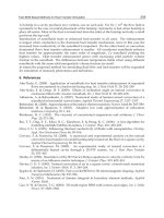
SCPPs consist of a transparent collector which heats the air near the ground and guides it
into the base of a tall chimney coupled with it, as shown in Fig. 1. The relatively lighter air
rises in the chimney promoting a flow allowing electricity generation through turbines at
the base of the chimney. The literature about SCPP is extensively referred by (Bernardes
2010) at that time and there is no means of doing it here.
Fig. 1. Sketch of a SCPP.
Heat Transfer - Mathematical Modelling, Numerical Methods and Information Technology
608
The problem to be addressed here is the flow in the SCPP collector, i.e., the flow between
two finite stationary disks concentrating on radially converging laminar and turbulent flow
development and heat transfer. However, as a typical solar radiation dependent device,
laminar, transient and turbulent and natural, mixed and forced convection, as well, may
take place in the collector. Additionally, due to non uniform solar heating or ground
roughness, the flow in collector should not converge axi-symmetrically. For that reason, the
forced/natural convective flow in the SCPP collector can be treated as a flow:
1. between two independent flat plates in parallel flow or,
2. in a channel between parallel flat plates in parallel flow or
3. between two finite stationary disks in converging developing flow.
Moreover, collector convective heat transfers determine the rate at which thermal energy is
transferred:
• between the roof and the ambient air,
• between the roof and the air inside the collector,
• between the absorber and the collector air.
It is necessary to remember that the literature for some typical heat transfer problems is
extensive but scarce or even inexistent for some boundary conditions like constant heat flux,
or for flow above rough surfaces like the collector ground.
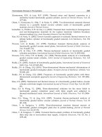
1.1 Influence of the roof design in the heat transfer in collector
An important issue regarding the SCPP collector is its height as function of the radius. Some
studies found in the literature (Bernardes 2004, Bernardes et al. 2003, Schlaich et al. 2005) make
use of a constant height along the collector (Fig. 3). In this case, the air velocity increases
continually due to the cross section decrease towards the chimney reducing the pressure in the
collector, as shown in Fig. 2. Such pressure difference between the collector and surroundings
allied with unavoidable slight gaps in the collector roof can result in fresh air infiltration
reducing the air temperature. Furthermore, velocity variations in the collector denote different
heat flows and, in this case, higher heat transfer coefficients and, consequently, a fresher
collector close to the chimney. Besides, the relatively reduced collecting area in this region
represents also lower heat gains harming the collector performance.
Fig. 2 also illustrates the air velocity for slight slanted roofs, evidencing a kind of ‘bathtub
effect’. Through this effect, the air velocity drops after the entrance region due to the cross
area increasing and, especially for greater angles like 0.1° and 0.5°, remains minimal until
achieves the chimney immediacy. In this region, the air velocity increases exponentially.
Such air velocity profiles in collector represents lower heat transfer coefficients for a great
collector area and, thus, lower heat transfer to the flowing air – predominance of natural
convection – and higher losses to the ambient. Consequently, for this arrangement, the
collector efficient would be inferior. (Bernardes et al. 1999) also disclose the presence of
swirls when the flat collector roof is slanted.
The roof configuration for constant cross area – adopted by (Kröger & Blaine 1999, Pretorius
& Kröger 2006) – leads, obviously, to constant air velocity in collector and, in terms of heat
transfer, is the most appropriate for the collector. However, the roof height can achieve large
values leading to higher material consumption (Fig. 3).
Lastly, the air velocity in the chimney should be taken in account. For a chimney diameter of
120 m, a collector diameter of 5000 m, an entrance collector height of 1 m and an entrance air
velocity of 1 m/s, the air velocity in the chimney is 3 m/s approximately (continuity
Convective Heat Transfer Coefficients for Solar Chimney Power Plant Collectors
609
equation). Consequently, lower collector air velocities at the chimney entry are preferably
and the roof configuration for constant cross area fits relatively well this condition.
Fig. 2. Air velocity in collector for different roof arrangements.
Fig. 3. Roof height for different roof arrangements.
Heat Transfer - Mathematical Modelling, Numerical Methods and Information Technology
610
2. Flow in collector as a flow between two independent flat plates
Due to a reasonable relative distance between the ground surface and the collector roof, the
flow in a SCPP collector can be regarded as a flow involved by two independent plates, as
employed be (Bernardes 2004). In this way, it is necessary to assume that the boundary
layers develop indefinitely and separately.
2.1 Forced convection
The forced convection takes plate in the SCPP collector when the incident radiation is able to
heat up the collector as much as necessary to promote a continuing air flow. In this
condition, higher heat transfer coefficients are expected.
As represented in Fig. 4, the boundary layer flow over a flat plate regarding forced
convection develops from a laminar boundary layer becoming unstable and turbulent after a
certain plate length, when Re
x
= u
∞
·x/ν ≈ 5 × 10
5
. A more detailed description of this flow
can be widely found in the literature, for instance, (Çengel 2007, Incropera 2007, Rohsenow
et al. 1998), etc. In the following, the most important heat transfer coefficients and Nusselt
numbers are introduced and their extent of application discussed.
Fig. 4. Flow development in a flat plate in parallel flow.
Fundamentally, solution methodologies for the governing equations are based on the
nondimensional groups and analytical means can be used to solve only a limited number of
cases. Otherwise, experimental or numerical solution procedures must be employed.
Laminar flow – prescribed temperature
For two-dimensional cases, where the flow is laminar up to the point of transition to
turbulent flow or flow separation, established analytical solutions can be extensively found
in literature.
For the case of the laminar flow over a flat plate at uniform temperature and Pr ≈ 1 (like air,
for instance), the similarity equations approach returns the local Nusselt number showed by
equation ( 1 ) and the average Nusselt number by equation ( 2 ).
12 13
0.332Re Pr
xx
Nu =
(1)
____
12
13
0.664Re Pr
L
Nu = (2)
Convective Heat Transfer Coefficients for Solar Chimney Power Plant Collectors
611
()
16
14
Re Pr
0.25 Pr
1 1.7 Pr 21.36Pr
x
Nu
π
=
≤≤∞
++
(3)
(Baehr & Stephan 1996)
Laminar flow – Uniform wall heat flux
For a flat plate subjected to uniform heat flux instead of uniform temperature, the local and
average Nusselt number are given by equations ( 4 ) and ( 5 ) respectively.
12 13
0.453Re Pr Pr 0.6
xx
Nu => (4)
(Çengel 2007)
____
12
13
0.6795Re Pr
L
Nu = (5)
(Lienhard IV & Lienhard V 2008)
()
16
14
Re Pr
0.25 Pr
2 1 2.09Pr 48.74Pr
x
Nu
π
=
≤≤∞
++
(6)
(Baehr & Stephan 1996)
Turbulent flow – prescribed temperature
For the case of turbulent flows, approximate analytical solutions based on
phenomenological laws of turbulence kinetics are established for local and average Nusselt
numbers as introduced by equations ( 7), ( 8 ) and ( 9 ).
0.8 0.43 5 6
0.032Re Pr 2 10 Re 5 10
xx x
Nu =×<<×
(7)
(Žukauskas & Šlanciauskas 1999)
57
13
0.8
510 Re 10
0.0296Re Pr
0.6 Pr 60
x
xx
Nu
×≤ ≤
=
≤≤
(8)
(Çengel 2007)
57
____
13
0.8
510 Re 10
0.037Re Pr
0.6 Pr 60
L
L
Nu
×≤ ≤
=
≤≤
(9)
(Çengel 2007)
Entire plate
A relation suitable to calculate the average heat transfer coefficient over the entire plate
including laminar and turbulent is given by equation ( 10 ).
()
57
____
13
0.8
510 Re 10
0.037Re 871 Pr
0.6 Pr 60
L
L
Nu
×≤ ≤
=−
≤≤
(10)
(Çengel 2007)
Heat Transfer - Mathematical Modelling, Numerical Methods and Information Technology
612
Turbulent flow – uniform wall heat flux
When the turbulent flow over a flat plate is subjected to uniform heat flux, the local and
average Nusselt numbers are given by equations ( 11 ) ( 12 ) and ( 13 ).
13
0.8
0.0308Re Pr
xx
Nu =
(11)
(Çengel 2007)
____
0.8 0.43 5 7
0.037Re Pr 2 10 Re 3 10
LL
Nu =×≤≤× (12)
(Lienhard IV & Lienhard V 2008)
()
0.8
57
23
0.1
0.037Re Pr
5 10 Re 10 0.6 Pr 2000
1 2.443Re Pr 1
Nu
−
=×<<<<
+−
(13)
(Petukhov & Popov 1963)
Mixed forced convection
22 7
10 Re 10
lam turb
Nu Nu Nu=+ << (14)
(Baehr & Stephan 1996)
2.2 Natural convection
Natural convection at horizontal isothermal plates of various planforms with unrestricted
inflow at the edges are related with the correlations presented by equations ( 15 ), ( 16 ) and
( 17 ).
()
____
3
*
gTL
Ra
β
να
Δ
=
(15)
*
____
qL
Nu
ATk
=
Δ
(16)
*
/LA
p
= (17)
Uniform Heat Flux Parallel Plates
Classical correlations:
(Lloyd & Moran 1974) presented correlations for natural convection at horizontal isothermal
plates taking into account both hot side up or cold side down and hot side down or cold
side up, as shown by equations ( 18), ( 19 ) and ( 20).
14
47
0.54 10 10Nu Ra Ra=≤≤ (18)
hot side up or cold side down, (Lloyd & Moran 1974)
Convective Heat Transfer Coefficients for Solar Chimney Power Plant Collectors
613
13
710
0.15 10 10Nu Ra Ra=<≤
(19)
hot side up or cold side down, (Lloyd & Moran 1974)
13
510
0.27 10 10Nu Ra Ra=<≤ (20)
hot side down or cold side up, (Lloyd & Moran 1974)
(Rohsenow et al. 1998) introduced correlations for heated upward-facing plates with
uniform temperature or heat flux (1 < Ra < 10
10
), namely, equations ( 21 ), ( 22 ), ( 23 ) and
(24).
14
10
0.835 1 10 0.515 for air
ll
Nu C Ra Ra C=<<= (21)
()
1.4
ln 1 1.4 /
lam
Nu
Nu
=
+
(22)
13
0.14 for air
UU
turb t t
Nu C Ra C== (23)
(
)
1
10
m
mm
tlamturb
Nu Nu Nu m=+ =
(24)
On the other hand, for horizontal isothermal heated downward-facing plates, equations
( 25 ) and ( 26 ) are suggested by (Tetsu et al. 1973) for 10
3
< Ra < 10
10
.
()
()
15
310
29
910
0.527
10 10
11.9/Pr
Nu Ra Ra=<<
+
(25)
()
2.5
ln 1 2.5/
lam
Nu
Nu
=
+
(26)
Mixed natural convection
44 4
lam turb
Nu Nu Nu=+ (27)
(Baehr & Stephan 1996)
Free and forced convection including radiative heat flux
The work by (Burger 2004) introduced correlations, which took into account significant
natural convection mechanisms by evaluating convective and radiative heat fluxes onto or
from a smooth horizontal flat plate exposed to the natural environment. As shown in
equation ( 28 ), T
m
is the mean temperature between the collector roof and ambient air, g is
the gravitational constant and ΔT is the difference between the roof and ambient air
temperature. The variables ρ, μ, c
p
and k symbolize the density, dynamic viscosity, specific
heat capacity and thermal conductivity of the air respectively, all of which are evaluated at
the mean temperature T
m
. If the collector roof temperature only marginally exceeds the
ambient temperature equation ( 29 ) can be employed. Equation ( 30 ) was derived by
(Kröger 2004) using Gnielinski’s equation for fully developed turbulent flow, by
approximating the flow in the collector as flow between variably spaced plates.