Waste Water Treatment and Reutilization Part 9 pptx
Bạn đang xem bản rút gọn của tài liệu. Xem và tải ngay bản đầy đủ của tài liệu tại đây (1.45 MB, 30 trang )
Degradation of Nitroaromatic Compounds by Homogeneous AOPs
229
Fig. 6. Linear relationships among functions of z
NBE
slow
and different parameters
+
+
≅
+
2
22
2
ss 2 2
•
Fe
Slow
NBE H O 2 2
k.[Fe].[HO]
[HO ]
k .[NBE] k .[H O ]
(50)
Given that k
Fe+3
<<k
Fe+2
, during the slow phase the Fe
2+
concentration is negligible and
[Fe
3+
]
slow
≈ [Fe
3+
]
0
. By combining the rate equations for NBE and H
2
O
2
with eqns (49) and
(50), the following expressions for the slow phase can be obtained (Nichela et al., 2008)
NBE 3
NBE
Slow 1 2 2
NBE HP 2 2
k.[NBE]
r k.[Fe].[HO]
k[NBE]k[HO]
+
⎧
⎫
⎪
⎪
=
⎨
⎬
+
⎪
⎪
⎩⎭
(51)
HP 3
HP 2 2
Slow 1 2 2
NBE HP 2 2
k.[HO]
r k .[Fe ].[H O ]. 2
k [NBE] k [H O ]
+
⎧
⎫
⎪
⎪
=+
⎨
⎬
+
⎪
⎪
⎩⎭
(52)
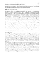
It is worth to mention that eqns (51) and (52) are in excellent agreement with the
experimental trends, as it is observed in Fig. 6.
3.6.3 Semi quantitative analysis of the autocatalytic profiles
We also used Fenton-like process for the oxidation of a series of structurally related
substrates, in order to test the autocatalytic nature of these systems (Nichela et al., 2010). The
model compounds were 2-hydroxybenzoic (2HBA), 2,4-dihydroxybenzoic (24DHBA), 2-
hydroxy-5-nitrobenzoic (2H5NBA), 4- hydroxy-3-nitrobenzoic (4H3NBA) and 2- hydroxy-4-
nitrobenzoic (2H4NBA) acids. The normalized profiles of [S] and [H
2
O
2
] are shown in Fig. 7.
The kinetic behavior is strongly dependent on the nature of the substrate and, excepting
4H3NBA, the substrates clearly display autocatalytic decays, the profiles being like inverted
S-shaped curves. The quantitative description of this kinetic traces is rather complicated
and, to the best of our knowledge, no simple equation has been proposed to model
Waste Water - Treatment and Reutilization
230
Time / min
0 25 50 75 100 125
[S]
/
[S]
0
0.0
0.2
0.4
0.6
0.8
1.0
1.2
2H5NBA
2H4NBA
2HBA
24DHBA
4H3NBA
Time / min
0255075100125
[H
2
O
2
] / [H
2
O
2
]
0
0.0
0.2
0.4
0.6
0.8
1.0
1.2
2H5NBA
2H4NBA
2HBA
24DHBA
4H3NBA
Fig. 7. Normalized concentration profiles of model substrates obtained in dark Fenton-like
process.
concentration profiles of this kind that are frequently found in degradation studies of
environmental relevance. For the quantitative comparison of the kinetic curves we proposed
an empirical equation for fitting the normalized decay profiles (Nichela et al., 2010)
(1 a t d)
fd
1(tb)
c
/
=
−
×−
+
+
(53)
In this equation, the parameters a, b, c and d may be employed to characterize the average
oxidation rate during the slow phase (the normalized initial rate), the time required to reach
half of the initial concentration (the apparent half-life), the average slope during the fast
phase and the final residual value, respectively. The solid lines in Fig. 7 show that eqn (53)
allows a precise estimation of the temporal dependence of concentration profiles. Although
the chemical structures of the substrates are closely related, the degradation timescales are
remarkably different. During early reaction stages, the depletion rates follow the trend
4H3N-BA > 2H4N-BA ≈ 24DH-BA > 2H-BA >> 2H5NBA. It should be noted that, despite
lacking a precise kinetic meaning, eqn (53) has a key advantage from a practical point of
view: it requires only a few experimental points to draw S-shaped curves that closely
describe the complex autocatalytic profiles frequently observed in Fenton-like systems.
3.7 Photo-Fenton systems
The strategy most frequently used in Fenton systems to increase the reaction rates and
improve the mineralization efficiencies is the use of UV and/or visible irradiation. The
enhancement is mostly due to the photolysis of Fe
3+
complexes which dissociate in the
excited state to yield Fe
2+
and an oxidized ligand (Sima and Makanova, 1997)
[Fe
3+
(OH)]
2+
+hν→ Fe
2+
+ HO
•
(54)
[Fe
3+
(RCOO)]
2+
+hν→ Fe
2+
+ CO
2
+ R
•
(55)
Photo-Fenton techniques are useful since even at low [Fe
3+
] high reaction rates are obtained.
Besides, mineralization may be achieved through the photolysis of stable ferric complexes.
3.7.1 Influence of reaction conditions
The photo-Fenton degradation of NBE was studied under different conditions using
simulated solar irradiation (Carlos et al., 2009). The induction period preceding the catalytic
Degradation of Nitroaromatic Compounds by Homogeneous AOPs
231
phase is significantly shortened since the rates of the initial slow phase are enhanced by
irradiation, although the effect of simulated solar light on the rates of the fast phase is
negligible. The enhancement of the slow phase may be explained taking into account the
contribution of photoinduced processes, such as the photoreduction of Fe
3+
in the
predominant Fe
3+
–aquo complex at pH 3 by inner-sphere ligand-to-metal charge transfer
(LMCT) (Lopes et al., 2002). At early stages, rxn (54) provides an alternative Fe
3+
reduction
pathway that is faster than rxn (45), thus substantially increasing Fe
2+
and HO
•
production
rates. By contrast, the rates associated to the fast phase are independent of irradiation since
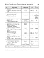
they are mainly governed by thermal reactions (46) and (47). The effect of the initial
concentrations on NBE and H
2
O
2
profiles are shown in Fig. 8.
Time (min.)
0 10203040
[NBE]/[NBE]
0
0.0
0.2
0.4
0.6
0.8
1.0
1.2
[NBE] = 1.0 mM
[NBE] = 0.8 mM
[NBE] = 0.3 mM
Time (min.)
0 10203040
[H
2
O
2
]/[H
2
O
2
]
0
0.0
0.2
0.4
0.6
0.8
1.0
1.2
Time (min.)
0 102030405060
[NBE]/[NBE]
0
0.0
0.2
0.4
0.6
0.8
1.0
1.2
[Fe(III)]
= 0.05 mM
[Fe(III)]
= 0.09 mM
[Fe(III)]
= 0.10 mM
[Fe(III)]
= 0.20 mM
Time (min.)
0 102030405060
[H
2
O
2
]/[H
2
O
2
]
0
0.0
0.2
0.4
0.6
0.8
1.0
1.2
Time (min.)
0 1020304050
[NBE]/[NBE]
0
0.0
0.2
0.4
0.6
0.8
1.0
1.2
[H
2
O
2
] = 2.3 mM
[H
2
O
2
] = 3.5 mM
[H
2
O
2
] = 7.7 mM
Time (min.)
0 1020304050
[H
2
O
2
]/[H
2
O
2
]
0
0.0
0.2
0.4
0.6
0.8
1.0
1.2
Fig. 8. Effect of initial conditions on the concentration profiles obtained during NBE photo-
Fenton treatment.
In line with the results shown in section 3.6.1, the rates of the slow phase increase with [Fe
+3
]
and [H
2
O
2
], whereas z
NBE
slow
values decreases with organic matter loading.
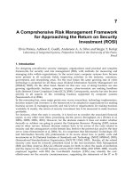
3.7.2 Influence of substrate structure
Degradation of the substrates of section 3.6.3 was studied under identical conditions but
using UV irradiation (Fig. 9) (Nichela et al., 2010). As in the case of NBE, the slow initial
phase is shortened in irradiated systems. The comparison between the different substrates
reveals the same reactivity order as observed for Fenton-like systems. The solid lines in Fig.
9 confirm the utility of eqn (53) for describing autocatalytic profiles.
3.7.3 Photoenhancement factor
With the purpose of making a rough estimation of the relative contribution of photo
stimulated pathways in photo-Fenton systems, we proposed (Nichela et al., 2010) the
parameter photo enhancement factor (PEF) defined by
Waste Water - Treatment and Reutilization
232
Time / min
0 1530456075
[S] / [S]
0
0.0
0.2
0.4
0.6
0.8
1.0
1.2
2H5NBA
2H4NBA
2HBA
24DHBA
4H3NBA
Time / min
0 1530456075
[H
2
O
2
] / [H
2
O
2
]
0
0.0
0.2
0.4
0.6
0.8
1.0
1.2
2H5NBA
2H4NBA
2HBA
24DHBA
4H3NBA
Fig. 9. Normalized concentration profiles of model substrates obtained in the photo-Fenton
process.
Phot Dark
App App
Phot
App
kk
PEF
k
−
= (56)
where k
Dark
App
and k
Phot
App
are the rate constants linked to the dark and photo enhanced
reactions, respectively. The PEF is a useful index that allows evaluating the contribution of
photo induced processes in photo-Fenton systems. In addition, the “apparent half-lives” can
be used to define an “overall photo enhancement factor” (PEF
O
) by the following relation
Phot
1/2
O
Dark
1/2
t
PEF 1
t
=−
(57)
The analysis of PEF
O
values corresponding to the normalized profiles showed that higher
photo enhancements are found for conditions where the dark reaction is slower. This
behavior may be interpreted assuming that the rates of the photo induced reactions mostly
depend on the photon flux and do not significantly depend on the nature of the substrate or
the reaction conditions. Therefore, for a relatively constant photochemical contribution, the
slower the dark reaction is, the greater the effect of photoinduced pathways results.
4. Product yields and mechanism of nitrobenzene transformation
Nitrobenzene thermal degradation was investigated using Fenton´s reagent in several
experimental conditions. This section deals with the analysis of the distributions of
intermediate reaction products and the mechanisms of nitrobenzene decomposition.
4.1 Initial steps of NBE transformation
From the analysis of reaction products distributions as a function of NBE conversion degree,
a mechanism was proposed for NBE degradation in AOP systems (Carlos et al., 2008). The
first steps involve two main pathways: hydroxylation pathways which yield phenolic
derivatives and the nitration pathway which yields 1,3-dinitrobenzene (scheme 1).
Hydroxyl radicals usually react with benzene derivatives by electrophilic addition to form
hydroxycyclohexadienyl-like radicals (Walling, 1975; Oturan and Pinson, 1995) that can
undergo different processes according to the reaction conditions (i.e. [Fe
2+
], [H
2
O
2
], [Fe
3+
],
Degradation of Nitroaromatic Compounds by Homogeneous AOPs
233
NO
2
NO
2
OH
NO
2
OH
NO
2
OH
OH
NO
2
NO
2
Scheme 1. Nitrobenzene primary hydroxylation and nitration pathways
[O
2
], etc.) (Pignatello et al., 2006). Since HO
•
reacts with both the target substrate and its
reaction products, the concentration profiles of reaction intermediates during AOP
treatments result from a balance between their formation and degradation rates. As the
composition of the reaction mixture changes with time, both the formation yields and
degradation rates of intermediate products can vary during the course of reaction.
Therefore, an important feature to be considered is the dependence of the mechanism with
reagent concentrations since these parameters may influence the kinetics as well as the
distribution of products thereby affecting the global efficiency of the detoxification process.
4.2 Analysis of primary product yields
The equations derived in section 2.3 were used to analyze the influence of reaction
conditions on the primary reaction yields. The results are given below.
4.3 Hydroxylation Pathways
Normalized yields obtained in Fenton systems reveal significant differences in the product
distributions associated to each reaction stage (Carlos et al., 2008). The η
N
ONP
values
observed during the initial fast phase are at least 30% lower than those determined in the
slow one. On the contrary, η
N
phenol
values are higher in the fast phase than in the slow one.
In addition, increasing [Fe
2+
]
0
markedly decreases η
N
ONP
while significantly increases
η
N
phenol
values.
The observed differences in the normalized yields may be explained taking into account that
the first oxidation step is the HO
•
radical addition on the aromatic ring to form
hydroxycyclohexadienyl-type radicals.
.
NO
2
OH
NO
2
.
OH
+
(58)
This type of radicals can undergo different reactions such as dimerization,
disproportionation, oxygen addition to give corresponding peroxy-radical or can participate
in electron transfer reactions with transition metals depending on the substituents in the
aromatic ring and on the medium nature (Chen and Pignatello, 1997). The addition of HO
•
radical in ortho, meta and para positions of the nitrobenzene ring can yield 2-nitrophenol
(ONP), 3-nitrophenol (MNP) and 4-nitrophenol (PNP) by oxidation or disproportionation of
the corresponding HNCHD
•
radicals (Bathia, 1975)
Waste Water - Treatment and Reutilization
234
.
NO
2
NO
2
OH
OH
Oxid.
o, m, p - isomers
(59)
NO
2
.
NO
2
NO
2
OH
OH
H
2
O
o, m, p - isomers
2
+
+
Dispr.
(60)
Usually, the distribution of isomers in HO
•
mediated hydroxylation does not obey the
foreseen orientation according to deactivating characteristics of the nitro group but it
depends significantly on reaction conditions.
4.3.1 Effect of O
2
In the presence of oxygen the second-order reactions have a secondary contribution to the
primary phenolic yields, since HNCHD
•
radicals rapidly decay following a pseudo first
order kinetics by addition of O
2
. The oxidation of HNCHD
•
radicals by O
2
is a very complex
process and several pathways leading to different reaction products can compete (Pan et al.,
1993). Among the reaction routes involving the peroxyl radicals formed by O
2
addition to
HNCHD
•
, the elimination of HO
2
•
yields the corresponding nitrophenols. Hence, [O
2
] plays
an important role in NBE degradation pathways. In the absence of O
2
, bimolecular processes
become significant. Our results suggest that in crossed disproportionation reactions, meta-
HNCHD
•
radicals may act as oxidizers with respect to para-HNCHD
•
or ortho-HNCHD
•
radicals, yielding PNP or ONP and NBE (rxn (60)).
4.3.2 Effect of Fe
2+
The low ONP yields obtained with high [Fe
2+
] can be explained by considering two
consecutive processes, i.e. the selective reduction of ortho-HNCHD
•
radicals by Fe
2+
to give
Fe
3+
and the corresponding organic anion followed by the regeneration of the starting
nitrobenzene
Fe
2+
+
•
OHC
6
H
5
NO
2
→ C
6
H
5
NO
2
+ Fe
3+
+ OH
-
(61)
4.3.3 Effect of Fe
3+
The tests carried out in air saturated solutions show an increase of η
N
ONP
with the [Fe
3+
].
Since it is well known that Fe
+3
is not a strong oxidant in aromatic hydroxylation (Fang et
al., 1996), the increase of ONP yield with [Fe
3+
]
0
can be explained if it is assumed that ortho-
HNCHD
•
radicals are stabilized by means of Fe
3+
complexation through one of the oxygen
atoms belonging to the nitro group and the oxygen of the HO group. Within this context, the
relatively high stability of ortho-NHCHD
•
radicals complexed with Fe
3+
ions would allow
explaining the observed results.
4.3.4 Phenol production
The presence of traces of phenol and NO
2
-
among the initial reaction products shows that a
small fraction of HO
●
radicals attacks the nitrobenzene ipso position and induces the
Degradation of Nitroaromatic Compounds by Homogeneous AOPs
235
cleavage of the nitro group. The experimental results showed that the increase of [Fe
2+
] is
accompanied by an increase of phenol yiled. Therefore, phenol may be formed from
nitrobenzene through rxn (62)
NO
2
OH
O
2
N
H
OH
.
.
(-HNO
2
)
O
H
.
O
.
Fe
2+
OH
+
(62)
4.4 Nitration Pathways
As NBE degradation proceeds in AOP systems, the organic nitrogen is mainly released as
nitrite ions (García Einschlag et al., 2002b; Carlos et al., 2008; Carlos et al., 2009). In the
darkness and at pH 3, the released HNO
2
/NO
2
-
(pKa = 3.3) can lead to the formation of
different nitrating agents such as peroxynitrous acid (ONOOH) and the
•
NO
2
radical
through the following reactions (Fischer and Warneck, 1996; Merenyi et al., 2003):
HNO
2
+ H
2
O
2
+ H
+
→ ONOOH + H
2
O + H
+
k
HOONO
(63)
HNO
2
/NO
2
-
+
•
OH →
•
NO
2
+ H
2
O/HO
•
k
NO2-
(64)
The ONOOH decomposes in acid media yielding NO
3
-/
H
+
and
•
NO
2
/ HO
•
. Therefore,
•
NO
2
radicals can be in situ formed by NO
2
-
oxidation trough either thermal or photochemical
reactions. On the other hand, in UV/I systems both HNO
2
/NO
2
-
and NO
3
-
photolysis may
also contribute to the production of reactive nitrogen species through the photolytic
reactions (34), (35), (36) and (38) (Mack and Bolton, 1999; Goldstein and Rabani, 2007).
•
NO
2
and ONOOH are nitrating agents capable of participating in the formation of 1,3-DNB
under the reaction conditions used in the different AOPs.
In this section we analyze the conditions that favor the formation of 1,3-DNB during NBE
treatment using different AOPs (Carlos et al., 2010). Fig. 10 plots the amount of 1,3-DNB
formed (expressed as [1,3-DNB]/[NBE]
0
) against the conversion degree of nitrobenzene
(defined by 1-[NB]/[NBE]
0
). In all cases, the production of 1,3-DNB is practically negligible
for NBE degradation percentages lower than 20%. Subsequently, the formation of 1,3-DNB
increases until reaching a maximum for conversion degrees of about 0.9. Finally, as NBE is
completely consumed, a steady decrease in 1,3-DNB concentration is observed. The latter
trend is consistent with the hypothesis that 1,3-DNB is a primary product of NBE
degradation (Carlos et al., 2008). It is important to note that, although curves in Fig. 10 show
similar trends of 1,3-DNB formation, UV/H
2
O
2
process yielded much lower 1,3-DNB levels
than Fenton systems, thus suggesting an important contribution of iron species in NBE
nitration pathways.
4.4.1 Influence of HNO
2
/NO
2
-
and NO
3
-
in dark processes
NBE degradation experiments using Fenton’s reagent in the dark and with different initial
concentrations of NO
2
-
or NO
3
-
show that the presence of NO
3
-
does not affect the
consumption of NBE nor the production of 1,3-DNB while the presence of NO
2
-
decreases
NBE consumption and significantly increases the fraction of NBE transformed to 1,3-DNB.
The latter trends can be explained by considering the enhancement, through rxn (64) of both
HO
•
radical scavenging and
•
NO
2
production as [NO
2
-
]
0
is increased. Taking into account
Waste Water - Treatment and Reutilization
236
Fig. 10. Relative production of 1,3-dinitrobenzene against the conversion degree of
nitrobenzene.
these results, the feasibility of a direct reaction between NBE and
•
NO
2
was tested by
incubating NBE in solutions of HNO
2
at acid pH. In the latter conditions HNO
2
decomposes
yielding
•
NO
2
,
•
NO and H
2
O (Vione et al., 2005). Since [NBE] remained constant and no
formation of 1,3-DNB was observed the direct reactions of either
•
NO
2
or
•
NO with NBE
were neglected.
4.4.2 Influence of HNO
2
/NO
2
-
and NO
3
-
in photochemical processes
NBE degradation experiments were conducted at pH 3 in both UV/HNO
2
/NO
2
-
and
UV/NO
3
-
systems using different additive concentrations (García Einschlag et al., 2009). In
UV/HNO
2
/NO
2
-
systems DNB yield (η
0
1,3-DNB
) was negligible below 1mM of [NO
2
-
]
0
, then
increased up to a value of 0.06 and remained constant above 8mM of [NO
2
-
]
0
. On the other
hand, in UV/NO
3
-
systems significant amounts of 1,3-DNB were observed even for very low
[NO
3
-
] and η
0
1,3-DNB
increased with [NO
3
-
], 1,3-DNB being the most important by-product at
high NO
3
-
concentrations.
4.4.3 Influence of Fe
3+
and O
2
in UV/HNO
2
/NO
2
-
and UV/NO
3
-
systems
An enhancement of 1,3-DNB formation upon Fe
3+
addition was observed in
UV/HNO
2
/NO
2
-
systems. The increase of 1,3- DNB production with increasing [Fe
3+
]
0
in
UV/HNO
2
/NO
2
-
systems was explained by considering the production of
•
NO
2
through
the sequence of reactions (54) and (64). In contrast, the presence of Fe
3+
in UV/NO
3
-
systems significantly increased NBE consumption rate while strongly decreased η
0
1,3-DNB
.
The latter result may be explained by taking into account: (i) an enhanced contribution of
NBE oxidation pathways since higher production rates of nitrophenol isomers were
observed, and (ii) the decrease of the relative importance of reactions (36) and (38) due to
the lower fraction of photons absorbed by NO
3
-
. In addition, UV/NO
3
-
systems in the
absence of O
2
showed η
0
1,3-DNB
values higher than those obtained under oxygenated
conditions.
4.4.4 Nitration mechanism of NBE under mild AOP conditions
The set of results presented in section 4.4 is consistent with a nitration pathway involving a
HO
•
+
•
NO
2
mechanism. In the experimental domain tested, the prevailing NBE nitration
pathway is most probably the reaction between the
•
OH-NB adduct and
•
NO
2
radicals (rxn
65A).
Degradation of Nitroaromatic Compounds by Homogeneous AOPs
237
(65)
5. Conclusions
It is well known that rather complex reaction manifolds with many reaction steps are
involved in the degradation of aromatic pollutants. However, results obtained in
degradation experiments of nitroaromatic compounds using different homogeneous AOPs
can be analyzed by using simplified models that take into account only a reduced number of
kinetically key steps. These models are capable of correctly describing the main kinetic
features of the studied systems by using only a few parameters as predictive tools. This kind
of approach has important implications from a practical-technological viewpoint since it
may be used for the rational design of efficient processes.
6. Acknowledgements
This work was partially supported by the project X559 of UNLP (Argentina). Daniela
Nichela thanks the CONICET for a grant supporting her Ph.D. thesis. Luciano Carlos and
Fernando García Einschlag are members of CONICET. The authors want to thank to the
research groups of Prof. André M. Braun (University of Karlsruhe), Prof. Edmondo
Pramauro (University of Turin) and Prof. Esther Oliveros (University Paul Sabatier of
Toulouse) for the kind collaborations. Fernando García Einschlag is especially grateful for
the support received from Prof. Dr. André M. Braun and Prof. Dr. Esther Oliveros
throughout his research career.
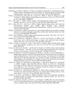
7. References
Bathia, K., 1975. Hydroxyl radical induced oxidation of nitrobenzene. Journal of Physical
Chemistry 79, 1032-1038.
Braun, A.M., Maurette, M.T., Oliveros, E., 1986. Photochemical Technologies. J. Willey &
Sons., New York.
Buxton, G.V., Greenstock, C.L., Helman, W.P., Ross, A.B., 1988. Critical review of rate
constants for reactions of hydrated electrons, hydrogen atoms and hydroxyl
radicals in aqueous solution. J. Phys. Chem. Ref. Data 17, 513-886.
Carlos, L., Fabbri, D., Capparelli, A.L., Bianco Prevot, A., Pramauro, E., Garc
ía Einschlag, F.,
2009. Effect of simulated solar light on the autocatalytic degradation of
nitrobenzene using Fe3+ and hydrogen peroxide. Journal of Photochemistry and
Photobiology A: Chemistry 201, 32-38.
Waste Water - Treatment and Reutilization
238
Carlos, L., Fabbri, D., Capparelli, A.L., Prevot, A.B., Pramauro, E., Einschlag, F.S.G., 2008.
Intermediate distributions and primary yields of phenolic products in nitrobenzene
degradation by Fenton's reagent. Chemosphere 72, 952-958.
Carlos, L., Nichela, D., Triszcz, J.M., Felice, J.I., García Einschlag, F.S., 2010. Nitration of
nitrobenzene in Fenton's processes. Chemosphere 80, 340-345.
Crittenden, J.C., Hu, S., Hand, D.W., Green, S.A., 1999. A kinetic model for H2O2/UV
process in a completely mixed batch reactor. Water Research 33, 2315-2328.
Chan, K.H., Chu, W., 2003. Modeling the reaction kinetics of Fenton’s process on the
removal of atrazine. Chemosphere 51, 305-311.
Chen, R., Pignatello, J.J., 1997. Role of quinone intermediates as electron shuttles in fenton
and photoassisted fenton oxidations of aromatic compounds. Environmental
Science and Technology 31, 2399-2406.
De Laat, J., Gallard, H., 1999. Catalytic decomposition of hydrogen peroxide by Fe(III) in
homogeneous aqueous solution: Mechanism and kinetic modeling. Environmental
Science and Technology 33, 2726–2732.
Fang, X., Mark, G., Sonntag, C.v., 1996. OH· radical formation by ultrasound in aqueous
solutions Part I: The chemistry underlined the terephtalate dosimeter Ultrason.
Sonochem. 3, 57-63.
Fischer, M., Warneck, P., 1996. Photodecomposition of nitrite and undissociated nitrous acid
in aqueous solution. Journal of Physical Chemistry 100, 18749-18756.
García Einschlag, F.S., Carlos, L., Capparelli, A.L., 2003. Competition kinetics using the
UV/H2O2 process: A structure reactivity correlation for the rate constants of
hydroxyl radicals toward nitroaromatic compounds. Chemosphere 53, 1-7.
García Einschlag, F.S., Carlos, L., Capparelli, A.L., Braun, A.M., Oliveros, E., 2002a.
Degradation of nitroaromatic compounds by the UV-H2O2 process using
polychromatic radiation sources. Photochemical and Photobiological Sciences 1,
520-525.
García Einschlag, F.S., Felice, J.I., Triszcz, J.M., 2009. Kinetics of nitrobenzene and 4-
nitrophenol degradation by UV irradiation in the presence of nitrate and nitrite
ions. Photochemical and Photobiological Sciences 8, 953-960.
García Einschlag, F.S., Lopez, J., Carlos, L., Capparelli, A.L., Braun, A.M., Oliveros, E., 2002b.
Evaluation of the efficiency of photodegradation of nitroaromatics applying the
UV/H2O2 technique. Environmental Science and Technology 36, 3936-3944.
Getoff, N., 1997. Peroxyl radicals in the treatment of waste solutions. Peroxyl Radicals, 483-
506.
Glaze, W.H., Lay, Y., Kang, J.W., 1995. Advanced oxidation processes. A kinetic model for
the oxidation of 1,2-dibromo-3-chloropropane in water by the combination of
hydrogen peroxide and UV radiation. Industrial and Engineering Chemistry
Research 34, 2314-2323.
Goldstein, S., Lind, J., Merenyi, G., 2005. Chemistry of peroxynitrites as compared to
peroxynitrates. Chemical Reviews 105, 2457-2470.
Goldstein, S., Rabani, J., 2007. Mechanism of nitrite formation by nitrate photolysis in
aqueous solutions: The role of peroxynitrite, nitrogen dioxide, and hydroxyl
radical. Journal of the American Chemical Society 129, 10597-10601.
Degradation of Nitroaromatic Compounds by Homogeneous AOPs
239
Heit, G., Neuner, A., Saugy, P Y., Braun, A.M., 1998. Vacuum-UV (172 nm) Actinometry.
The Quantum Yield of the Photolysis of Water. Journal of Photochemistry and
Photobiology A: Chemistry 102, 5551-5561.
Lipczynska-Kochany, E., Bolton, J.R., 1991. Flash photolysis/HPLC method for studying the
sequence of photochemical reactions: applications to 4-chlorophenol in aerated
aqueous solution. Journal of Photochemistry and Photobiology, A: Chemistry 58,
315-322.
Lopes, L., De Laat, J., Legube, B., 2002. Charge transfer of iron(III) monomeric and
oligomeric aqua hydroxo complexes: Semiempirical investigation into
photoactivity. Inorganic Chemistry 41, 2505-2517.
Lopez, J.L., García Einschlag, F.S., González, M.C., Capparelli, A.L., Oliveros, E., Hashem,
T.M., Braun, A.M., 2000. Hydroxyl radical initiated photodegradation of 4-chloro-
3,5-dinitrobenzoic acid in aqueous solution. Journal of Photochemistry and
Photobiology A: Chemistry 137, 177-184.
Mack, J., Bolton, J.R., 1999. Photochemistry of nitrite and nitrate in aqueous solution: A
review. Journal of Photochemistry and Photobiology A: Chemistry 128, 1-13.
Mark, G., Korth, H.G., Schuchmann, H.P., Von Sonntag, C., 1996. The photochemistry of
aqueous nitrate ion revisited. Journal of Photochemistry and Photobiology A:
Chemistry 101, 89-103.
Merenyi, G., Lind, J., Czapski, G., Goldstein, S., 2003. Direct determination of the Gibbs'
energy of formation of peroxynitrous acid. Inorganic Chemistry 42, 3796-3800.
Nadezhdin, A., Dunford, H.B., 1979. Oxidation of nicotinamide adenine dinucleotide by
hydroperoxyl radical. A flash photolysis study. Journal of Physical Chemistry 83,
1957-1961.
Nichela, D., Carlos, L., Einschlag, F.G., 2008. Autocatalytic oxidation of nitrobenzene using
hydrogen peroxide and Fe(III). Applied Catalysis B: Environmental 82, 11-18.
Nichela, D., Haddou, M., Benoit-Marquiè, F., Maurette, M.T., Oliveros, E., García Einschlag,
F.S., 2010. Degradation kinetics of hydroxy and hydroxynitro derivatives of benzoic
acid by fenton-like and photo-fenton techniques: A comparative study. Applied
Catalysis B: Environmental 98, 171-179.
Oturan, M.A., Pinson, J., 1995. Hydroxylation by electrochemically generated OH· radicals.
Mono- and polyhydroxylation of benzoic acid: Products and isomers' distribution.
Journal of Physical Chemistry 99, 13948-13954.
Pan, X., Schuchmann, M.N., von Sonntag, C., 1993. Oxidation of benzene by the OH radical.
A product and pulse radiolysis study in oxygenated aqueous solution. Journal of
the Chemical Society, Perkin Transactions 2 3, 289-297.
Pignatello, J.J., Liu, D., Huston, P., 1999. Evidence for an additional oxidant in the
photoassisted Fenton reaction. Environmental Science and Technology 33, 1832-
1839.
Pignatello, J.J., Oliveros, E., MacKay, A., 2006. Advanced oxidation processes for organic
contaminant destruction based on the fenton reaction and related chemistry.
Critical Reviews in Environmental Science and Technology 36, 1-84.
Sima, J., Makanova, J., 1997. Photochemistry of iron (III) complexes. Coordination Chemistry
Reviews 160, 161-189.
Simic, M., 1975. The chemistry of peroxy radicals and its implication to radiation biology.
Fast Processes in Radiation Chemistry and Biology, 162-179.
Waste Water - Treatment and Reutilization
240
Stefan, M.I., Bolton, J.R., 1998. Mechanism of the degradation of 1,4-dioxane in dilute
aqueous solution using the UV/hydrogen peroxide process. Environmental Science
and Technology 32, 1588-1595.
Stefan, M.I., Hoy, A.R., Bolton, J.R., 1996. Kinetics and mechanism of the degradation and
mineralization of acetone in dilute aqueous solution sensitized by the UV
photolysis of hydrogen peroxide. Environmental Science and Technology 30, 2382-
2390.
Stefan, M.I., Mack, J., Bolton, J.R., 2000. Degradation pathways during the treatment of
methyl tert-butyl ether by the UV/H2O2 process. Environmental Science and
Technology 34, 650-658.
Vione, D., Maurino, V., Minero, C., Lucchiari, M., Pelizzetti, E., 2004. Nitration and
hydroxylation of benzene in the presence of nitrite/nitrous acid in aqueous
solution. Chemosphere 56, 1049-1059.
Vione, D., Maurino, V., Minero, C., Pelizzetti, E., 2005. Nitration and photonitration of
naphthalene in aqueous systems. Environmental Science and Technology 39, 1101-
1110.
Walling, C., 1975. Fenton's reagent revisited. Accounts of Chemical Research 8, 125-131.
12
Ferrate(VI) in the Treatment of Wastewaters:
A New Generation Green Chemical
Diwakar Tiwari
1
and Seung-Mok Lee
2
1
Department of Chemistry, School of Physical Sciences, Mizoram University,
2
Department of Environmental Engineering, Kwandong University,
1
India
2
Korea
1. Introduction
Fresh water resources are under tremendous stress throughout the globe. Many areas all
along the developing or even developed nations indicated, the fresh waters are greatly
contaminated by the discharge of untreated sewage/industrial effluents and even variety of
toxins entering naturally. Environmental regulations and public health concerns stated that
wastewaters collected from municipalities and communities supposed to be treated as to
meet the standards given prior its discharge/disposal into the aquatic environment. An
advanced primary treatments aiming to enhanced the removal of colloidal particles and
organic constituents from wastewaters, known to be an essential primary step and a starting
point leading to fewer remaining particles and organic/inorganic contaminants, which in
turn favorable for subsequent biological or physico-chemical treatment process. It is
observed that the coagulation and oxidation/disinfection are two important unit processes
for water treatments. Coagulation destabilizes colloidal impurities and transferred small
particles into large aggregates and facilitates the several dissolved contaminants to adsorb
onto the surface of these aggregates, which can then be removed by sedimentation and
filtration. Disinfection is design to introduce the chemical dose enabled to kill the harmful
organisms’ viz., bacteria, pathogens and viruses etc. from the wastewaters. Additionally, the
usual method of sewage/municipal or even several industrial waste effluents treatment
processes contained with large amount of sludge having various organic and inorganic
compounds occurred, pose serious safely and quality aspects related to environmental
concerns. Further, the final dewatered sludge (often called biosolids), which is to be land
applied, endocrine disruptors and odors of the solids as well as pathogens have been
brought under the serious attention towards its impact of the biosphere. However, such
biosolids once treated carefully, may serve as an economic values as a soil conditioners and
fertilizers etc. Further, the usual sludge handling processes viz., thickening, drying,
digestion and lime stabilization contribute to the on-site odors, became a severe
environmental burden. Different types of organic sulfides and amines are produced in
wastewater treatment facilities to give unpleasant odors. These processes are not effective in
destroying toxic components of sludge viz., endocrine disruptors and potential pathogens.
Waste Water - Treatment and Reutilization
242
Complaints of illness related to the land application of biosolids are found to be increased at
several places.
Similarly, the increased level of pharmaceuticals caused for enhanced level of its occurrence
into the aquatic environment. Studies implied that the pharmaceuticals in surface waters
and their existence in the environment may result in ecotoxicological effects. Ozonation and
filtration with granular activated carbon or even advanced oxidation process (AOP) are
commonly known technological implications for its removal or oxidation. In a line the heavy
burden of surfactants are not directly toxic, but they inhibit both settling of floating particles
and dissolution of atmospheric oxygen into natural waters. The biodegradation of several
surfactants are seemingly slow in the wastewaters treatment plants.
The wastewaters treatment processes included in general the screening/skimming, followed
by the biological/chemical treatment. Further, the advanced treatment methods composed
with disinfections. Hence, the treatment process possessed with several steps comprising of
variety of potentially needed chemicals. It is noteworthy to mention that sometimes the
chemicals used, caused for release/discharge of harmful/toxic chemicals, and ultimately
made additional burden to the environment. The applications of these chemicals restricted
or even banned for its use in the environmental remediation particularly in the treatment of
waste waters. Therefore, the use of conventional treatment methods required to be modified
with adequate selectivity/suitability possessed with optimum efficiency but composed with
more environments friendly. In a line the role of ferrate(VI) seems to be one of possible
alternatives to be used for such treatment methods. The interesting chemistry of ferrates
intended it to various possible applications in diverse area of research. However, its
application in wastewaters treatment is known to be promising way of treatment showed
several interesting observations. Recently, Sharma [1] has reviewed the extrinsic properties
of ferrate in solution along with mechanistic and kinetic evaluation of the use of ferrate
towards several inorganic pollutants.
1.1 Ferrate(VI)
Iron is one of very common element present in nature mainly as elemental iron Fe(0) along
with the ferrous (Fe(II)) and ferric (Fe(III)) ions. The minerals of ferrous and ferric oxides
further include the wuestite, hematite, magnetite, goethite, akagameite etc. (Table 1).
Further, the iron and iron oxide based materials showed immense applications in different
area. Some of the possible applications are magnetic pigments in recording, catalysis and
magnetic fluids etc. Amorphous iron oxides potentially applied in industrial and water
purification technologies. The photocatalytic processes includes the amorphous iron-oxide
as an electrode, transforms water into hydrogen peroxide which further available for
effective degradation of degradable impurities. Recent years, iron/iron oxides in the form of
nano-particles showed unique properties for many advanced technological applications.
Nano-particles of iron and iron-oxides in combination of oxygen and hydrogen peroxides
are capable of oxidizing recalcitrant compounds. Salts of hypoferrite and ferrite as reported
in Table 1 synthesized because of their use as magnetic materials in the modern electronic
industry viz., microwave devices, memory cores of compounds, radar and satellite
communications and usage as permanent magnets.
In addition to three stable oxidation states of iron i.e., 0, +2 and +3, the strong oxidizing
environment caused for the occurrence of higher oxidation states of iron viz.,+4, +5, +6, +8
etc. These higher oxidation states of iron are commonly known as ferrates. Among these
Ferrate(VI) in the Treatment of Wastewaters: A New Generation Green Chemical
243
ferrates the +6 state is relatively stable and easy to synthesize hence, during last couple of
decades greater interest and several research studies conducted using the +6 state of iron.
Additionally, some in situ studies conducted with +4 and +5 oxidation state of iron. The
reactivity of +5 and +4 oxidation state of iron is relatively high comparing to the +6 state.
Ferrate(VI) which was first observed by Stahl in 1902 when he conducted an experiment
detonating a mixture of saltpeter and iron filings, and dissolved the molten residue in water.
This colored solution was subsequently identified as potassium ferrate(VI) (K
2
FeO
4
).
Eckenber and Becquerel in 1834 detected the same color when they heated red mixtures of
potash (potassium hydroxide) and iron ores. Similarly, in 1840, Fremy hypothesized this
colour to be an iron species with high valence, but its formula was suggested FeO
3
[2].
Moreover, because of its stability and cumbersome of its synthesis, it was not used and
studied further. However, some 100 years before systematic studies on ferrates started and
explored the various applications of these compounds.
Compound Name Mineral/Salt
FeO Ferrous oxide Wuestite
Fe
2
O
3
Ferric Oxide Hematite
Fe
3
O
4
Ferrosoferric oxide Magnetite
Fe
2
O
3
.H
2
O Ferric oxide monohydrate Goethite
FeOOH Ferric oxyhydroxide Akaganeite
FeO
2
2-
Hypoferrite Na
2
FeO
2
FeO
2-
Ferrite NaFeO
2
, KFeO
2
FeO
3
2-
Ferrate(IV) Na
2
FeO
3
FeO
4
4-
Ferrate(IV) Na
4
FeO
4
FeO
4
3-
Ferrate(V) K
3
FeO
4
FeO
4
2-
Ferrate(VI) Na
2
FeO
4
, K
2
FeO
4
FeO
5
2-
Ferrate(VIII) Na
2
FeO
5
Table 1. Iron oxide compounds at different oxidation sates of iron
1.2 Preparation of Ferrate(VI)
Three different preparation methods are known for Fe(VI) preparation in laboratory. These
are:
i. Dry oxidation of iron at high temperature
ii. An electro-chemical method
iii. Wet oxidation of iron(III) using chemical oxidizing agents
Briefly these methods are described here:
i. Dry oxidation of iron at high temperature
Initially the ferrate(VI) was obtained by heating the iron filings with nitrates or the mixture
of iron oxides with alkali and nitrates at temperatures of red heat. The final mixtures
includes the ferrate(VI) salts, by-products and remaining reactants. Later, very
systematically several metal salts of Fe(VI) obtained which are described briefly:
Sodium ferrate(VI) was obtained by taking Fe
2
O
3
-NaOH-Na
2
O
2
-O
2
at different
temperatures. Moreover, the fusion of Na
2
O
2
with Fe
2
O
3
at a molar ratio under dry oxygen
conditions at high temperature, yields sodium ferrate(VI). Ferrate(VI) yield which depends
on the initial reagent molar ratio and temperature conditions. The entire process to be
Waste Water - Treatment and Reutilization
244
conducted in a dry glove box and in presence of diphosphorouspentaoxide (P
2
O
5
) and using
high purity iron oxide (99.9 mol %). This was heated prior to use in dry oxygen at 150-200
0
C
as to remove sorbed water. This dried iron oxide was mixed with alkali metal peroxides and
placed in a silver crucible for further thermal treatment. The 100% yield of the ferrate(VI) as
in the form of Na
4
FeO
5
was obtained at the molar ratio of Na:Fe = 4:1 at the exposition
temperature of 370
0
C for more than 12 hours.
Similarly, Fe(VI) was prepared using the galvanizing wastes as the wastes were mixed with
ferric oxide in a muffle furnace at 800
0
C for a while and the sample was cooled and stirred
with solid sodiumperioxide and heated gradually for few minutes. The mixtures were
melted and then cooled resulting with the formation of sodium ferrate(VI):
Fe
2
O
3
+ 3Na
2
O
2
→ 2 Na
2
FeO
4
+ Na
2
O (1)
On the other hand potassium and cesium ferrate(VI) was prepared reacting with the
superoxides of potassium and cesium with iron oxide powder at elevated temperatures of
about 200
0
C and the exposition time of Ca 10 hours.
It can also be prepared at room temperature by mixing iron(II) or iron(III) salt with an
oxidizing chlorine-containing agent in a strong base such as potash or soda. The ferrate(VI)
thus obtained show the formula M(Fe,X)O
4
, where M denotes to two atoms of Na or K or
one atom of Ca or Ba, and X corresponds to atoms whose cation has the electronic structures
of a rare gas.
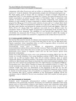
ii. An electro-chemical method
Ferrate was first prepared electrochemically in 1841 by anodic oxidation of iron electrode in
strongly alkaline solution [3]. The basic principle of ferrate production by electrochemical
method is the dissolution of iron anode in the electrolysis process having a strongly alkaline
electrolyte solution. Hence, the preparation of ferrate consists of a sacrificial iron anode in
an electrolysis cell containing a strongly alkaline solution of NaOH or KOH having electric
current serving to oxidize the dissolved iron to Fe(VI) (Fig. 1). The possible anodic and
cathodic reactions involved are;
Anode Reaction: Fe + 8OH
-
→ FeO
4
2-
+ 4H
2
O + 6e
-
(2)
Cathode Reaction: 6H
2
O + 6e
-
→ 3H
2
+ 6OH
-
(3)
Overall reaction Fe + 2OH
-
+ H
2
O → FeO
4
2-
+ 3H
2
(4)
And FeO
4
2-
+ 2K
+
→ K
2
FeO
4
(5)
Different mechanism are proposed for the formation of ferrate(VI). Christian [5] assumed
that the reduction proceeds stepwise first to Fe(III), then to Fe(II) and finally to Fe(0).
However, the three steps mechanism based on intermediate formation are proposed as [6]:
a) The formation of intermediate species
b) The formation of ferrate and the passivation of the electrode
c) The formation of passivating layer that prevents further ferrate generation
The electrochemical production of Ferrate(VI) gives high purity of the product and the
anodic polarizarion of iron electrode in the molten hydroxides is more adequate as
compared to the classical electrolysis in water since water decomposes ferrate(VI) and
passivation greatly reduced in this environment. The current yield during electrochemical
Ferrate(VI) in the Treatment of Wastewaters: A New Generation Green Chemical
245
production increased with the carbon content in the iron anode material used; current yields
were 15% for raw iron, 27% for steel and 50% for cast iron at a current density of 10 Am
-2
with the NaOH concentration of 16.5 mol/L. Moreover, a current efficiency greater than
70% was achieved in preparing the ferrate when silver steel with carbon content of 0.09%
was used. However, with the same conditions, the current efficiency was reduced to 12%
when an alloy with a carbon content of 0.08% was used [7,8].
Fig. 1. Eletrochemical cell used for Ferrate synthesis [4].
Bouzek optimized the optimum conditions for ferrate production particularly the anodic
iron behavior in respect to the anode composition and the influence of the anode material
used in highly concentrated NaOH solutions [9]. Previously, the sinusoidal alternating
current was used to synthesize the ferrate electrochemically [10-12]. The electrodes used
were 99.95 % pure of iron with 14 mol/L NaOH solution as electrolytes and the temperature
was kept between 30 and 60
0
C. These results revealed that the maximum current efficiency
for generating the ferrate was 43% at the conditions adopted (a.c. amplitude 88 mA/cm
2
, a.c.
frequency 50 Hz and temperature 40
0
C).
iii. Wet oxidation of iron(III) using chemical oxidizing agents
Wet chemical method includes the oxidation of ferric ion by sodium hypochlorite solution
(preferably with higher concentration i.e., more than 12%) in presence of sodium hydroxide
which may yield the sodium ferrate(VI) followed by the recrystallization with potassium
Waste Water - Treatment and Reutilization
246
hydroxide yields potassium ferrate(VI). Reactions involved in the preparation process are
given as:
2Fe(OH)
3
+ 3NaOCl + 4NaOH → 2Na
2
Fe
VI
O
4
+ 3NaCl + 5H
2
O (6)
Na
2
Fe
VI
O
4
+ 2KOH → K
2
Fe
VI
O
4
+ 2NaOH (7)
This procedure produces 10-15% yield of potassium ferrate(VI) and many separation steps
with several recrystallization steps including washing with dry methanol are required to
obtain more than 90% purity of the product. Li et al. [13] and Tiwari et al. [14] modified
slightly the same basic procedure as to obtain the purity of ferrate(VI) more than 99%.
Rubidium and cesium ferrate(VI) are also prepared using similar procedure. The alkaline
earth metals (Strontium and Barium) ferrates(VI) are prepared by the reaction of metal
chloride solution with a basic solution of potassium ferrate(VI) at 0
0
C. In this process the
CO
2
free water and inert atmosphere need to be prevailed. Rapid filtration gave the pure
form of barium and strontium ferrate.
1.3 Characterization and estimation of Ferrate(VI)
The possible application of ferrate(VI) is greatly depends upon the characterization of the
synthesized product and its purity. There are several analytical tools which enabled to
characterize the ferrate(VI) efficiently. The analytical techniques used are FTIR, Mössbauer
spectroscopy, UV/Vis spectroscopy, ICP titrimetric, electroanalytical methods and XRD
analyses. The oxidation state of iron can be obtained with the help of Mössbauer
spectroscopy, both for Fe(VI) and other iron species.
Mössbauer Spectroscopic Analysis
Sharma et al. [15] described the Mössbauer chemistry of different oxidation state of iron
which can be given as:
Mössbauer spectroscopy, which is based on the recoilless nuclear resonance
absorption/emission of gamma radiations, because of its low line width of gamma rays,
makes it possible to hyperfine interaction of the nucleus with surrounding electrons. The
electrons in surrounding will be measured precisely, which could provide the information
on the structure of valance shell of the particular Mössbauer atom. This method is
successfully applied when the conditions of recoilless nuclear resonance
absorption/emission are met (Mössbauer effect), and, from this point of view, iron-57 is the
best nuclide ever found. This is the reason Mössbauer Spectroscopy could become an
important method in material science and especially unique for iron containing compounds.
The oxidation state of iron can be learned from the Mössbauer isomer shift (δ) which is
directly (and mostly) related to the s electron density within the nucleus. Absolute electron
densities may not be measured, thus the isomer shift is a relative quantity. In
57
Fe
Mössbauer Spectroscopy the most common reference material is metallic iron (α-Fe). Due to
the fact that the
57
Fe nucleus in its excited state (with nuclear spin I=3/2) has a smaller
radius than in its ground state (I=1/2), an increasing electron density in the nucleus results
in decreasing isomer shift. However, the valance shell of iron normally involves 3d-electrons
which virtually screen the effect of the 3s electrons (the former being closer to the nucleus),
and thus if the 3d electron density increases in the valance shell of iron (e.g., when Fe
3+
is
reduced to Fe
2+
) the 3s density will decrease in the nucleus, and one may observe an
increasing isomer shift. Such considerations are of basic importance for the assignment of
Mössbauer pattern to a particular oxidation state.
Ferrate(VI) in the Treatment of Wastewaters: A New Generation Green Chemical
247
Similarly, the quadrupole splitting (∆) is characteristic of the symmetry of electron density
distribution around the nucleus, and it is mostly related to the 3d shell configuration of the
Fe atom/ion. Completely filled or half filled 3d levels or 3d sublevels (i.e., t
2g
and e
g
) result
in zero quadrupole splitting if nothing else perturbs the electron density distribution. The
magnetic splitting caused by the magnetic field (B) is additional information from the
Mössbauer spectrum, which can be crucial to identify a particular iron-containing phase.
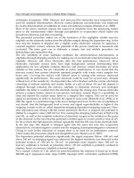
Figure 2 shows the 3d valance shell configuration of iron in its four most important
oxidation states, using ligand field theory, together with the most common values of the
Mössbauer parameters. The ligand field splitting corresponds to the most abundant cases
i.e., octahedral for Fe
II
, Fe
III
and Fe
IV
, and tetrahedral for Fe
VI
. Only high-spin cases (small
ligand field splitting) are discussed.
Fig. 2. Schematic representation of the 3d shell configuration of iron in selected oxidation
states with characteristic Mössbauer parameters. Isomer shifts are given at room
temperature relative to α-Fe, note that, the ligand field splitting corresponding to the most
common octahedral coordination for Fe
II
to Fe
IV
while it is tetrahedral for Fe
VI
[15].
Among regular iron compounds, Fe
II
has the highest isomer shift, and the 3d
6
configuration
of the valence shell represents one more t
2g
electron compared to 3d
5
of spherical symmetry,
thus the quadrupole splitting is also large.
Fe
III
has only five 3d electrons, and therefore the isomer shift becomes smaller. Since the
illustrated 3d splitting is only an idealized non-distorted case, the observed quadrupole
splitting is very rarely zero, it is mostly below 1 mm/s and may even be larger. The
distortion of the octahedron can be caused by the Jahn-Teller effect, lattice symmetry,
neighboring charges, defects, etc.
Waste Water - Treatment and Reutilization
248
Fe
IV
has only four 3d electrons, which is manifested in a further decrease of the isomer shift.
The asymmetry of the 3d density distribution is somewhat similar to the case of Fe
III
but the
quadrupole splitting are surprisingly small or zero. It can be explained if one takes it into
account that with increasing oxidation number, originally ionic states have a tendency to
become covalent and the extra electron which would cause the asymmetry gets delocalized
on the two e
g
sublevels. Zero quadrupole splitting means that the perfect octahedral ligand
environment is preserved.
Fe
VI
cannot exist as a Fe
6+
ion, it should form an oxoanion, FeO
4
2-
. Although ligand field
approximation may not work in this case and MO theory would be more appropriate, the
observed Mössbauer parameters fit in the tendency qualitatively very well, and very low
isomer shift and zero quadrupole splitting found. Distortion of the rather stable tetrahedral
FeO
4
2-
anion is very rarely observed.
The characteristics of alkali and alkaline earth metal ferrate(VI) are shown in Table 2 [16]
which obviously demonstrate that ferrate(VI) basic Mössbauer parameters viz., isomer shift
(δ), reflecting chemical state of iron(VI) changes in narrow limits i.e., 0.87 to 0.91 mm s
-1
(with respect to standard α-Fe). This indicates a weak influence of the outer ion on iron
bonding in oxygen tetrahedron, which is main structural unit of all ferrates(VI).
Property K
3
Na(Fe
VI
O
4
)
2
K
2
Fe
VI
O
4
Rb
2
Fe
VI
O
4
Cs
2
Fe
VI
O
4
K
2
Sr(Fe
VI
O
4
)
2
BaFe
VI
O
4
Δ mm s
-1
-0.89
-0.90
-0.88
-0.89 -0.87 -0.91 -0.90
∆ mm s
-1
0.21 0.0 0.0 0.0 0.14 0.16
H (T,K)
No magnetic
ordering down
to 4.2K
14.2±2.0
(2.8K) 14.7
(0.15K)
14.9±2.0
(2.8K)
15.1±2.0
(2.8K)
8.7 (2.0K)
unresolved
sexlet
11.8±2.0
(2.8K)
T
N
(K) 3.6-4.2 2.8-4.2 4.2-6.0 ~3 7.0-8.0
Table 2. Characteristics of ferrate(VI) [16]
IR spectra of potassium ferrate(VI) showed very characteristic peaks at the wave numbers
324 and 800 cm
-1
(cf Figure 3).
Fig. 3. IR spectrum of potassium ferrate [17].
Ferrate(VI) in the Treatment of Wastewaters: A New Generation Green Chemical
249
Single crystal X-ray structural determination of K
2
FeO
4
was performed and suggested four
equivalent oxygen atoms are covalently bonded to central iron atom in +6 oxidation state
[18]. The tetrahedral structure was also confirmed by isotopic exchange study as performed
in aqueous solutions [19]. The reliable simulated powder XRD patterns (ICSD file 2876 and
32756, [20]) and an experimental one (PDF file No. 25-652, [18]) as reference for the pure
substance is available. Moreover, it was also proposed that Fe(VI) ions can have three
resonance hybrid structures in aqueous solution as shown in figure (4) [21]. Of these three
resonance structures in figure 4, the structures of ‘1’ and ‘2’ were suggested as main
contributors to the resonance structures of Fe(VI) based on theoretical studies of metal oxide
structures.
Fig. 4. Three resonance hybrid structures of Fe(VI) ion in an aqueous solution [21].
Quantitative estimation of Ferrate(VI):
Potassium ferrate K
2
Fe
VI
O
4
, is most common and relatively easily synthesized ferrate salt.
Moreover, the stability of this compound is fairly good under certain specified conditions. It is
black-purple in color and remains stable in moisture excluded air exposure for longer period.
In aqueous solution the ion Fe
VI
O
4
2-
is monomeric with a high degree of four ‘covalent
character’ equivalent oxygen atoms [19,22]. Potassium ferrate is insoluble in commonly used
organic solvents and can be suspended in benzene, ether, chloroform etc. without having
rapid decomposition of compound [23]. Alcohols containing more than 20% water rapidly
decomposed ferrate(VI) and resulted in the formation of aldehydes or ketones [23].
Ferrate(VI) can be easily analyzed quantitatively by the two different methods:
i. Volumetric titration method, and (ii) UV-Visible Spectroscopic method
The brief description of these methods is given below.
i. Volumetric titration method
This method is based on the strong oxidative power of the Fe(VI). In this method, the Fe(VI)
was intended to oxidize the chromite salt (equation 8) and the oxidized chromate was
titrated with the standard ferrous salt solution in an acidic medium, and sodium
diphenylamine sulphonate was used as an indicator [24]. This method is useful to analyze
the solutions containing low concentration of Ferrate(VI) ion in aqueous solutions.
Cr(OH)
4
-
+ FeO
4
2-
+ 3H
2
O → Fe(OH)
3
(H
2
O)
3
+ CrO
4
2-
+ OH
-
(8)
Another method which is developed based on the oxidation of alkaline arsenite to arsenate
using the ferrate(VI) in aqueous solution [25]. The chemical reactions took place given in
equation (9). In this analytical method a known amount of ferrate(VI) was added to a standard
alkaline solution, in which, the amount of arsenite was greater than that required for the
reduction of ferrate(VI) ions. The excess arsenite was back titrated with standard bromate
solution (equation (10)) or cerate solution equation (11). The equivalent of consumed bromate
or cerate is then calculated and subsequently, the equivalent of ferrate was estimated.
Waste Water - Treatment and Reutilization
250
2 FeO
4
2-
+
3AsO
3
3-
+ 11H
2
O + → 2Fe(OH)
3
(H
2
O)
3
+ 3AsO
4
3-
+ 4OH
-
(9)
2BrO
3
-
+ 5AsO
3
3-
+ 2H
+
→ Br
2
+ 5AsO
4
3-
+ H
2
O (10)
2Ce
3+
+ 3AsO
3
3-
+ 6OH
-
→ 2Ce + 3AsO
4
3-
+ 3H
2
O (11)
It was further reported that although, the arsenite-bromate and arsenite-cerate methods
shown equally satisfactory results but the back-titration with cerate is to be preferred
comparing to the bromate titration, since the bromate titration is carried out while the
solution is still hot and the acidity of the hydrochloric acid must be carefully controlled.
However, arsenite-cerate method is not recommended for analyzing highly decomposed
ferrate solutions (that contains large amounts of ferric hydroxide), as the o-phenanthroline
end point is observed by the color of the excess ferric ions [2].
Further, it is to be noted that although the volumetric titration method is useful for
quantitative determination of ferrate(VI), however, the decomposition of ferrate(VI) is rapid
hence, a buffer solution of phosphate is required to maintain pH of the ferrate(VI) sample at
8, at which the self decomposition of ferrate(VI) is significantly suppressed and the results
obtained are more reliable. Moreover, the samples wastes need to be stored and treated
specifically owing to the existence of residual chromite in the wastes if the chromite-ferrous
titration method was employed, or the presence of arsenite if arsenite-bromate/arsenite-
cerate methods were used.
ii. UV-Visible Spectroscopic
This is the most useful and robust method of ferrate(VI) quantification. In this method the
aqueous solution of ferrate, which is red-violet in color and gives a characteristic absorption
maxima at around 500 and 800 nm (cf Figure 5), can be used for its qualitative as well as
quantitative estimation. Moreover, the aqueous solution of ferrate(VI) prepared in
phosphate buffer between pH 9.0 and 10.5 are stable for hours makes it easy to obtain the
spectral measurements at this pH.
Fig. 5. UV-Vis spectrum of potassium ferrate(VI) [25].
Ferrate(VI) in the Treatment of Wastewaters: A New Generation Green Chemical
251
The spectral measurements of FeO
4
2-
were obtained in 0.0075M phosphate solution at different
pH at 25
0
C and it showed that the absorption spectra has a peak at ~510nm. Further, the
accepted value of molar extinction coefficient for FeO
4
2-
at pH 9.0 is 1150 M
-1
cm
1
[26-27,41].
An indirect method of ferrate(VI) determination was proposed using the spectrophotometric
determination [28]. ABTS (2,2'-azino-bis(3-ethylbenzo-thiazoline-6-sulfonate) interacts with
Fe(VI) and gives a green radical cation of ABTS (ABTS
•+
) which showed a characteristic
absorption maxima at 415 nm. This was observed that the increase in absorbance at 415 nm
for the radical ABTS
•+
is linear with the increase in Fe(VI) concentration (0.03 to 35 µM) in
the acetate/phosphate buffer solution at pH 4.3. The molar extinction coefficient was
calculated and found to be 3.40±0.05 x 10
4
M
-1
cm
-1
.
Fig. 6. UV-Vis absorption spectrum of Fe(VI) in aqueous solution as a function of its
concentration, pH = 9.2, 25 mM phosphate buffer [27].
In addition to above said two methods, reports included the chemical precipitation method
of its estimation [29]. In a small glass-stopped bottle, 10 mL of potassium ferrate(VI)
solution was mixed with 20 mL of 0.1 M silver nitrate solution (equation (12)) and the
resulting precipitate was filtered, which contained the silver ferrate and its color was black
with a pink reflection, indicating the presence of potassium ferrate(VI) in the solution. After
heating, the precipitate dissociated into silver oxide, ferric oxide and oxygen (equation (13)).
K
2
FeO
4
+ 2AgNO
3
→ 2KNO
3
+ Ag
2
FeO
4
(12)
4Ag
2
FeO
4
→ 4Ag
2
O + 2Fe
2
O
3
+ 3O
2
(13)
1.4 Stability and speciation of Ferrate(VI)
The stability of ferrate(VI) of its aqueous solutions depends on several factors viz.,
ferrate(VI) concentration, temperature of the solution, co-existing ions, pH etc. [30]. The
dilute solutions of Fe(VI) seems to be more stable than concentrated [31]. The solution of
0.025M Fe(VI) will remain 89% even after the 60 min but if the initial concentration of Fe(VI)
was increased to 0.03 M, almost all the ferrate ions will get decomposed within the same
period of time i.e., 60 min. Other reports also demonstrated that a 0.01M potassium ferrate
Waste Water - Treatment and Reutilization
252
solution decomposed to 79.5% over a period of 2.5 h, while a 0.0019M potassium ferrate
solution decreased to only 37.4% after 3 h and 50 min at 25
0
C [32].
The stability of K
2
FeO
4
in 10 M KOH is increased from hours to week if no Ni
2+
and Co
2+
impurities are present (< 1µM) [33]. However, nitrate salts of Cu
2+
, Fe
3+
, Zn
2+
Pb
2+
, Ba
2+
, Sr
2+
,
Ca
2+
, Mg
2+
and other salts including K
2
Zn(OH)
4
, KIO
4
, K
2
B
4
O
9
, K
3
PO
4
, Na
2
P
2
O
7
, Na
2
SiF
6
,
Na
2
SiO
3
, Na
2
MoO
4
and Na
2
WO
4
have no affect on the stability of K
2
FeO
4
[33]. A 0.5 M K
2
FeO
4
solution, containing KCl, KNO
3
, NaCl and FeOOH was studied to observe the ferrate(VI)
stability in presence of these salts. It was found that the ferrate(VI) decomposed rapidly in the
initial stage and appeared relatively stable at low ferrate concentrations when KCl and KNO
3
were present [31]. Phosphate was shown to retard the ferrate(VI) decomposition.
The spontaneous decomposition of ferrate(VI) in aqueous solutions was reported to be
increased significantly with decreasing the solution pH. Figure 7 obtained with using the 1
mM solution of K
2
FeO
4
in aqueous solution showed that at pH ~5, just after 7 min, the
Fe(VI) was decomposed completely, however, at pH ~9 and ~10, it was fairly stable even
after elapsed time of 20 min [34]. Other studies, conducted with 2h test period, the
concentration of potassium ferrate slightly decreased when it was in 6M KOH, but
decreased rapidly when it was in 3M KOH. The ferrate solution prepared with buffer
solution at pH 8 was more stable than that prepared at pH 7 [31]; 49% of the original
potassium ferrate remained after 8 h when the pH was 7, and 71.4% of that remained after
10 h when the pH was 8.
Fig. 7. The change of the Fe(VI) concentration as a function of time at various pH values
[Initial concentration of Fe(VI): 1 mM] [34].
Temperature dependence data showed that ferrate(VI) solutions are relatively stable at low
temperature conditions (0.5
0
C) [32]. The 0.01 M solution of Fe(VI) was reduced by 10% at a
constant temperature of 25
0
C and almost unchanged at 0.5
0
C for a period of 2 h.
Speciation and Decomposition of Fe(VI)
The presence of at least two unstable protonated form of Fe(VI) i.e., H
2
FeO
4
and HFeO
4
-
was reported in 0.2 M phosphate buffer solutions at 25
0
C [35]. However, a similar study in
0.025 M phosphate/acetate buffers at 23
0
C showed three protonated forms of Fe(VI)
Ferrate(VI) in the Treatment of Wastewaters: A New Generation Green Chemical
253
(equations (14-16)) [36]. The pk
a
for HFeO
4
-
/FeO
4
2-
(equation (16)) were also found different
in the two different studies. The discrepancy in pk
a
3
was attributed to the difference in the
buffer concentrations used.
H
3
FeO
4
+
↔ H
+
+ H
2
FeO
4
(pk
a
1
= 1.6±0.2 [36]) (14)
H
2
FeO
4
↔ H
+
+ HFeO
4
-
(pk
a
2
= 3.5 [35, 36]) (15)
HFeO
4
-
↔ H
+
+ FeO
4
2-
(pk
a
3
= 7.3±0.1 [36]; 7.8 [35]) (16)
These pKa values indicated that the presence of four different ferrate(VI) species in the
entire pH range (Figure 8). Figure 8 clearly indicated that HFeO
4
-
and FeO
4
2-
species are
predominant species in neutral and alkaline solutions, at which the Fe(VI) was known to be
relatively stable towards its spontaneous dissociation [37].
Fig. 8. Speciation of ferrate(VI) in aqueous solutions [Concentration of Fe(VI): 1mM] [34].
The ferrate salts when dissolved in water, oxygen is evolved and ferric hydroxide is
precipitated (equation (14)).
4K
2
FeO
4
+ 10H
2
O → 4Fe(OH)
3
+ 8KOH + 3O
2
(14)
The rate of decomposition of ferrate(VI) has already seen that it is strongly pH dependent.
The lowest rate of decomposition was occurred at pH higher than ~9-10, while it increased
significantly at lower pH values [35,38]. The reaction kinetics followed second-order below
pH 9.0, while first order above pH 10.0 [37]. The decomposition of ferrate(VI) hence,
described by the following equilibrium and kinetic models [36]:
2H
3
FeO
4
+
↔ [H
4
Fe
2
O
7
]
2+
+ H
2
O k
15
= 3.5x10
5
M
-1
s
-1
(15)
[H
4
Fe
2
O
7
]
2+
+
2H
+
+ 6H
2
O → Fe
2
(OH)
2
(H
2
O)
8
4+
+ 3/2 O
2
Fast step (16)
H
3
FeO
4
+
+ H
2
FeO
4
↔ [diferrate] k
17
≈ 3.5x10
5
M
-1
s
-1
(17)
2H
2
FeO
4
↔ [diferrate] k
18
= 1.5x10
4
M
-1
s
-1
(18)
H
2
FeO
4
+ HFeO
4
-
↔ [diferrate] k
19
≈ 1.5x10
4
M
-1
s
-1
(19)