Wind_Farm Technical Regulations Potential Estimation and Siting Assessment Part 2 potx
Bạn đang xem bản rút gọn của tài liệu. Xem và tải ngay bản đầy đủ của tài liệu tại đây (480.96 KB, 20 trang )
Technical and Regulatory Exigencies for Grid Connection of Wind Generation
9
turbines are destroyed, is in the range of 40–72 m/s (144–259 km/h, or 89–161 mph). The
most common survival speed of commercial wind turbines is around 60 m/s (216 km/h or
134 mph).
Wind turbines have three modes of operation (Hansen et al., 2004).):
• Below rated wind speed operation
• Around rated wind speed operation (usually at nominal capacity)
• Above rated wind speed operation
If the rated wind speed is exceeded the power has to be limited. Therefore, all wind turbines
are designed with a power control that achieves this goal and avoids a run-away situation.
There are different ways of doing this safely on modern turbines, namely mainly pitch
control and stall control.
3.2.3.1 Pitch control
This control concept was developed between years 1990 and 2000 and operates by turning
the rotor blades into or out of the wind according to the control laws. An anemometer
mounted atop the nacelle constantly checks the wind speed and sends signals to the pitch
actuator, adjusting the angle of the blades to capture the energy from the wind most
efficiently.
Standard modern turbines usually pitch the blades at high winds in order to prevent the
rotational speed from rising to an unacceptably dangerous level. Since pitching requires
acting against the torque on the blade, it requires some form of pitch angle control, which is
achieved with a slewing drive. This drive precisely angles the blade while withstanding
high torque loads. In addition, many turbines use hydraulic systems. These systems are
usually spring loaded, so that if hydraulic power fails, the blades automatically furl. Other
turbines use an electric servomotor for every rotor blade. They have a small battery-reserve
in case of an electric grid breakdown. Small wind turbines (fewer than some kWs) with
variable pitching generally use systems operated by centrifugal force, either by flyweights
or geometric design, and employ no electric or hydraulic controls.
In a pitch controlled wind turbine, the electronic controller checks the power output of the
turbine several times per second. When the power output becomes too high, it sends an
order to the blade pitch mechanism which immediately pitches (turns) the rotor blades
slightly out of the wind. On the other hand, the blades are turned back into the wind
whenever the wind drops again. The rotor blades thus have to be able to turn around their
longitudinal axis (to pitch).
During normal operation (below or around rated wind speed) the controller generally
pitches the blades a few degrees every time the wind changes in order to keep the rotor
blades at the optimum angle in order to maximize output at all wind speeds.
3.2.3.2 Stall control
In a stall-regulated wind turbine, the blades are locked in place and do not adjust during
operation. Instead the blades are aerodynamically designed and shaped to increasingly
“stall” the blade angle of attack with the wind to both maximize power output and protect
the turbine from excessive wind speeds. As the actual wind speed in the rotor area increases
the angle of attack of the rotor blade also increases, until at some point it starts to stall. Thus,
it is ensured that at the moment the wind speed becomes too high, it creates turbulence on
the side of the rotor blade which is not facing the wind and prevents the lifting force of the
rotor blade from acting on the rotor.
Wind Farm – Technical Regulations, Potential Estimation and Siting Assessment
10
Stalling works by increasing the angle at which the relative wind strikes the blades (angle of
attack), and it reduces the induced drag (drag associated with lift). Stalling is simple because
it can be made to happen passively (it increases automatically when the winds speed up), or
actively (the rotor blade angle is adjusted or pitched in order to create stall along the blades).
Active stall regulation allows for power to be regulated more accurately than passive stall
regulation does.
The main advantage of stall control is that it avoids moving parts in the rotor itself, and
therefore a complex control system since they do not have the same level of mechanical and
operational complexity as pitch-regulated turbines. In this way, stall-regulated turbines are
often considered more reliable than pitch-regulated ones. On the other hand, stall control
represents a very complex aerodynamic design problem, and related design challenges in
the structural dynamics of the whole wind turbine, e.g. to avoid stall-induced vibrations. In
addition, pitch-regulated wind turbines are generally considered to be slightly more
efficient than stall-regulated ones. Around two thirds of the wind turbines currently being
installed in the world are stall controlled machines.
3.2.3.3 Other power control methods
Some older wind turbines use ailerons (flaps) to control the power of the rotor, just like
aircraft use flaps to alter the geometry of the wings to provide extra lift at takeoff. Another
possibility is to yaw the rotor partly out of the wind to decrease power. This technique of
yaw control is in practice used only for tiny wind turbines (1 kW or less), as it subjects the
rotor to cyclically varying stress which may ultimately damage the entire structure. Braking
of a small wind turbine can also be done by dumping energy from the generator into a
resistor bank, converting the kinetic energy of the turbine rotation into heat. This method is
useful if the kinetic load on the generator is suddenly reduced or is too small to keep the
turbine speed within its allowed limit. Cyclically, braking causes the blades to slow down,
which increases the stalling effect, reducing the efficiency of the blades. In this way, the
turbine rotation can be kept at a safe speed in faster winds while maintaining (nominal)
power output. This technique is also used only for tiny wind turbines and cannot be applied
for large wind turbines.
3.3 Nacelle with drive train and other equipment
The nacelle contains all the machinery of the wind turbine, i.e. the drive train including the
mechanical transmission (rotor shaft, bearings and the gearbox) and the electrical generator,
and other equipment such as the power electronic interface, the yaw drive, the mechanical
brake, and the control system, among others. Because it requires rotating in order to track
the wind direction, it is connected to the tower via bearings. The build-up of the nacelle
shows how the manufacturer has decided to place the drive train and other components
above this machine bearing.
3.3.1 Drive train
3.3.1.1 Mechanical transmission
The gearbox is the major component of the mechanical transmission. Due to their huge
diameters, the rotors of large scale wind turbines tend to have very slow rotational speeds
(generally 18–50 rpm). In most cases, these speeds are insufficient to operate their generators
at maximum efficiency (for most generators, somewhere in the range of 1200–1800 rpm).
Technical and Regulatory Exigencies for Grid Connection of Wind Generation
11
The solution is to include a gearbox transmission between the rotor output shaft and the
generator input shaft so that the rotor speed can be geared up to the appropriate rpm
required by the generator for maximum power generation. In the case of multi-pole
synchronous generators coupled to the electric grid via a full scale power converter, which
decouples entirely the generator system from the utility grid, since it can operate at low
speeds the gearbox can be omitted. Consequently, a gearless construction represents an
efficient and robust solution that is beneficial, especially for offshore applications, where
low maintenance requirements are essential. In the case of wind turbines with smaller rotor
diameters, the gearbox transmission between the rotor and generator can be also omitted. A
decrease in rotor diameter results in a smaller arc-length that the rotor must travel per
revolution, eventually causing a comparatively larger rotational speed than that of a larger
rotor for a given wind speed. If these larger rotational speeds are appropriate for the type of
generator being used, the rotor can be connected straightforwardly to the generator
resulting in a direct-driven system in the same way as in the system linked with the power
converter. These smaller direct-driven wind turbine systems are predominately used in
stand-alone (not grid-connected) DC applications (battery charging, etc).
3.3.1.2 Electrical generator
The generator is the component of the wind turbine responsible for converting the
mechanical motion of the rotor into electrical energy. The blades transfer the kinetic energy
from the wind into rotational energy in the transmission system, and the generator is the
next step in the supply of energy from the wind turbine to the electrical grid.
There are many different types and sizes of electric generators for a wide range of
applications. Depending on the size of the rotor and the amount of mechanical energy
removed from the wind, a generator may be chosen to produce either AC or DC voltage
over a variety of power outputs.
There are two major types of electrical generators for converting mechanical energy. The
first is the synchronous generator. The synchronous generator operates on the principle that
as a magnet is rotated in the presence of a coil of wire, the changing magnetic field in space
induces a current, and therefore a voltage in the coil of wire. In this case, the magnet is
attached to the input shaft of the generator and is surrounded by several coils of wire,
individually referred to as a pole. As the shaft rotates, so does the permanent magnet which
creates a changing magnetic field in the presence of the poles which surround it. This
induces a current in each of these poles and electrical energy is produced. Synchronous
generators are typically quite simple and can be used in a wide variety of applications.
The second type is the asynchronous generator. At the heart of this design is its rotor, which
is essentially a cylindrical cage of copper or aluminium bars that concentrically surround an
iron core. This rotor construction looks a bit like a squirrel cage, and accordingly the
asynchronous generator is also called a squirrel cage generator. Once again, this rotor is
surrounded by a series of poles on its periphery called the stator. One way in which the
asynchronous generator varies from the synchronous one is in that it is actually powered by
the grid to set itself into motion initially. As the current from the grid passes through the
stator, a current is induced in the cage rotor itself; causing opposing magnetic fields that set
the rotor in motion at a specific rotational speed (this speed is determined by the frequency
of the supply current and the number of poles in the stator). The generation of electricity
occurs when the wind causes the rotational speed of the rotor to increase above this idle
speed caused by the grid. What is fascinating about this phenomenon is that very large
Wind Farm – Technical Regulations, Potential Estimation and Siting Assessment
12
voltages can be produced for comparatively small increases in rotational speed
(considerable voltage for 10–15 rpm increase). With the rotor already in motion, there is little
torque applied to the rotor shaft, ultimately resulting in less wear on the transmission.
However, the asynchronous generator is much more complex that the synchronous one and
also requires an initial source of power to operate. Asynchronous generators are more
appropriate for applications where there is a fairly constant wind speed that rarely drops
below a certain value.
3.3.2 Other equipment
3.3.2.1 Power electronic converter
Power electronic systems are used by many wind turbines as interfaces. Wind turbines
function at variable rotational speed; thus the generator electric frequency varies and needs
to be decoupled from the grid frequency through a power electronic converter system.
The power electronic converter enables wind turbines to operate at variable (or adjustable)
speed, and thus permits to provide more effective power capture than the fixed-speed
counterparts. In variable speed operation, a control system designed to extract maximum
power from the wind turbine and to provide constant grid voltage and frequency is
required according to the type of wind turbine used. With the advance of power electronics
technology, this objective is easy to be accomplished, as will be noted from description of
the subsequent section.
The power converter is an interface found between the load/generator and the grid.
Depending on the topology and the applications present in the system, power can flow into
the direction of both the generator and the grid. In using converters, three important things
must be considered: reliability, efficiency, and cost.
Converters are made by power electronic devices, and circuits for driving, protection and
control. Two different types of converter systems are currently in use: grid commutated and
self commutated converters. Grid commutated converters are thyristor converters
containing 6 or 12 pulse, or even more, that can produce integer harmonics. This kind of
converter does not control the reactive power and consume inductive reactive power.
The other type of converter, self-commutated converter systems, are pulse width modulated
(PWM) converters that mainly use Insulated Gate Bipolar Transistor (IGBTs). In contrast to
grid-commutated, self-commutated converters control both active and reactive powers.
PWM-converters, therefore, have the capacity to provide for the demand on reactive power
and a high frequency switching that make them produce high harmonics and
interharmonics.
3.3.2.2 Yaw drive
The yaw drive is an important component of modern horizontal axis wind turbines yaw
system. To ensure the wind turbine is producing the maximum amount of electric energy at
all times, the yaw drive is actively controlled to keep the rotor facing into the wind as the
wind direction changes. This is accomplished by measured the wind direction by a wind
vane situated on the back of the nacelle. The wind turbine is said to have a yaw angle (the
misalignment between wind and turbine pointing direction) error if the rotor is not aligned
to the wind. A yaw error implies that a lower share of the energy in the wind is running
through the rotor area. The power output losses are proportional to the cosine of the yaw
error.
Technical and Regulatory Exigencies for Grid Connection of Wind Generation
13
3.3.2.3 Mechanical brake
A wind turbine has two different types of brakes. One is the blade tip brake and the other is
a mechanical (or stick) brake. The mechanical brake is placed on the small fast shaft between
the gearbox and the generator. This mechanical drum brake or disk brake is only used as an
emergency brake, if the blade tip brake fails. The brake is also used when the wind turbine is
being repaired to eliminate any risk of the turbine suddenly starting. Such brakes are
usually applied only after blade furling and electromagnetic braking have reduced the
turbine speed, as the mechanical brakes would wear quickly if used to stop the turbine from
full speed.
3.3.2.4 Control system
The wind turbine control system is involved in almost all decision-making processes in the
safety of the wind turbine. At the same time, it must supervise the normal operation of the
wind turbine and carry out the measurements for monitoring, control, statistical use, etc.
The control system is usually based on a number of dedicated computers, specially designed
for industrial use, which continuously monitor the condition of the wind turbine and collect
statistics on its operation. As the name implies, the controller also controls a large number of
switches, hydraulic pumps, valves, and motors within the wind turbine. As wind turbine
sizes increase to megawatt machines, it becomes even more important that they have a high
availability rate, i.e. that they function reliably all the time.
A series of sensors measure the conditions in the wind turbine. These sensors are usually
employed for measuring temperature, wind direction, wind speed, rotational speed of the
rotor, the generator, its voltage and current, and many other magnitudes can be found in
and around the nacelle (somewhere between 100 and 500 parameter values are sensed in a
modern wind turbine), and assist in the turbine control. Computers and sensors are usually
duplicated (redundant) in all safety or operation sensitive areas of newer large machines.
The controller continuously compares the readings from measurements throughout the
wind turbine to ensure that both the sensors and the computers themselves are correctly
operating.
4. Wind turbine concepts
Wind turbines can either be designed to operate at fixed speed (actually within a speed
range about 1%) or at variable speed. Many low-power wind turbines built to-date were
constructed according to the so-called “Danish concept” that was very popular in the 80s, in
which wind energy is transformed into electrical energy using a simple squirrel-cage
induction machine directly connected to a three-phase power grid (Qiao et al., 2007). The
rotor of the wind turbine is coupled to the generator shaft with a fixed-ratio gearbox. At any
given operating point, this turbine has to be operated basically at constant speed. On the
other hand, modern high-power wind turbines in the 2-10 MW range are mainly based on
variable speed operation with blade pitch angle control obtained mainly by means of power
electronic equipment, although variable generator rotor resistance could also be used.
Variable speed wind turbine generators permits to provide more effective power capture
than the fixed speed counterparts (Timbus et al., 2009). In fact, variable speed wind turbines
have demonstrated to capture 8-15% more energy than constant speed machines. In variable
speed operation, a control system designed to extract maximum power from the wind
turbine and to provide constant grid voltage and frequency is required. As well as becoming
Wind Farm – Technical Regulations, Potential Estimation and Siting Assessment
14
larger, wind turbine designs were progressing from fixed speed, stall-controlled and with
drive trains with gear boxes to become pitch controlled, variable speed and with or without
gearboxes.
Among variable speed wind turbines, direct-in-line systems and doubly-fed induction
generator (DFIG) systems have increasingly drawn more interests to wind turbine
manufactures due to their advantages over other variable speed wind turbines and
currently have the most significant potential of growth (Molina & Mercado, 2011). Direct-in-
line systems consists of a direct-driven (without gearbox) permanent magnet synchronous
generator (PMSG) grid-connected via a full-scale power converter, while DFIG systems are
built with a common induction generator with slip ring and a partial-scale converter
connected to the rotor windings. Both modern pitch-controlled variable speed wind turbines
technologies are emerging as the preferred technologies and have become the dominating
type of yearly installed wind turbines in recent years (Blaabjerg & Chen, 2006).
4.1 Variable speed wind turbine with partial-scale power converter
This concept, aka doubly-fed induction generator (DFIG), corresponds to a variable speed
controlled wind turbine with a wound rotor induction generator (WRIG) and a partial-scale
power converter (rated approximately at 30% of nominal generated power) on the rotor
circuit (Muller et al, 2002), as shown in Fig. 2. The use of power electronic converters enables
wind turbines to operate at variable (or adjustable) speed, and thus permits to provide more
effective power capture than the fixed-speed counterparts (Blaabjerg et al. 2004). In addition,
other significant advantages using variable speed systems include a decrease in mechanical
losses, which makes possible lighter mechanical designs, and a more controllable power
output (less dependent on wind variations), cost-effectiveness, simple pitch control,
improved power quality and system efficiency, reduced acoustic noise, and island-operation
capability.
The rotor stator is directly connected to the electric grid, while a partial-scale power
converter controls the rotor frequency and consequently the rotor speed. The partial-scale
power converter is composed of a back-to-back four-quadrant AC/DC/AC converter design
based on insulated gate bipolar transistors (IGBTs), whose power rating defines the speed
range (typically around ±30% of the synchronous speed). Moreover, this converter allows
controlling the reactive power compensation and a smooth grid connection (Carrasco et al.,
2006). The partial-scale power converter makes this concept attractive from an economical
point of view. However, its main drawbacks are the use of slip rings, which needs brushes
and maintenance, and the complex protection schemes in the case of grid faults.
4.2 Direct-in-line variable speed wind turbine with full-scale power converter
This configuration corresponds to the direct-in-line full variable speed controlled wind
turbine, with the generator connected to the electric grid through a full-scale power
converter, as illustrated in Fig 3 (Li et al., 2009). A synchronous generator is used to produce
variable frequency AC power. The power converter connected in series (or in-line) with the
wind turbine generator transforms this variable frequency AC power into fixed-frequency
AC power. This power converter also allows controlling the reactive power compensation
locally generated, and a smooth grid connection for the entire speed range. The generator
can be electrically excited (wound rotor synchronous generator, WRSG) or permanent
magnet excited type (permanent magnet synchronous generator, PMSG). Recently, due to
Technical and Regulatory Exigencies for Grid Connection of Wind Generation
15
the development in power electronics technology, the squirrel-cage induction generator
(SCIG) has also started to be used for this concept. The generator stator is connected to the
grid through a full-scale power converter, which is composed of a back-to-back four-
quadrant AC/DC/AC converter design based on insulated gate bipolar transistors (IGBTs).
Fig. 2. Variable speed wind turbine with doubly-fed induction generator (DFIG) controlled
with a partial-scale power converter
Some full variable speed wind turbine systems have no gearbox (shown in dotted lines in
Fig. 3) and use a direct driven multi-pole generator.
Fig. 3. Variable speed wind turbine with permanent magnet synchronous generator (PMSG)
controlled with a full-scale power converter
Direct-in-line variable speed wind turbines have several drawbacks respect to the former
variable speed DFIG concepts, which mainly include the power converter and output filter
ratings at about 1 p.u. of the total system power. This feature reduces the efficiency of the
Wind Farm – Technical Regulations, Potential Estimation and Siting Assessment
16
overall system and therefore results in a more expensive device. However, as the full scale
power converter decouples entirely the wind turbine generator from the utility grid, grid
codes such as fault ride through and grid support are easier to be accomplished, as required
from modern applications. In addition, since a direct-in-line system can operate at low
speeds, the gearbox can be omitted (direct-driven). Consequently, a gearless construction
represents an efficient and robust solution that is beneficial, especially for offshore
applications, where low maintenance requirements are essential. Moreover, using a
permanent magnet synchronous generator, the DC excitation system is eliminated and
allows reducing weight, losses, costs, and maintenance requirements (no slip rings are
required). Even more, due to the intensified grid codes around the world, direct-driven
PMSG wind turbine systems could be favoured in the future compared to DFIG wind
turbine concepts (Li et al., 2009).
5. Technical exigencies for grid connection of wind generation
Any customer connected to a public utility electric network, whether generator or consumer,
have to comply with agreed technical exigencies (aka demands or requirements) in order for
the power grid to operate securely and efficiently. Electric power systems rely on generators
to provide many of the control functions, and so the technical exigencies for generators are
inevitably more complex than for demand customers. These technical requirements are
often called “grid codes”, although the term should be used with care, as there are often
different codes, depending on the voltage level of connection or the size of the application.
In addition, there may be technical requirements that are not referred to the grid code, but
which apply to the project through the connection agreement or the power purchase
agreement or in some other way. Grid codes or interconnection guidelines can be
summarized as a technical document containing the rules governing the operation,
maintenance and development of the transmission system.
Large-scale penetration of wind generation may present a significant power contribution to
the electric grid, and thus play an important role in power system operation and control
(Slootweg & Kling, 2003). Consequently, high technical demands are expected to be met by
these generation units. The purpose of these technical requirements is to define the technical
characteristics and obligations of wind generators and the system operator (Martínez de
Alegría et al. 2007), meaning that:
• Electric system operators can be confident that their system will be secure regardless of
the wind generation projects and technologies applied.
• The amount of project-specific technical negotiation and design is minimised.
• Equipment manufacturers can design their equipment in the knowledge that the
requirements are clearly defined and will not change without warning or consultation.
• Project developers have a wider range of equipment suppliers to choose from.
• Equivalent projects are treated fairly.
• Different wind generator technologies are treated equally.
This section includes the technical exigencies encountered in the majority of grid codes
concerning wind generation interconnection. These include fault ride-through capability,
system voltage and frequency operating range, reactive power and voltage regulation,
active power regulation and frequency control as well as voltage flicker emission and
harmonics emission.
Technical and Regulatory Exigencies for Grid Connection of Wind Generation
17
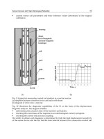
5.1 Fault Ride-Through (FRT) capability
An important issue when integrating large-scale wind generation is the impact on the
system stability and the transient behaviour. System stability is mainly associated with
power system faults in the network such as tripping of transmission lines, loss of generation
(generating unit failure) and short circuit. These failures disrupt the balance of power (active
and reactive) and change the power flow. Although the capacity of the operating generators
can be suitable, large voltage drops can occur suddenly and can propagate over very wide
areas, affecting a great number of wind generators. The unbalance and re-distribution of
active and reactive power in the network can force the voltage to vary beyond the boundary
of stability. A period of low voltage (brownout) can occur and possibly be followed by a
complete loss of power (blackout). (Jauch et al., 2004; Chen & Blaabjerg, 2009; Tsili &
Papathanassiou, 2009).
Many faults in the power system are cleared by relay protections either by disconnection or
by disconnection plus fast reclosing. In all the situations the result is a short period of low or
no voltage followed by a period of voltage recovering. Some decades ago, when just a few
wind turbines were connected to the grid, if a fault somewhere in the grid caused a short
voltage drop at the wind turbine (aka voltage sag or dip), the wind turbine was simply
disconnected from the electrical grid and had to be reconnected again when the fault was
cleared and the voltage returned to the normal values. Because the penetration of wind
generation in those days was low, the sudden disconnection of a wind turbine or even a
wind farm from the grid did not cause a significant impact on the stability of the power
system. With the increasing penetration of wind generation, the contribution of power
generated by wind turbines is becoming a significant issue. If a large wind farm (or park) is
abruptly disconnected when operates at full-rate, the power system will loss further
production capability. Unless the remaining operating power plants have enough spinning
reserve, in order to replace the lost power within very short time, a large power disturbance
can occur and possibly be followed by a complete loss of power. It is, therefore, an essential
requirement that wind generation is able to remain connected to the system during a power
system fault, where the voltage on all three phases could fall to prevent extra generation
losses. If wind generators are not able to ride-through voltage dips, the system will need a
larger spinning reserve with consequent higher operating costs in order to avoid the system
collapse because of the increasingly frequency drop.
The large increase in the installed wind capacity in transmission systems, especially in the
last decade, requires that wind generation remains in operation in the case of disturbances
and faults in the power system. For this reason, grid codes issued during the last years
invariably demand that wind generation (especially those connected to high voltage grids)
withstand voltage dips to a certain percentage of the nominal voltage (down to 0-15%) and
for a specified duration (according to the country regulations). Such requirements are
known as Fault Ride-Through (FRT) or Low Voltage Ride-Through (LVRT) capabilities and
are described by a voltage vs. time characteristic such as the one shown in Fig. 4, denoting
the minimum required immunity of the wind power generator (Kim & Dah-Chuan Lu,
2010). The FRT requirements under voltage dip is one of the main focuses of the grid codes
and also include fast active and reactive power restoration to the pre-fault values, after the
system voltage returns to its normal operation levels. Some codes impose increased reactive
power generation by the wind turbines during the disturbance, in order to provide voltage
support, a requirement that resembles the behaviour of conventional synchronous
Wind Farm – Technical Regulations, Potential Estimation and Siting Assessment
18
generators in over-excited operation. The requirements depend on the specific
characteristics of each power system and the protection employed and they deviate
significantly from each other.
Fig. 4. Typical fault ride-through capability of a wind power generator
As previously described, the latest grid codes require that wind farms must remain in
operation during severe grid disturbances, ensure fast restoration of active power to the pre-
fault levels, as soon as the fault is cleared, and in certain cases produce reactive current in
order to support grid voltage during disturbances. Depending on their type and technology,
wind turbines can fulfil these requirements to different degrees.
In the case of fixed (constant) speed wind turbines, their low voltage behaviour is
dominated by the presence of the direct grid-connected induction generator. In the event of
a voltage dip, the generator torque reduces considerably (roughly by the square of its
terminal voltage) resulting in the acceleration of the rotor, which may result in rotor
instability, unless the voltage is restored fast or the accelerating mechanical torque is rapidly
reduced. Further, operation of the machine at increased slip values results in increased
reactive power absorption, particularly after fault clearance and partial restoration of the
system voltage. This effectively prevents fast voltage recovery and can affect other
neighbouring generators, whose terminal voltage remains depressed. Since the dynamic
behaviour of the induction generator itself cannot be improved, a measure that can be
employed in order to enhance the FRT capabilities of constant speed wind turbines is to
supply reactive power through switched capacitors or static compensation devices
connected at the wind turbine or wind farm terminals.
On the other hand, variable speed wind turbines, present the distinct advantages of direct
generator torque and reactive current control and the possibility to endure large rotor speed
variations without stability implications. For this reason, grid disturbances affect much less
their operation and, generally, they are capable of meeting strict technical requirements.
In case of voltage disturbances, rotor overspeed becomes an issue of much smaller
significance, since a limited increase of speed is possible (e.g. 10-15% above rated), the rotor
inertia acting as an energy buffer for the surplus accelerating power, until the pitch
Technical and Regulatory Exigencies for Grid Connection of Wind Generation
19
regulation becomes effective. In case of severe voltage dips, an energy surplus may occur in
the electrical part, potentially leading to DC overvoltages. This is dealt with via proper
redesign of the converter controllers, increase of the local energy storage capacity (e.g.
capacitor size) or even by providing local power dissipation means. However, even with
variable speed wind turbines there still exist LVRT issues affecting their response. In the
case of DFIG wind turbines, the direct connection of the generator stator to the grid
inevitably results in severe transients in case of large grid disturbances. Hence, the stator
contributes a high initial short circuit current, while large currents and voltages are also
induced in the rotor windings, as a consequence of the fundamental flux linkage dynamics
of the generator. Furthermore, the depressed terminal voltage reduces accordingly the
power output of the grid side rotor converter, leading to an increase of the DC bus capacitor
voltage. To protect the power converters from overvoltages and overcurrents, DFIGs are
always equipped with a device known as a crowbar that short-circuits the rotor terminals as
soon as such situations are detected. Once the crowbar is activated, the DFIG behaves like a
conventional induction machine, i.e. control is lost over the generator. Notably, crowbar
activation is possible not only at the instant of a voltage depression, but also in case of
abrupt voltage recovery, after clearance of a fault. Hence, although voltage dips inevitably
cause torque and power transients in the DFIG wind turbine, which excite the rotor crowbar
protection for a limited time interval, the various implementations of the active crowbar can
improve the stability of the wind turbine and its response to sudden voltage changes.
Variable speed wind turbines with full-scale power converter present the distinct advantage
that the converter totally decouples the generator from the grid. Hence, grid disturbances
have no direct effect on the generator, whose current and torque variations during voltage
dips are much lower compared to the DFIG and the respective transients fade out faster.
From the point of view of the reactive output power, the grid side converter has the ability
to produce reactive current during the voltage dip, up to its rated current. Notably, this
wind turbine type can exhibit better voltage control capabilities even than conventional
synchronous generators. Another notable advantage of this type against the DFIG-based
wind turbines is related with the behaviour of the latter in case of unbalanced disturbances.
In such situations, the low negative sequence impedance of the induction generator may
give rise to large rotor currents, whose frequency lies outside the controllers bandwidth,
resulting in the activation of the crowbar (or the disconnection of the stator) until the
disturbance is cleared. Wind turbines can control their active power output by pitch control,
while variable speed wind turbines have the additional capability for such control via
variation of their rotor speed. Hence, power restriction, ramp rate limitations and
contribution to frequency regulation is possible, even for constant speed machines.
However, in the latter case the grid frequency is directly related to the generator slip and
hence a change in frequency will transiently affect the active power produced by the wind
turbine. In contrast, in the case of variable speed machines the generator power is directly
controlled and therefore their primary frequency response is entirely adjustable via proper
design of the control systems.
5.2 Voltage and frequency operating range
Wind farms must be capable of operating continuously within the voltage and frequency
variation limits encountered in normal operation of the system. In addition, they should
remain in operation in case of voltage and frequency excursions outside the normal
operation limits, for a limited time and in some cases at reduced output power capability.
Wind Farm – Technical Regulations, Potential Estimation and Siting Assessment
20
Tolerance to voltage variations in power systems depends on the level at the point of
common coupling (PCC) of the wind power generator connected to the network.
Transmission level voltages are usually considered to be 115 kV and above. Lower voltages
such as 66 kV and 33 kV are usually considered sub-transmission voltages. Voltages less
than 33 kV are usually used for distribution. Voltages above 230 kV are considered extra
high voltage and require different designs compared to equipment used at lower voltages.
The operating voltages at each voltage level are highly dependent on the local conditions
and can be different in various countries. The lowest values are reached during operational
disturbances and are usually not lower than 90% of the nominal voltage in the transmission
level and can be down in some countries to 70% of the initial voltage for duration of up to 10
seconds, which must not lead to instability of the wind farm. Voltages above the upper limit
for full-load voltage range is rarer and occurs for instance by reestablishment of the supply
after major operational disturbances. These highest values are typically not higher than
113% in the transmission level. The system voltage operating range is generally narrower for
higher voltage levels.
The frequency is one of the most important parameters in all power networks. The
frequency of the electrical system varies by country; most electric power is generated at
either 50 or 60 Hz. All the generating equipments in the electric system are designed to
operate within very strict frequency margins. Grid codes specify that all generating plants
should be able to operate continuously between a frequency range around the nominal
frequency of the grid, usually between 49.5 and 50.5 Hz (for 50 Hz systems such as in
Europe), and to operate for different periods of time when lower/higher frequencies
down/up to a minimum/maximum limit, typically 47.5 and 52 Hz. Operation outside these
limits would damage the generating plants, so even very short duration deviations from the
nominal frequency values would trip load shedding relays and generation capacity would
be lost. The lost of generation leads to further frequency deviation and a blackout can occur.
Wind farms have to be dimensioned to generate power at voltages and frequencies deviated
from rated values in the way indicated in Fig. 5, showing the power restriction in different
operating areas (Eltra & Ekraft System, 2004). In this diagram, V
L
is the lower voltage limit
while V
LF
is the lower voltage limit for full-load range for a nominal voltage V
N
. In the same
way, V
H
is the upper voltage limit while V
HF
is the upper voltage limit for full-load range.
These voltage limits in a 132 kV (V
N
) transmission grid may have values such as 119 kV for
V
L
,
125 kV for V
LF
, 145 kV for V
H
and 155 kV for V
HF
for the case of the Danish system. The
full-load range indicates the voltage range within which the wind farm can supply its
nominal power without any restriction (continuous operation area).
5.3 Reactive power control and voltage regulation
Reactive power control is very significant for wind farms, because not all wind generation
technologies have the same capabilities, while wind farms are often installed in remote areas
and therefore reactive power has to be transported over long distances resulting in power
losses. Some wind farms are required to have sufficient reactive power compensation to be
neutral in reactive power at any operating point. Recent grid codes demand from wind
farms to provide reactive output regulation, often in response to power system voltage
variations, much as the conventional power plants.
The reactive power control requirements are related to the characteristics of each network
and the voltage level considered, since the influence of the reactive power injection on the
Technical and Regulatory Exigencies for Grid Connection of Wind Generation
21
Fig. 5. Typical voltage and frequency dimensioning for wind generators
voltage profile is directly determined by the short-circuit capacity and impedance at the
PCC of the wind farm. The short-circuit capacity at a given point in the electrical network
represents the system strength or robustness. It is clear that the variations of the generated
power result in variations of the voltage at PCC. If the impedance is small (the grid is
strong) then the voltage variations are small. On the other hand, if the impedance is large
(the grid is weak), then the voltage variations are large.
Voltage is closely related to the reactive power; consequently wind turbines with the ability
of controlling reactive power can support and regulate the PCC local system voltage.
Modern large wind farms are required to have the ability of controlling both active and
reactive power. In the case of the fixed speed wind turbines with conventional induction
generators, the reactive power can be controlled by thyristor-switched capacitor banks.
Furthermore, a dynamic reactive power control unit based on power converters can
additionally be installed at the PCC although at higher costs. In the case of power electronic
converter-based variable speed wind turbines, such as those with DFIG systems or with full-
scale power converters, the reactive power control can be performed by the converter itself.
Consequently, significant active power fluctuations from the wind speed variations may not
lead to corresponding fluctuations of the grid voltage at the connection point of the wind
farm. Some codes recommend that the transmission system operators (TSOs) may define a
set-point value for voltage or power factor or reactive power at the PCC of the wind farm.
A Voltage Regulator (VR) is included in modern wind generator in order to determine its
terminal voltage magnitude to supply (or absorb) to the transmission system the desired
amount of reactive power. A mismatch between the supply and demand of reactive power
results in a change in the system voltage: if the supply of lagging reactive power is less than
the demand, a decrease in the system voltage results; conversely, if the supply of lagging
reactive power exceeds the demand, an increase in system voltage results. There are
rigorous requirements on the extent to which the system voltage can be allowed to deviate
Wind Farm – Technical Regulations, Potential Estimation and Siting Assessment
22
from its nominal values (±10% for low voltage networks and ±5% for medium or high
voltage networks). Voltage or reactive power requirements in the grid codes are usually
specified with a limiting curve such as that shown in Fig. 6 (Martínez de Alegría et al. 2007).
The mean value of the reactive power over several seconds should stay within the limits of
the curve. When the generating unit is providing low active power the power factor may
deviate from unity because it can support additional leading or lagging currents due to the
reactive power demanded by the utility. When the generating unit is working under
nominal conditions, the power factor must be kept close to unity so that it avoids excessive
currents. Another advantage of local reactive power generation is the reduction of losses in
the system. As the reactive power is locally generated and locally consumed, the current
through all upstream devices and the power losses in the network are reduced. Thus, the
wind farm should have the capability to control the voltage and/or the reactive power at the
PCC. This is essential in order to ensure secure operation of the system. The wind farm
operator has the opportunity to gain additional payments for providing reactive power.
Fig. 6. Typical reactive power limiting curve for wind generators
5.4 Active power control and frequency control
One of the most important and limiting factors in wind power integration into the electric
grid is the spinning reserve needed due to the unpredictability of wind and the possible
sudden loss of wind generation. Usually, a good prediction of the wind can be achieved 1–
4 h in advance; although better prediction methods are still needed. In order to avoid a
collapse in the power system, adequate spinning reserve or very strong connections with
neighbour countries are necessary.
Active power control requirements for supporting and stabilizing the system frequency
refer to the ability of wind farms to regulate (usually, but not exclusively, reducing) their
power output to a defined level (active power restriction), either by disconnecting turbines
Technical and Regulatory Exigencies for Grid Connection of Wind Generation
23
or by pitch control action for the case of variable speed wind turbines. In addition, wind
farms are required to provide frequency response, that is, to regulate their active output
power according to the frequency deviations (Lalor et al., 2005). In some countries,
generation based on intermittent sources of energy (i.e. wind and solar power) are exempted
from the obligation to supply primary reserves. Neither do they, neither have to offer any
capacity as reserve power or regulating power to the TSO. In some other countries, such as
Germany, Ireland and Denmark, their grid codes demand that wind farms have the ability
of active power restriction. Some other like the British code requires that wind farms have a
frequency control device capable of supplying primary and secondary frequency control, as
well as over-frequency control. As a general remark, it is clear that most grid codes require
wind farms (especially those of high capacity) to provide frequency response, i.e. to
contribute to the regulation of system frequency. It should be emphasized that the active
power ramp rates must comply with the respective rates applicable to conventional power
units.
Fig. 7 shows a typical grid code-limiting curve for frequency controlled regulation of the
active power (Martínez de Alegría et al. 2007). High-frequency response can be provided
from full output to a reduced output when the frequency exceeds 50 Hz and the new grid
codes require that when the frequency increases above the rated value generating plants
should decrease their output at a given rate. On the other hand, at nominal frequency, the
wind farms would be required to limit their power output below the maximum achievable
power level. By doing so, if the frequency starts to drop, the wind farm would increase the
power output to the maximum achievable power, trying to sustain the frequency.
The provision of frequency response will be purchased based on the prices placed in the
market. High-frequency response from wind powered generation is a service already of
interest, especially at minimum demand conditions and it could become an additional
source of income for wind farm owners. Low-frequency response capability would be
interesting if the pay for such response would compensate the loss of generated power.
Fig. 7. Typical frequency controlled regulation of active power
Wind Farm – Technical Regulations, Potential Estimation and Siting Assessment
24
5.5 Voltage flicker emission
Flicker is another voltage quality issue on wind power generation associated with the
electric grid. Flicker is defined as a measure of annoyance of flickering light bulbs on
human, caused by active and reactive power fluctuation as a result of the rapid change in
wind speed. Fluctuations in the system voltage (more specifically in its RMS value) can
cause perceptible light flicker depending on the magnitude and frequency of the fluctuation.
This type of disturbance is called voltage flicker, or shortened as flicker (Bollen, 2000).
There are two types of flicker emissions associated with wind turbines, i.e. during
continuous operation and switching operation due to the generator and capacitor
switchings. The switching operation is the condition of cut-in and cut-out by the wind
turbine. The standard IEC 61400-21 (2008) requires flicker to be monitored in these two
operation modes. Frequently, one or the other is the predominant. The acceptable flicker
limits are generally established by individual utilities. Rapid variations in the power output
from a wind turbine, such as generator switching and capacitor switching, can also result in
variations in the RMS value of the voltage. At certain rate and magnitude, the variations
cause flickering of the electric light. In order to prevent flicker emission from impairing the
voltage quality, the operation of the generation units should not cause excessive voltage
flickers. It is reported that flicker is relatively less critical issue in variable speed wind
turbine generation systems; however, it needs to be improved for higher power quality.
The flicker emissions from a wind turbine installation should be limited to comply with the
flicker emission limits. It is recommended that the long term flicker severity factor P
lt
,
calculated with a ‘‘flicker algorithm’’ defined for 2 h periods, lesser or equal than 0.50 in 10–
20 kV networks and P
lt
≤ 0.35 in 50–60 kV networks are considered acceptable. However,
different utilities may have different flicker emission limits.
5.6 Harmonics emission
Harmonic disturbances are a phenomenon associated with the distortion of the fundamental
sine wave and are produced by nonlinearity of electrical equipment. Harmonic emission is
another crucial issue for grid connected wind turbines because it can result in voltage
distortion and torque pulsations, which consequently causes possible destructive
overheating in the generator and in other equipment, and other problems such as increased
currents and additional power losses (Bollen, 2000). Harmonics can also raise problems in
communication and control systems. Although wind turbines emit low-order harmonics by
nature, self-commutated power electronic converters used in modern variable speed wind
turbines can filter out this low-order harmonics. In addition, the pulse width modulation
(PWM) switching strategy employed to control these converters, with a typical switching
frequency of a few thousand Hz, shifts the harmonics to higher frequencies where the
harmonics can be easily removed by smaller filters (Acha et al., 2002). However, the self-
commutated converters introduce high-order harmonics instead. In addition, inter-
harmonics, which is non-integer harmonics, is another type of harmonic emission by these
technologies. It contributes to the level of the flicker and has an interference with control
and protection signals in power lines, which are regarded as the most harmful effects on the
power system.
Harmonic standards are specified to set up the limits on the Total Harmonic Distortion
(THD) as well as on the individual harmonics. Wind turbine power quality standard IEC
61400-21 (2008), along with harmonic measurement standard IEC 61000-4-7 (2008), provides
Technical and Regulatory Exigencies for Grid Connection of Wind Generation
25
the requirements for on current harmonics, current inter-harmonics and higher current
components to be measured and reported in modern wind power systems.
6. Regulatory exigencies for grid connection of wind generation in selected
countries
This section briefly describes major technical regulations for grid connection of wind
generation in selected countries such as Germany, Denmark and Argentina (Alboyaci &
Dursun, 2008).
6.1 Germany
The German interconnected transmission system operates at voltage levels 220 kV and
380 kV (Lines of less than 150 kV are considered distribution lines in Germany) and is
divided into four control areas, each in responsibility of one TSO: RWE Transportnetz Strom
GmbH, E.ON Netz GmbH, Vattenfall Europe Transmission (VE-T) GmbH and EnBW
Transportnetze AG. Together, the four control areas form the German control block, which
makes part of the UCTE (Union for the Co-ordination of Transmission of Electricity)
synchronous zone in continental Europe (Erlich & Bachmann, 2005). These TSOs issued grid
requirements on wind turbine connection and operation on the electric grid (E.ON Netz,
2006). Simultaneously, the association of German transmission grid operators, VDN,
summarized special requirements concerning renewable energy sources operating on the
high voltage network in a document as an appendix to the existing general grid codes
(Alboyaci & Dursun, 2008).
According to the German code, the requirements of transient fault behaviour of wind
generators are divided mainly in two categories: one for generators with large contribution
to the fault current at the grid connection requirement (GCR) i.e. the fault current is at least
two times the nominal current for at least 150 ms, and one for generators where the fault
current contribution is less than that.
Onshore wind farms require connection to the 380 kV high voltage system and must be
treated like conventional power plants. However, new technical solutions are required for
connecting large wind farms at a distance of 100-200 km offshore to the mainland. The
German code related to the FRT (or LVRT) requirements of wind farms stipulate that they
must remain connected during voltage dips down to 0%. However, it must be noted that
these requirements apply to the PCC to the network, generally at high voltage level. This
indicates that the corresponding voltage dip at lower voltage levels, i.e. near the wind
turbine terminals, are likely to be rather above 15%.
The frequency range that wind turbines have to tolerate is about 47.5–51.5 Hz. It must be
possible to limit the active power output from every operating point as a percentage of the
nominal power. For power reduction a ramp rate of at least 10% of nominal power per
minute must be possible.
It has to be possible to operate wind farms with nominal power of less than 100 MW with
power factor between 0.95 lagging and 0.95 leading. The required power factor values are
always applied at the grid connection point. Wind farms rated 100 MW or more have to be
able to operate at power factor between 0.925 lagging and 0.95 leading. The power factor
range is however limited depending on the grid voltage to avoid leading power factor at
grid voltages below nominal values. Generators with small fault current contribution are
Wind Farm – Technical Regulations, Potential Estimation and Siting Assessment
26
required to support grid voltage in case of faults by supplying reactive power proportional
to the voltage drop. Between 10% and 50% voltage drop the generators have to supply
reactive current between 10% and 100% rated current, linearly proportional to the voltage.
Generators with big fault current contribution, on the other hand, are not required to
contribute to voltage support during transient faults.
6.2 Denmark
The Danish transmission system operates at voltage levels 132 kV, 150 kV and 400 kV and
has historically been administered by two independent TSOs: Eltra in the West, and Elkraft
System in the East. In 2005, these merged to form the new state-owned operator, Energinet
Denmark which also oversees operation of the gas network. The two separate TSOs arose
because their respective networks were geographically and electrically separate from each
other (Eltra & Ekraft System, 2004).
While not directly connected, both are interconnected to neighbouring countries. Western
Denmark is synchronized by the UCTE system with Germany and has 1670 MW of DC links
with Norway and Sweden. Eastern Denmark is part of the NordPool market and is
connected synchronously to Sweden and asynchronously to Germany. While the physical
transfer capability is significant, there are operational limits of 800 MW to the North and
1300 MW to the South because of congestion on their neighbours’ grid (Eltra & Ekraft
System, 2004; Alboyaci & Dursun, 2008).
According to the Danish code, no specific voltage operating ranges and respective trip times
in transient fault situations are specified in these grid connection requirements. Wind farms
have to stay connected and stable under permanent 3-phase faults on any arbitrary line or
transformer and under transient 2-phase fault (unsuccessful auto-reclosure) on any arbitrary
line. In the case of a fault incidence, the voltage can be down to 70% of the initial voltage for
duration of up to 10 seconds, which must not lead to instability of the wind farm. The
controllability of the wind farm must be sustained for up to 3 faults within 2 minutes, or for
up to 6 faults if the delay between the faults is 5 minutes; each fault happening during
steady state operation. This requirement makes sure that the turbines are fitted with
sufficient auxiliary power supplies. When the voltage falls after a fault below 60–80% for
longer than 2–10 seconds, it is likely that the turbines have accelerated so much, that the grid
cannot get them back to normal speed. The Danish code related to the FRT requirements of
wind farms stipulate about the same requirements than the German counterpart, i.e. wind
generators must remain connected during voltage dips down to 0% at the PCC to the high
voltage network (above 15% at the lower voltage wind turbine terminals). However, these
specifications may vary according to the voltage level or the wind farm power: e.g. wind
farms connected to the Danish grid at voltages below 100 kV are required to withstand less
severe voltage dips than the ones connected at higher voltages, in terms of voltage dip
magnitude and duration.
The frequency range that wind turbines have to tolerate is about 47–53 Hz. Controlled
limitation of active power is demanded to limit the reactive power demand of wind farms
after a fault. In addition, power limitation is demanded to ensure supply and demand
balance if a part of Denmark becomes an island due to a fault. It must be possible to reduce
power to less than 20% of nominal power within less than 2 seconds. This corresponds to a
ramp rate of 40% of rated power per second.
Technical and Regulatory Exigencies for Grid Connection of Wind Generation
27
Wind farms are required to have sufficient reactive power compensation to be neutral in
reactive power at any operating point. This requirement has to be fulfilled at the grid
connection point. In the 150 kV system, steady state operation has to be possible under full
load in the voltage range between 0.95 p.u. and 1.13 p.u. In the 400 kV system the voltage
range is narrower, hence less onerous for generators to cope with. If the voltage reaches
1.2 p.u. at the grid connection point (irrespective of the voltage level) the wind farm has to
start performing voltage reduction within 100ms of detection. Voltage reduction can be
achieved by switching reactors to increase the reactive power demand of the wind farm.
6.3 Argentina
Argentina has one of the best regions of wind characteristics of the world, which is The
Patagonia. For many experts, the Patagonian wind is the world's best quality continental
resource. The meteorological average wind speed in this region is from 5 to 10 m/s
approximately at 10 m height. The meteorological wind power at 10 m height of Patagonia
is about 200 GW. However, the wind energy market in Argentina has not yet taken off
because of lack of effective government policy stimulus.
The Argentinean interconnected transmission system operates at voltage levels 132 kV,
220 kV and 500 kV and is in responsibility of just one TSO: CAMMESA (Wholesale
Electricity Market Administration Company). This TSO has issued preliminary grid
requirements concerning wind turbine connection and operation on the high voltage
network in a document as an appendix No. 40 (CAMMESA, 2010) to the existing general
grid codes (aka the procedures).
According to the Argentinean code, the requirements of transient fault behaviour of wind
generators are separated in two groups: wind farms type A with big contribution to the fault
current at the grid connection requirement and wind farms type B with the fault current
contribution lesser than the previous category.
Wind farms must be treated as conventional run-of-river hydraulic power plants. However,
those issues of exclusive nature to wind generation are defined in the appendix No. 40. This
last document briefly considers four aspects: (a) requirements of insertion to the grid, (b)
voltage control and reactive dispatch, (c) operation and restrictions and (d) power quality.
The main condition for a wind farm to be accepted to be included into the wholesale
electricity market is its size, which must be larger than 1 MW.
The wind farm must perform the obligations of supply and absorption of reactive power so
that exhibits a power factor (cos φ) of 0.95 either inductive or capacitive at the PCC to the
network. For the case of wind farms type A, the maximum admissible voltage disturbance at
the PCC to the grid as a consequence of the larger rapid variation of generation and the
greater variation of frequent generation is 1% for network voltage levels between 132 kV
and 500 kV, 2% for levels between 35 kV and 132 kV and 3% for voltage levels lower than
35 kV. In this case, the wind farm must operate controlling the voltage at the PCC or at an
internal bus, and must include a cooperative control so as to share the reactive power
among each wind generator. For the case of wind farms type B, since the larger rapid
variation of generation and the greater variation of frequent generation produce voltage
changes lesser than the previously indicated, then it is not required that the wind farm
operates controlling the terminal voltage level and may operate at the fixed power factor
required by the TSO. The Argentinean code related to the FRT requirements of wind farms
stipulate that they must remain connected during voltage dips down to 0 at the PCC to the
Wind Farm – Technical Regulations, Potential Estimation and Siting Assessment
28
high voltage network (above 15% at the lower voltage wind turbine terminals). The
frequency range that wind turbines have to tolerate is about 47.5–52.5 Hz. Wind turbines
must meet, in regard to injection of harmonics, flicker, etc. with standard IEC 61400–21.
7. Conclusion
This chapter has provided an overall perspective of modern wind power systems, including
a discussion of major wind turbine concepts and technologies. More specifically, of the
various wind turbine designs, pitch-controlled variable speed wind turbines controlled by
means of power electronic converters have been considered. A revision of modern
structures of wind turbines has also been carried out, including towers and foundations,
rotor, nacelle with drive train and other equipment, and control system, among others. In
the survey, the technical exigencies encountered in the majority of grid codes concerning
wind generation interconnection have been deeply reviewed. These include fault ride-
through capability, system voltage and frequency operating range, reactive power and
voltage regulation, active power regulation and frequency control as well as voltage flicker
emission and harmonics emission. Moreover, an analysis of the different grid codes emitted
by the organizations entrusted to regulate the electrical sector in selected countries such as
Germany and Denmark has been carried out and compared to Argentina.
8. Acknowledgments
The authors wish to thank the CONICET (Argentinean National Council for Science and
Technology Research), the IEE (Institute of Electrical Energy), the Department of
Electromechanical Engineering, and the Faculty of Engineering of the Universidad Nacional
de San Juan, for the financial support of this work.
9. References
Acha, E.; Agelidis, V.; Anaya-Lara, O. & Miller, T. (2002). Power Electronic Control in Electrical
Systems, Newness, 1st ed., United Kingdom.
Ackermann, T. (2005). Wind Power in Power Systems, John Wiley & Songs, 1st Ed., United
Kingdom.
Alboyaci, B. & Dursun, B. (2008). Grid Connection Requirements for Wind Turbine Systems
in selected Countries – Comparison to Turkey. Electrical Power Quality & Utilization
Magazine. Vol. 3, No. 2, pp. 1-15.
Blaabjerg, F.; Chen, Z & Kjaer, S. B. (2004). Power Electronics as Efficient Interface in
Dispersed Power Generation Systems. IEEE Trans. on Power Electronics, Vol. 19, No.
5, pp. 1184–1194.
Blaabjerg, F. & Chen, Z. (2006). Power Electronics for Modern Wind Turbines, Morgan &
Claypool Publishers, 1st Ed., Seattle, WA, USA.
Bollen, M. H. J. (2000). Understanding Power Quality Problems. IEEE Press, Piscataway, New
Jersey, USA.
CAMMESA (2010). Los Procedimientos – Anexo 40: Generación Eólica (The Procedures – Appendix
No. 40: Wind Generation). Technical Report (in Spanish).
Carrasco, J. M.; Garcia-Franquelo, L.; Bialasiewicz, J. T.; Galván, E; Portillo-Guisado, R. C.;
Martín-Prats, M. A.; León, J. I. & Moreno-Alfonso, N. (2006). Power Electronic