Clean Energy Systems and Experiences Part 3 potx
Bạn đang xem bản rút gọn của tài liệu. Xem và tải ngay bản đầy đủ của tài liệu tại đây (515.65 KB, 15 trang )
A dual-input DC-DC converter using clean energy power supplies 23
C
L
Vout
Converter block-1
using battery energy
Converter block-2
using solar energy
Vin2
(Solar cell)
V
in1
(Battery)
(Quasi-SC cell)
(Stpe-up/step-down
SC converter)
(a) Block diagram
S4
C
3
C
1
C
2
S1
S2
S9
S10
S6
S3
S7
S8
S5
Vout
C
4
Quasi-SC cell
using solar energy
(Block-2)
Vin1
Step-up/step-down DC-DC converter
using battery input (Block-1)
Vin2
(b) Circuit structure
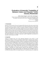
Fig. 3. Proposed dual-input serial converter
output voltage of an SC-based circuit to the voltage of solar-cells. According to the voltage of
solar-cells, the proposed converter changes the operation modes as shown in Table 2, where
V
tag
(Typ. =5 V) denotes the target output voltage ( 3V
in1
/2) to drive LEDs.
To realize the operation modes shown in Table 2, power switches S
1
∼ S
10
in figure 3 are
driven by 2-phase clock pulses, synchronously. By controlling S
1
∼ S
10
, the proposed con-
verter performs a step-up DC-DC conversion. Table 3 shows the setting of clock pulses. In
Table 3, the interval of Charging
(= State − T1) and Trans f er (= State − T2) is set to
T
= T1 + T2,
T1
= DT,
and T2
= (1 − D)T, (1)
where D and T denote the duty factor and the period of the clock pulses, respectively.
Input voltage V
in2
Conversion ration
Block-1 Block-2
Mode-1
2V
tag
3
≤ V
in2
1
2
× 1×
Mode-2
V
tag
3
≤ V
in2
<
2V
tag
3
1× 1×
Mode-3 V
in2
<
V
tag
3
3
2
× 0×
Table 2. Setting of conversion ratio
Phase On Off
Mode-1
Charging (State − T1) S
1
, S
2
, S
3
, S
4
S
5
, S
6
, S
7
, S
8
, S
9
, S
10
Transfer (State − T2) S
5
, S
6
, S
7
, S
8
S
1
, S
2
, S
3
, S
4
, S
9
, S
10
Mode-2
Charging (State − T1) S
1
, S
2
, S
3
, S
4
S
5
, S
6
, S
7
, S
8
, S
9
, S
10
Transfer (State − T2) S
2
, S
6
, S
7
S
1
, S
3
, S
4
, S
5
, S
8
, S
9
, S
10
Mode-3
Charging (State − T1) S
1
, S
2
, S
3
S
4
, S
5
, S
6
, S
7
, S
8
, S
9
, S
10
Transfer (State − T2) S
7
, S
8
, S
9
, S
10
S
1
, S
2
, S
3
, S
4
, S
5
, S
6
Table 3. Setting of clock pulses
Figure 4 shows the comparison concerning the input range of figures 2 and 3. As figure 4
shows, the proposed converter can extend the input range of V
in2
from V
in2
≥ V
tag
/2 to
V
in2
≥ V
tag
/3. Concretely, in comparison with the conventional parallel converter using 1.5×
step-up converters, the proposed converter can achieve 16% extension of input range.
Furthermore, the proposed converter can realize small hardware-cost. Table 4 shows the com-
parison concerning the hardware-cost of figures 2 and 3. As Table 4 shows, the hardware-cost
of the proposed converter is less than 80 % of that of the conventional converter.
The circuit properties of the proposed serial converter will be described in the following sec-
tion.
3. Theoretical Analysis
First, the equivalent circuit of the proposed converter is analyzed. To save space, only the
analysis for Mode-1 is described in this section
4
. In the theoretical analysis, we assume that
1. parasitic elements are negligibly small and 2. time constant is much larger than the period
of clock pulses.
Figure 5 shows instantaneous equivalent circuits of the proposed converter. In figure 5, R
on
5
denotes the on-resistance of power switches.
4
The theoretical analysis for Mode-2 and Mode-3 will be described in Appendix.
5
SC power converters are known as an implementable converter, because they do not require magnetic
elements. In the converter block implemented into a chip, the direction of fluctuation in on-resistances
is almost the same. Therefore, to simplify the theoretical analysis, we assume that all the power switches
have the same on-resistances.
Clean Energy Systems and Experiences24
Vin2
Vtag
3
Vtag
2
2
Vtag
1
0
1.5 x
mode
2 x
mode
1.5 x
mode
Conventional
Converter
Battery
operation
Solar input
operation
Mode-1
Mode-2
Mode-3
0
3
Vtag
2
Proposed
Converter
Battery
operation
Solar input
+
Battery input
operation
Vtag
3
Vtag
1
6
Vtag
1
16%
improved!
Fig. 4. Comparison concerning input range of V
in2
Number of Number of
switches capacitors
Conventional
14 5
converter
Proposed 10 4
converter (71 %) (80 %)
Table 4. Comparison concerning hardware cost
In the steady state of figure 5, differential values of the electric charges in C
k
(k = {1, 2, 3, 4})
satisfy
∆q
k
T1
+ ∆q
k
T 2
= 0, (2)
where ∆q
k
T1
and ∆q
k
T 2
denote electric charges when State − T 1 and State − T 2, respectively. In
the case of State
− T1, differential values of the electric charges in the input and the output
terminals, ∆q
T1,V
in1
, ∆q
T 1,V
in2
, and ∆q
T1,V
out
, are given by
∆q
T 1,V
in1
= ∆q
1
T 1
= ∆q
2
T 1
,
∆q
T 1,V
in2
= ∆q
3
T 1
,
and ∆q
T 1,V
out
= ∆q
4
T 1
. (3)
On the other hand, in the case of State
− T2, differential values of the electric charges in the
input and the output terminals, ∆q
T 2,V
in1
, ∆q
T 2,V
in2
, and ∆q
T 2,V
out
, are given by
∆q
T2,V
in1
= 0,
∆q
T2,V
in2
= 0,
and ∆q
T2,V
out
= ∆q
1
T2
+ ∆q
2
T2
+ ∆q
4
T2
. (4)
Vin2
C
3
C
1
C
2
Vin1
Vout
C
4
Ron
Ron
Ron
Ron
∆q
Τ1,Vin2
∆q
Τ1,Vin1
∆q
Τ1,Vout
(a) State − T1
Vin2
C
3
C
1
C
2
Vin1
Vout
C
4
∆q
Τ2,Vout
∆q
Τ2,Vin2
∆q
Τ2,Vin1
Ron
Ron
RonRon
(b) State − T2
Fig. 5. Instantaneous equivalent circuits when 2V
tag
/3 ≤ V
in2
Furthermore, in figure 5, the following condition is satisfied:
∆q
3
T 2
= ∆q
1
T2
+ ∆q
2
T2
. (5)
Here, average currents of the inputs and the output are given by
I
in1
= (∆q
T1,V
in1
+ ∆q
T 2,V
in1
)/T
≡ ∆q
V
in1
/T,
I
in2
= (∆q
T1,V
in2
+ ∆q
T 2,V
in2
)/T
≡ ∆q
V
in2
/T,
and I
out
= (∆q
T 1,V
out
+ ∆q
T2,V
out
)/T
≡ ∆q
V
out
/T, (6)
where ∆q
V
in1
, ∆q
V
in2
, and ∆q
V
out
are electric charges in the input terminal-1, the input terminal-
2, and the output terminal, respectively. From equations (2)
∼ (6), the relation between the
A dual-input DC-DC converter using clean energy power supplies 25
Vin2
Vtag
3
Vtag
2
2
V
tag
1
0
1.5 x
mode
2 x
mode
1.5 x
mode
Conventional
Converter
Battery
operation
Solar input
operation
Mode-1
Mode-2
Mode-3
0
3
V
tag
2
Proposed
Converter
Battery
operation
Solar input
+
Battery input
operation
V
tag
3
Vtag
1
6
V
tag
1
16%
improved!
Fig. 4. Comparison concerning input range of V
in2
Number of Number of
switches capacitors
Conventional
14 5
converter
Proposed 10 4
converter (71 %) (80 %)
Table 4. Comparison concerning hardware cost
In the steady state of figure 5, differential values of the electric charges in C
k
(k = {1, 2, 3, 4})
satisfy
∆q
k
T1
+ ∆q
k
T 2
= 0, (2)
where ∆q
k
T1
and ∆q
k
T 2
denote electric charges when State − T 1 and State − T 2, respectively. In
the case of State
− T1, differential values of the electric charges in the input and the output
terminals, ∆q
T1,V
in1
, ∆q
T 1,V
in2
, and ∆q
T1,V
out
, are given by
∆q
T 1,V
in1
= ∆q
1
T 1
= ∆q
2
T 1
,
∆q
T 1,V
in2
= ∆q
3
T 1
,
and ∆q
T 1,V
out
= ∆q
4
T 1
. (3)
On the other hand, in the case of State
− T2, differential values of the electric charges in the
input and the output terminals, ∆q
T 2,V
in1
, ∆q
T 2,V
in2
, and ∆q
T 2,V
out
, are given by
∆q
T2,V
in1
= 0,
∆q
T2,V
in2
= 0,
and ∆q
T2,V
out
= ∆q
1
T2
+ ∆q
2
T2
+ ∆q
4
T2
. (4)
Vin2
C
3
C
1
C
2
Vin1
Vout
C
4
Ron
Ron
Ron
Ron
∆q
Τ1,Vin2
∆q
Τ1,Vin1
∆q
Τ1,Vout
(a) State − T1
Vin2
C
3
C
1
C
2
Vin1
Vout
C
4
∆q
Τ2,Vout
∆q
Τ2,Vin2
∆q
Τ2,Vin1
Ron
Ron
RonRon
(b) State − T2
Fig. 5. Instantaneous equivalent circuits when 2V
tag
/3 ≤ V
in2
Furthermore, in figure 5, the following condition is satisfied:
∆q
3
T 2
= ∆q
1
T2
+ ∆q
2
T2
. (5)
Here, average currents of the inputs and the output are given by
I
in1
= (∆q
T1,V
in1
+ ∆q
T 2,V
in1
)/T
≡ ∆q
V
in1
/T,
I
in2
= (∆q
T1,V
in2
+ ∆q
T 2,V
in2
)/T
≡ ∆q
V
in2
/T,
and
I
out
= (∆q
T 1,V
out
+ ∆q
T2,V
out
)/T
≡ ∆q
V
out
/T, (6)
where ∆q
V
in1
, ∆q
V
in2
, and ∆q
V
out
are electric charges in the input terminal-1, the input terminal-
2, and the output terminal, respectively. From equations (2)
∼ (6), the relation between the
Clean Energy Systems and Experiences26
RSC
1 : M
Iin
Vin
RL
Vout
Iout
Fig. 6. General form of equivalent circuit
RLVout
1 : M2
Vo2
Iin2
Vin2
1 : M1
Vo1
IoutIin1
Vin1
RSC
Fig. 7. Equivalent circuit of proposed converter
input currents and the output current are derived:
I
in1
= −
1
2
I
out
and
I
in2
= −I
out
. (7)
In figure 5, the energy consumed by resistors in one period, W
T
, can be expressed as
W
T
= W
T 1
+ W
T 2
, (8)
where
W
T 1
=
3R
on
T1
(∆q
1
T1
)
2
+
R
on
T1
(∆q
3
T 1
)
2
(9)
and W
T 2
=
2R
on
T2
(∆q
1
T2
)
2
+
2R
on
T2
(∆q
2
T 2
)
2
. (10)
From equations (2)
∼ (7), equations (9) and (10) can be rewritten as
W
T1
=
7R
on
4DT
(∆q
V
out
)
2
(11)
and W
T2
=
R
on
(1 − D)T
(∆q
V
out
)
2
. (12)
Input voltage V
in2
R
SC
M1 M2
2V
tag
3
≤ V
in2
(7 − 3 D)R
on
4D(1 − D)
1
2
1
V
tag
3
≤ V
in2
<
2V
tag
3
(4 − D)R
on
D(1 − D)
1 1
V
in2
<
V
tag
3
(3 + D)R
on
4D(1 − D)
3
2
0
Table 5. Theoretical results of other conversion ratios
Here, a general equivalent circuit of SC power converters (Eguchi (2009a;b; 2010a;b)) can be
given by the circuit shown in figure 6, where R
SC
is called the SC resistance, M is the ratio of
an ideal transformer, and V
in
and V
out
denote the averaged input voltage and the averaged
output voltage, respectively. The consumed energy W
T
in figure 6 can be defined by
W
T
= W
T 1
+ W
T2
≡ (
∆q
V
out
T
)
2
· R
SC
· T. (13)
By substituting equations (11) and (12) into equation (13), SC resistance R
SC
for Mode-1 is
given by
R
SC
=
7 − 3D
4D
(1 − D)
·
R
on
. (14)
The equivalent circuit shown in figure 6 can be expressed by the determinant using
the Kettenmatrix. Therefore, by using equations (7) and (14), the equivalent circuit of the
proposed step-up converter can be given by the circuit shown in figure 7 and the following
determinants:
V
in1
I
in1
=
1/M1 0
0 M1
V
o1
I
out
, (15)
V
in2
I
in2
=
1/M2 0
0 M2
V
o2
I
out
, (16)
V
o1
+ V
o2
I
out
=
1 R
SC
0 1
V
out
−I
out
, (17)
where M1
= 1/2 and M2 = 1. To save space, only the conversion mode in the case of
2V
tag
/3 ≤ V
in2
was discussed in this section. However, other cases can also be analyzed by
the same method. Table 5 shows parameters M1, M2, and R
SC
of other modes.
By using equations (15)
∼ (17) and figure 7, power efficiency η
6
can be expressed by
η
=
R
L
(I
out
)
2
R
L
(I
out
)
2
+ R
SC
(I
out
)
2
=
R
L
R
L
+ R
SC
, (18)
6
Of course, the consumed energy of peripheral circuits such as pulse generators, comparators, etc. is
disregarded in the power efficiency of equation (18).
A dual-input DC-DC converter using clean energy power supplies 27
RSC
1 : M
I
in
Vin
RL
Vout
Iout
Fig. 6. General form of equivalent circuit
RLVout
1 : M2
Vo2
Iin2
Vin2
1 : M1
Vo1
IoutIin1
Vin1
RSC
Fig. 7. Equivalent circuit of proposed converter
input currents and the output current are derived:
I
in1
= −
1
2
I
out
and I
in2
= −I
out
. (7)
In figure 5, the energy consumed by resistors in one period, W
T
, can be expressed as
W
T
= W
T 1
+ W
T 2
, (8)
where
W
T 1
=
3R
on
T1
(∆q
1
T1
)
2
+
R
on
T1
(∆q
3
T 1
)
2
(9)
and W
T 2
=
2R
on
T2
(∆q
1
T2
)
2
+
2R
on
T2
(∆q
2
T 2
)
2
. (10)
From equations (2)
∼ (7), equations (9) and (10) can be rewritten as
W
T1
=
7R
on
4DT
(∆q
V
out
)
2
(11)
and W
T2
=
R
on
(1 − D)T
(∆q
V
out
)
2
. (12)
Input voltage V
in2
R
SC
M1 M2
2V
tag
3
≤ V
in2
(7 − 3 D)R
on
4D(1 − D)
1
2
1
V
tag
3
≤ V
in2
<
2V
tag
3
(4 − D)R
on
D(1 − D)
1 1
V
in2
<
V
tag
3
(3 + D)R
on
4D(1 − D)
3
2
0
Table 5. Theoretical results of other conversion ratios
Here, a general equivalent circuit of SC power converters (Eguchi (2009a;b; 2010a;b)) can be
given by the circuit shown in figure 6, where R
SC
is called the SC resistance, M is the ratio of
an ideal transformer, and
V
in
and V
out
denote the averaged input voltage and the averaged
output voltage, respectively. The consumed energy W
T
in figure 6 can be defined by
W
T
= W
T 1
+ W
T2
≡ (
∆q
V
out
T
)
2
· R
SC
· T. (13)
By substituting equations (11) and (12) into equation (13), SC resistance R
SC
for Mode-1 is
given by
R
SC
=
7 − 3D
4D(1 − D)
·
R
on
. (14)
The equivalent circuit shown in figure 6 can be expressed by the determinant using
the Kettenmatrix. Therefore, by using equations (7) and (14), the equivalent circuit of the
proposed step-up converter can be given by the circuit shown in figure 7 and the following
determinants:
V
in1
I
in1
=
1/M1 0
0 M1
V
o1
I
out
, (15)
V
in2
I
in2
=
1/M2 0
0 M2
V
o2
I
out
, (16)
V
o1
+ V
o2
I
out
=
1 R
SC
0 1
V
out
−I
out
, (17)
where M1
= 1/2 and M2 = 1. To save space, only the conversion mode in the case of
2V
tag
/3 ≤ V
in2
was discussed in this section. However, other cases can also be analyzed by
the same method. Table 5 shows parameters M1, M2, and R
SC
of other modes.
By using equations (15)
∼ (17) and figure 7, power efficiency η
6
can be expressed by
η
=
R
L
(I
out
)
2
R
L
(I
out
)
2
+ R
SC
(I
out
)
2
=
R
L
R
L
+ R
SC
, (18)
6
Of course, the consumed energy of peripheral circuits such as pulse generators, comparators, etc. is
disregarded in the power efficiency of equation (18).
Clean Energy Systems and Experiences28
0
1
2
3
4
5
6
0 0.1 0.2 0.3 0.4 0.5
Input Vin1, Input Vin2
Time (ms)
Voltage (V)
RL = 1 kΩ
Output Vout
Mode - 1
0
1
2
3
4
5
6
0 0.1 0.2 0.3 0.4 0.5
Input Vin2
Input Vin1
Time (ms)
Voltage (V)
RL = 1 kΩ
Output Vout
Mode - 2
(a) Mode-1 (b) Mode-2
Fig. 8. Output voltage of proposed converter
where the optimal value of parameter D is obtained when
dR
SC
dD
= 0 and 0 < D < 1. (19)
Concretely, from equations (14) and (19), the optimal duty factor is D
0.57 for Mode-1.
4. Simulation
To confirm the validity of the theoretical analysis, SPICE simulations were performed under
conditions where where V
in1
= 3.7 V, C
1
∼ C
4
= 2 µF, T = 1 µs, D = 0.5, and R
on
= 2ohm.
Figure 8 shows the output voltage of the proposed converter, where the output voltage was
not regulated. In figure 8, input voltage V
in2
for Mode-1 and Mode-2 was set to V
in2
= V
in1
and V
in2
= V
in1
/2, respectively. As figure 8 shows, in spite of the change in V
in2
, the proposed
converter can generate the stepped-up output voltage. In other words, the proposed converter
can realize wide input-range of V
in2
.
Figure 9 shows the power efficiency of the proposed converter as a function of output load R
L
.
In figure 9, input voltage V
in2
for Mode-1 and Mode-2 was set to V
in2
= V
in1
and V
in2
= V
in1
/2,
respectively. As figure 9 shows, theoretical results correspond well with simulated results.
For this reason, the derived theoretical formulas will be helpful to design the series converter.
Of course, the power efficiency can be improved by using power-switches with small on-
resistance.
5. Experiment
To confirm the validity of circuit design, experiments were performed regarding to the pro-
posed converter shown in figure 3. The experimental circuit was built with commercially
available transistors on a bread board.
Figures 10, 11, and 12 show the experimental results of the bread board circuit, where input
voltages capacitors V
in1
= 3.7 V, C
1
∼ C
4
= 3.3µF, R
L
= 10kohm, T = 100µs, and D = 0.5.
In figures 10, 11, and 12, input voltage V
in2
was set to about 3.7 V, 1.8 V, and 0V, respectively.
Output load RL (Ω)
Power efficiency (%)
0
10
20
30
40
50
60
70
80
90
100
1 10 100 1000
Simulated (Mode-2)
Simulated (Mode-3)
Simulated (Mode-1)
Theoretical (Mode-2)
Theoretical (Mode-3)
Theoretical (Mode-1)
Fig. 9. Power efficiency as function of output load R
L
Avg. Vout = 5.21V
V
in1
GND of CH2
GND of CH1
Mode-1
V
out
Avg. Vout = 5.20V
V
in2
GND of CH2
GND of CH1
Mode-1
V
out
(a) V
out
vs. V
in1
(b) V
out
vs. V
in2
Fig. 10. Measured output voltages for Mode-1
As these figures show, the circuit design of the proposed converter is appropriate, because the
stepped-up voltage about 5 V can be generated
7
.
6. Conclusion
In this chapter, a serial SC DC-DC converter using clean energy power supplies has been
proposed.
The validity of the circuit design was confirmed by theoretical analyses, SPICE simulations,
and experiments. The proposed converter can realize not only long battery runtime but also
small hardware-cost and wide input-range. Concretely, in comparison with the conventional
parallel converter using 1.5
× step-up SC converters, the proposed converter can achieve 20%
7
In the experiment, the circuit properties such as power efficiency, ripple noise, etc. were not examined,
because the experimental circuit was built with commercially available transistors on the bread board.
Only the circuit design was verified through the experiments, because the parasitic resistance of the
bread board is very large unlike an IC chip.
A dual-input DC-DC converter using clean energy power supplies 29
0
1
2
3
4
5
6
0 0.1 0.2 0.3 0.4 0.5
Input Vin1, Input Vin2
Time (ms)
Voltage (V)
RL = 1 kΩ
Output V
out
Mode - 1
0
1
2
3
4
5
6
0 0.1 0.2 0.3 0.4 0.5
Input Vin2
Input Vin1
Time (ms)
Voltage (V)
RL = 1 kΩ
Output V
out
Mode - 2
(a) Mode-1 (b) Mode-2
Fig. 8. Output voltage of proposed converter
where the optimal value of parameter D is obtained when
dR
SC
dD
= 0 and 0 < D < 1. (19)
Concretely, from equations (14) and (19), the optimal duty factor is D
0.57 for Mode-1.
4. Simulation
To confirm the validity of the theoretical analysis, SPICE simulations were performed under
conditions where where V
in1
= 3.7 V, C
1
∼ C
4
= 2 µF, T = 1 µs, D = 0.5, and R
on
= 2ohm.
Figure 8 shows the output voltage of the proposed converter, where the output voltage was
not regulated. In figure 8, input voltage V
in2
for Mode-1 and Mode-2 was set to V
in2
= V
in1
and V
in2
= V
in1
/2, respectively. As figure 8 shows, in spite of the change in V
in2
, the proposed
converter can generate the stepped-up output voltage. In other words, the proposed converter
can realize wide input-range of V
in2
.
Figure 9 shows the power efficiency of the proposed converter as a function of output load R
L
.
In figure 9, input voltage V
in2
for Mode-1 and Mode-2 was set to V
in2
= V
in1
and V
in2
= V
in1
/2,
respectively. As figure 9 shows, theoretical results correspond well with simulated results.
For this reason, the derived theoretical formulas will be helpful to design the series converter.
Of course, the power efficiency can be improved by using power-switches with small on-
resistance.
5. Experiment
To confirm the validity of circuit design, experiments were performed regarding to the pro-
posed converter shown in figure 3. The experimental circuit was built with commercially
available transistors on a bread board.
Figures 10, 11, and 12 show the experimental results of the bread board circuit, where input
voltages capacitors V
in1
= 3.7 V, C
1
∼ C
4
= 3.3µF, R
L
= 10kohm, T = 100µs, and D = 0.5.
In figures 10, 11, and 12, input voltage V
in2
was set to about 3.7 V, 1.8 V, and 0V, respectively.
Output load RL (Ω)
Power efficiency (%)
0
10
20
30
40
50
60
70
80
90
100
1 10 100 1000
Simulated (Mode-2)
Simulated (Mode-3)
Simulated (Mode-1)
Theoretical (Mode-2)
Theoretical (Mode-3)
Theoretical (Mode-1)
Fig. 9. Power efficiency as function of output load R
L
Avg. Vout = 5.21V
Vin1
GND of CH2
GND of CH1
Mode-1
Vout
Avg. Vout = 5.20V
Vin2
GND of CH2
GND of CH1
Mode-1
Vout
(a) V
out
vs. V
in1
(b) V
out
vs. V
in2
Fig. 10. Measured output voltages for Mode-1
As these figures show, the circuit design of the proposed converter is appropriate, because the
stepped-up voltage about 5 V can be generated
7
.
6. Conclusion
In this chapter, a serial SC DC-DC converter using clean energy power supplies has been
proposed.
The validity of the circuit design was confirmed by theoretical analyses, SPICE simulations,
and experiments. The proposed converter can realize not only long battery runtime but also
small hardware-cost and wide input-range. Concretely, in comparison with the conventional
parallel converter using 1.5
× step-up SC converters, the proposed converter can achieve 20%
7
In the experiment, the circuit properties such as power efficiency, ripple noise, etc. were not examined,
because the experimental circuit was built with commercially available transistors on the bread board.
Only the circuit design was verified through the experiments, because the parasitic resistance of the
bread board is very large unlike an IC chip.
Clean Energy Systems and Experiences30
Avg. Vout = 5.11V
Vin1
GND of CH2
Mode-2
GND of CH1
Vout
Avg. Vout = 5.12V
Vin2
GND of CH2
GND of CH1
Mode-2
Vout
(a) V
out
vs. V
in1
(b) V
out
vs. V
in2
Fig. 11. Measured output voltages for Mode-2
Avg. Vout = 5.14V
Vin1
GND of CH2
Mode-3
GND of CH1
Vout
Avg. Vout = 5.13V
Vin2
GND of CH2
Mode-3
GND of CH1
Vout
(a) V
out
vs. V
in1
(b) V
out
vs. V
in2
Fig. 12. Measured output voltages for Mode-3
reduction of hardware cost and 16% extension of input range. Furthermore, the derived theo-
retical formulas can provide basic information to design serial SC DC-DC converters, because
theoretical results corresponded well with SPICE simulation results. The proposed converter
will be useful as a driver circuit of white LEDs for display back-lighting.
The IC implementation and experiments are left to a future study.
Appendix
Theoretical analysis for Mode-2
In this section, the characteristics of the proposed converter for V
tag
/3 ≤ V
in2
< 2V
tag
/3 is
analyzed theoretically. The conditions of this theoretical analysis are the same as that shown
in section 3.
Figure 13 shows the instantaneous equivalent circuits for Mode-2. In the steady state, the
differential value of electric charges in C
k
(k = {1, 2,3,4}) satisfies equation (2). In the case
of State
− T1, differential values of electric charges in the input terminals and the output
Vin2
C
3
C
1
C
2
Vin1
Vout
C
4
Ron
Ron
Ron
Ron
∆q
Τ1,Vin2
∆q
Τ1,Vin1
∆q
Τ1,Vout
(a) State − T1
Vin2
C
3
C
1
C
2
Vin1
Vout
C
4
Ron
Ron
Ron
∆q
Τ2,Vout
∆q
Τ2,Vin1
∆q
Τ2,Vin2
(b) State − T2
Fig. 13. Instantaneous equivalent circuits when V
tag
/3 ≤ V
in2
< 2V
tag
/3
terminal, ∆q
T1,V
in1
, ∆q
T1,V
in2
, and ∆q
T1,V
out
, are given by
∆q
T1,V
in1
= ∆q
1
T1
− ∆q
2
T 1
,
∆q
T1,V
in2
= ∆q
3
T1
,
and ∆q
T1,V
out
= ∆q
4
T1
. (20)
In the case of State
− T 2, differential values of electric charges in the input terminals and the
output terminal, ∆q
T2,V
in1
, ∆q
T2,V
in2
, and ∆q
T2,V
out
, are given by
∆q
T 2,V
in1
= 0,
∆q
T 2,V
in2
= 0,
and ∆q
T 2,V
out
= ∆q
1
T 2
+ ∆q
4
T 2
= ∆q
2
T 2
+ ∆q
4
T 2
= ∆q
3
T2
+ ∆q
4
T2
. (21)
A dual-input DC-DC converter using clean energy power supplies 31
Avg. Vout = 5.11V
V
in1
GND of CH2
Mode-2
GND of CH1
Vout
Avg. Vout = 5.12V
V
in2
GND of CH2
GND of CH1
Mode-2
Vout
(a) V
out
vs. V
in1
(b) V
out
vs. V
in2
Fig. 11. Measured output voltages for Mode-2
Avg. Vout = 5.14V
V
in1
GND of CH2
Mode-3
GND of CH1
Vout
Avg. Vout = 5.13V
V
in2
GND of CH2
Mode-3
GND of CH1
Vout
(a) V
out
vs. V
in1
(b) V
out
vs. V
in2
Fig. 12. Measured output voltages for Mode-3
reduction of hardware cost and 16% extension of input range. Furthermore, the derived theo-
retical formulas can provide basic information to design serial SC DC-DC converters, because
theoretical results corresponded well with SPICE simulation results. The proposed converter
will be useful as a driver circuit of white LEDs for display back-lighting.
The IC implementation and experiments are left to a future study.
Appendix
Theoretical analysis for Mode-2
In this section, the characteristics of the proposed converter for V
tag
/3 ≤ V
in2
< 2V
tag
/3 is
analyzed theoretically. The conditions of this theoretical analysis are the same as that shown
in section 3.
Figure 13 shows the instantaneous equivalent circuits for Mode-2. In the steady state, the
differential value of electric charges in C
k
(k = {1, 2,3, 4}) satisfies equation (2). In the case
of State
− T1, differential values of electric charges in the input terminals and the output
Vin2
C
3
C
1
C
2
Vin1
Vout
C
4
Ron
Ron
Ron
Ron
∆q
Τ1,Vin2
∆q
Τ1,Vin1
∆q
Τ1,Vout
(a) State − T1
Vin2
C
3
C
1
C
2
Vin1
Vout
C
4
Ron
Ron
Ron
∆q
Τ2,Vout
∆q
Τ2,Vin1
∆q
Τ2,Vin2
(b) State − T2
Fig. 13. Instantaneous equivalent circuits when V
tag
/3 ≤ V
in2
< 2V
tag
/3
terminal, ∆q
T1,V
in1
, ∆q
T1,V
in2
, and ∆q
T1,V
out
, are given by
∆q
T1,V
in1
= ∆q
1
T1
− ∆q
2
T 1
,
∆q
T1,V
in2
= ∆q
3
T1
,
and ∆q
T1,V
out
= ∆q
4
T1
. (20)
In the case of State
− T 2, differential values of electric charges in the input terminals and the
output terminal, ∆q
T2,V
in1
, ∆q
T2,V
in2
, and ∆q
T2,V
out
, are given by
∆q
T 2,V
in1
= 0,
∆q
T 2,V
in2
= 0,
and ∆q
T 2,V
out
= ∆q
1
T 2
+ ∆q
4
T 2
= ∆q
2
T 2
+ ∆q
4
T 2
= ∆q
3
T2
+ ∆q
4
T2
. (21)
Clean Energy Systems and Experiences32
By substituting equations (2), (20), and (21) into equation (6), the following equations are
derived:
I
in1
= −I
out
and I
in2
= −I
out
. (22)
In figure 13, the energy consumed by resistors in one period, W
T
, can be expressed as
W
T
= W
T 1
+ W
T 2
, (23)
where
W
T1
=
3R
on
T
1
(∆q
1
T 1
)
2
+
R
on
T
1
(∆q
3
T1
)
2
and W
T2
=
3R
on
T
2
(∆q
1
T 2
)
2
.
From equations (2), (20), and (21), equation (23) can be rewritten as
W
T
=
4R
on
DT
(∆q
V
out
)
2
+
3R
on
(1 − D)T
(∆q
V
out
)
2
. (24)
Thus, from equations (13) and (24), the SC resistance R
SC
is given by
R
SC
=
(
4 − D)R
on
D(1 − D)
. (25)
Therefore, by using equations (22) and (25), the equivalent circuit can be expressed by the
circuit shown in figure 7 and equations (15)
∼ (17), where M1 = 1 and M2 = 1. The power
efficiency can also be obtained by equation (18), where the optimal duty factor is D
0.67
when V
tag
/3 ≤ V
in2
< 2V
tag
/3.
Theoretical analysis for Mode-3
Next, the characteristics of the proposed converter for 2V
tag
/3 ≤ V
in2
is analyzed theoretically.
Figure 14 shows the instantaneous equivalent circuits when Mode-3. In the steady state, the
differential value of electric charges in C
k
(k = { 1, 2, 3, 4}) satisfies equation (2). In the case of
State
− T1, ∆q
T 1,V
in1
, ∆q
T 1,V
in2
, and ∆q
T1,V
out
, are given by
∆q
T1,V
in1
= ∆q
1
T 1
= ∆q
2
T1
,
∆q
T1,V
in2
= 0,
and ∆q
T1,V
out
= ∆q
4
T1
. (26)
On the other hand, in the case of State
− T2, ∆q
T2,V
in1
, ∆q
T 2,V
in2
, and ∆q
T2,V
out
, are given by
∆q
T 2,V
in1
= −∆q
2
T1
− ∆q
2
T2
,
∆q
T 2,V
in2
= 0,
and ∆q
T 2,V
out
= ∆q
1
T 2
+ ∆q
2
T 2
+ ∆q
4
T 2
. (27)
By substituting equations (2), (26), and (27) into equation (6), the following equation is de-
rived:
I
in1
= −
3
2
I
out
and I
in2
= 0. (28)
Vin2
C
3
C
1
C
2
Vin1
Vout
C
4
Ron
Ron
Ron
∆q
Τ1,Vin2
∆q
Τ1,Vin1
∆q
Τ1,Vout
(a) State − T1
Vin2
C
3
C
1
C
2
Vin1
Vout
C
4
∆q
Τ2,Vin1
∆q
Τ2,Vin2
Ron
Ron
Ron
Ron
(b) State − T2
Fig. 14. Instantaneous equivalent circuits when 2V
tag
/3 ≤ V
in2
In figure 14, the energy consumed by resistors in one period, W
T
, can be expressed as
W
T
= W
T 1
+ W
T 2
, (29)
where
W
T 1
=
3R
on
T
1
(∆q
1
T1
)
2
and W
T 2
=
2R
on
T
2
(∆q
1
T2
)
2
+
2R
on
T
2
(∆q
2
T2
)
2
.
From equations (2), (26), and (27), equation (29) can be rewritten as
W
T
=
3R
on
4DT
(∆q
V
out
)
2
+
R
on
(1 − D)T
(∆q
V
out
)
2
. (30)
A dual-input DC-DC converter using clean energy power supplies 33
By substituting equations (2), (20), and (21) into equation (6), the following equations are
derived:
I
in1
= −I
out
and I
in2
= −I
out
. (22)
In figure 13, the energy consumed by resistors in one period, W
T
, can be expressed as
W
T
= W
T 1
+ W
T 2
, (23)
where
W
T1
=
3R
on
T
1
(∆q
1
T 1
)
2
+
R
on
T
1
(∆q
3
T1
)
2
and W
T2
=
3R
on
T
2
(∆q
1
T 2
)
2
.
From equations (2), (20), and (21), equation (23) can be rewritten as
W
T
=
4R
on
DT
(∆q
V
out
)
2
+
3R
on
(1 − D)T
(∆q
V
out
)
2
. (24)
Thus, from equations (13) and (24), the SC resistance R
SC
is given by
R
SC
=
(
4 − D)R
on
D(1 − D)
. (25)
Therefore, by using equations (22) and (25), the equivalent circuit can be expressed by the
circuit shown in figure 7 and equations (15)
∼ (17), where M1 = 1 and M2 = 1. The power
efficiency can also be obtained by equation (18), where the optimal duty factor is D
0.67
when V
tag
/3 ≤ V
in2
< 2V
tag
/3.
Theoretical analysis for Mode-3
Next, the characteristics of the proposed converter for 2V
tag
/3 ≤ V
in2
is analyzed theoretically.
Figure 14 shows the instantaneous equivalent circuits when Mode-3. In the steady state, the
differential value of electric charges in C
k
(k = { 1, 2, 3, 4}) satisfies equation (2). In the case of
State
− T1, ∆q
T 1,V
in1
, ∆q
T 1,V
in2
, and ∆q
T1,V
out
, are given by
∆q
T1,V
in1
= ∆q
1
T 1
= ∆q
2
T1
,
∆q
T1,V
in2
= 0,
and ∆q
T1,V
out
= ∆q
4
T1
. (26)
On the other hand, in the case of State
− T2, ∆q
T2,V
in1
, ∆q
T 2,V
in2
, and ∆q
T2,V
out
, are given by
∆q
T 2,V
in1
= −∆q
2
T1
− ∆q
2
T2
,
∆q
T 2,V
in2
= 0,
and ∆q
T 2,V
out
= ∆q
1
T 2
+ ∆q
2
T 2
+ ∆q
4
T 2
. (27)
By substituting equations (2), (26), and (27) into equation (6), the following equation is de-
rived:
I
in1
= −
3
2
I
out
and I
in2
= 0. (28)
Vin2
C
3
C
1
C
2
Vin1
Vout
C
4
Ron
Ron
Ron
∆q
Τ1,Vin2
∆q
Τ1,Vin1
∆q
Τ1,Vout
(a) State − T1
Vin2
C
3
C
1
C
2
Vin1
Vout
C
4
∆q
Τ2,Vin1
∆q
Τ2,Vin2
Ron
Ron
Ron
Ron
(b) State − T2
Fig. 14. Instantaneous equivalent circuits when 2V
tag
/3 ≤ V
in2
In figure 14, the energy consumed by resistors in one period, W
T
, can be expressed as
W
T
= W
T 1
+ W
T 2
, (29)
where
W
T 1
=
3R
on
T
1
(∆q
1
T1
)
2
and W
T 2
=
2R
on
T
2
(∆q
1
T2
)
2
+
2R
on
T
2
(∆q
2
T2
)
2
.
From equations (2), (26), and (27), equation (29) can be rewritten as
W
T
=
3R
on
4DT
(∆q
V
out
)
2
+
R
on
(1 − D)T
(∆q
V
out
)
2
. (30)
Clean Energy Systems and Experiences34
Thus, from equations (13) and (30), the SC resistance R
SC
is given by
R
SC
=
(
3 + D)R
on
4D(1 − D)
. (31)
Therefore, by using equations (28) and (31), the equivalent circuit can be expressed by the
circuit shown in figure 7 and equations (15)
∼ (17), where M1 = 3/2 and M2 = 0. The power
efficiency can also be obtained by equation (18), where the optimal duty factor is D
0.46
when 2V
tag
/3 ≤ V
in2
.
7. References
Bong, J.H.; Kwon, Y.J.; Kim, D. & Min,K.S. (2009). Negative charge pump circuit with large
output current and high power efficiency. IEICE Electronics EXpress, Vol.6 (No.6): 304-
309. ISSN 1349-2543
Chung, I.Y. & Shin, J. (2009). New charge pump circuits for high output voltage and large
current drivability. IEICE Electronics EXpress, Vol.6 (No.12): 800-805. ISSN 1349-2543
Doms, I.; Merken, P.; Hoof, C.V. & Mertens, R.P. (2009). Capacitive power management circuit
for micropower thermoelectric generators with a 1.4µA controller. IEEE, J. Solid-State
Circuits, Vol.44 (No.10): 2824-2833. ISSN 0018-9200
Eguchi, K.; Oota, I.; Terada, S. & Inoue, T. (2009). A design method of switched-capacitor
power converters by employing a ring-type power converter. Int. J. of Innovative Com-
puting, Information and Control, Vol.5 (No.10 (A)): 2927-2938. ISSN 1349-4198
Eguchi, K.; Pongswatd, S.; Tirasesth, K. & Sasaki, H. (2009). Synthesis and analysis of a
multiple-input parallel SC DC-DC converter. Proceedings of the 2009 ECTI International
Conference, pp.306-309, ISBN 978-1-4244-3388-9, Thailand, May 2009, the Institute of
Electrical and Electronics Engineers, Piscataway
Eguchi, K.; Pongswatd, S.; Tirasesth, K.; Sasaki, H. & Inoue, T. (2010). Optimal design of a
single-input parallel DC-DC converter designed by switched capacitor techniques.
Int. J. of Innovative Computing, Information and Control, Vol.6 (No.1 (A)): 215-227. ISSN
1349-4198
Eguchi, K.; Pongswatd, S.; Julsereewong, A.; Tirasesth, K.; Sasaki, H. & Inoue, T. (2010). De-
sign of a multiple-input SC DC-DC converter realizing long battery runtime. IEICE,
Fundamentals, Vol.E93-A (No.5): 985-988. ISSN 1745-1337
Gregoire, B.R. (2006). A compact switched-capacitor regulated charge pump power supply.
IEEE, J. Solid-State Circuits, Vol.41 (No.8): 1944-1953. ISSN 0018-9200
Ishikawa, Y. & Saito, T. (2007). Synchronization and chaos in multiple-input parallel DC-DC
converters with WTA switching. IEICE, Fundamentals, Vol.E90-A (No.6): 1162-1169.
ISSN 1745-1337
Kabe, T.; Parui, S.; Torikai, H.; Banerjee, S. & Saito, T. (2007). Analysis of current mode
controlled DC-DC converters through piecewise linear models. IEICE, Fundamentals,
Vol.E90-A (No.2): 448-456. ISSN 1745-1337
Min, K. & Ahn, J. (2002). CMOS charge pumps using cross-coupled charge transfer switches
with improved voltage pumping gain and low gate-oxide stress for low-voltage
memory circuits. IEICE, Electronics, Vol.E85-C (No.1): 225-229. ISSN 1745-1353
Myono, T.; Uemoto, A.; Kawai, S.; Nishibe, E.; Kikuchi, S.; Iijima, T. & Kobayashi,H. (2001).
High-efficiency charge-pump circuits with large current output for mobile equip-
ment applications. IEICE, Electronics, Vol.E84-C (No.10): 1602-1611. ISSN 1745-1353
Pan, J.; Inoue, Y. & Liang, Z. (2007) An energy management circuit for self-powered ubiqui-
tous sensor modules using vibration-based energy, IEICE, Fundamentals, Vol.E90-A
(No.10): 2116-2123. ISSN 1745-1337
Park, S.J.; Kang, Y.G.; Kim, J.Y.; Han, T.H.; Jun, Y.H.; Lee, C. & Kong, B.S. (2009). CMOS cross-
coupled charge pump with improved latch-up immunity. IEICE Electronics EXpress,
Vol.6 (No.11): 736-742. ISSN 1349-2543
Qiu, Y.; Xu, M.; Yao, K.; Sun, J. & Lee, F.C. (2006). Multifrequency small signal model for buck
and multiphase buck converters. IEEE, Power Electronics, Vol.21 (No.5): 1185-1192.
ISSN 0885-8993
Starzyk, J.A.; Jan, T.W. & Qiu, F. (2001). A DC-DC charge pump design based on voltage
doublers. IEEE Trans. Circuit & Syst I, Vol.48 (No.3): 350-359. ISSN 1057-7122
Tanzawa, T. & Tanaka, T. (1997). A dynamic analysis of the Dickson charge pump circuit. IEEE,
J. Solid-State Circuits, Vol.32 (No.8): 1237-1240. ISSN 0018-9200
Wei, C.L.; Wu, L.Y.; Yang, H.H.; Tsai, C.H.; Liu,B.D. & Chang, S.J. (2008). A versatile
step-up/step-down switched-capacitor-based DC-DC converter, IEICE, Electronics,
Vol.E91-C (No.5): 809-812. ISSN 1745-1353
Yamada, K.; Fujii, N. & Takagi, S. (2004). Capacitance value free switched capacitor DC-DC
voltage converter realizing arbitrary rational conversion ratio. IEICE, Fundamentals,
Vol.E87-A (No.2): 344-349. ISSN 1745-1337
Yamakawa, T.; Inoue, T. & Tsuneda, A. (2008). Design and experiments of a novel low-ripple
Cockcroft-Walton AC-to-DC converter for a coil-coupled passive RFID tag. IEICE,
Fundamentals, Vol.E91-A (No.2): 513-520. ISSN 1745-1337
A dual-input DC-DC converter using clean energy power supplies 35
Thus, from equations (13) and (30), the SC resistance R
SC
is given by
R
SC
=
(
3 + D)R
on
4D(1 − D)
. (31)
Therefore, by using equations (28) and (31), the equivalent circuit can be expressed by the
circuit shown in figure 7 and equations (15)
∼ (17), where M1 = 3/2 and M2 = 0. The power
efficiency can also be obtained by equation (18), where the optimal duty factor is D
0.46
when 2V
tag
/3 ≤ V
in2
.
7. References
Bong, J.H.; Kwon, Y.J.; Kim, D. & Min,K.S. (2009). Negative charge pump circuit with large
output current and high power efficiency. IEICE Electronics EXpress, Vol.6 (No.6): 304-
309. ISSN 1349-2543
Chung, I.Y. & Shin, J. (2009). New charge pump circuits for high output voltage and large
current drivability. IEICE Electronics EXpress, Vol.6 (No.12): 800-805. ISSN 1349-2543
Doms, I.; Merken, P.; Hoof, C.V. & Mertens, R.P. (2009). Capacitive power management circuit
for micropower thermoelectric generators with a 1.4µA controller. IEEE, J. Solid-State
Circuits, Vol.44 (No.10): 2824-2833. ISSN 0018-9200
Eguchi, K.; Oota, I.; Terada, S. & Inoue, T. (2009). A design method of switched-capacitor
power converters by employing a ring-type power converter. Int. J. of Innovative Com-
puting, Information and Control, Vol.5 (No.10 (A)): 2927-2938. ISSN 1349-4198
Eguchi, K.; Pongswatd, S.; Tirasesth, K. & Sasaki, H. (2009). Synthesis and analysis of a
multiple-input parallel SC DC-DC converter. Proceedings of the 2009 ECTI International
Conference, pp.306-309, ISBN 978-1-4244-3388-9, Thailand, May 2009, the Institute of
Electrical and Electronics Engineers, Piscataway
Eguchi, K.; Pongswatd, S.; Tirasesth, K.; Sasaki, H. & Inoue, T. (2010). Optimal design of a
single-input parallel DC-DC converter designed by switched capacitor techniques.
Int. J. of Innovative Computing, Information and Control, Vol.6 (No.1 (A)): 215-227. ISSN
1349-4198
Eguchi, K.; Pongswatd, S.; Julsereewong, A.; Tirasesth, K.; Sasaki, H. & Inoue, T. (2010). De-
sign of a multiple-input SC DC-DC converter realizing long battery runtime. IEICE,
Fundamentals, Vol.E93-A (No.5): 985-988. ISSN 1745-1337
Gregoire, B.R. (2006). A compact switched-capacitor regulated charge pump power supply.
IEEE, J. Solid-State Circuits, Vol.41 (No.8): 1944-1953. ISSN 0018-9200
Ishikawa, Y. & Saito, T. (2007). Synchronization and chaos in multiple-input parallel DC-DC
converters with WTA switching. IEICE, Fundamentals, Vol.E90-A (No.6): 1162-1169.
ISSN 1745-1337
Kabe, T.; Parui, S.; Torikai, H.; Banerjee, S. & Saito, T. (2007). Analysis of current mode
controlled DC-DC converters through piecewise linear models. IEICE, Fundamentals,
Vol.E90-A (No.2): 448-456. ISSN 1745-1337
Min, K. & Ahn, J. (2002). CMOS charge pumps using cross-coupled charge transfer switches
with improved voltage pumping gain and low gate-oxide stress for low-voltage
memory circuits. IEICE, Electronics, Vol.E85-C (No.1): 225-229. ISSN 1745-1353
Myono, T.; Uemoto, A.; Kawai, S.; Nishibe, E.; Kikuchi, S.; Iijima, T. & Kobayashi,H. (2001).
High-efficiency charge-pump circuits with large current output for mobile equip-
ment applications. IEICE, Electronics, Vol.E84-C (No.10): 1602-1611. ISSN 1745-1353
Pan, J.; Inoue, Y. & Liang, Z. (2007) An energy management circuit for self-powered ubiqui-
tous sensor modules using vibration-based energy, IEICE, Fundamentals, Vol.E90-A
(No.10): 2116-2123. ISSN 1745-1337
Park, S.J.; Kang, Y.G.; Kim, J.Y.; Han, T.H.; Jun, Y.H.; Lee, C. & Kong, B.S. (2009). CMOS cross-
coupled charge pump with improved latch-up immunity. IEICE Electronics EXpress,
Vol.6 (No.11): 736-742. ISSN 1349-2543
Qiu, Y.; Xu, M.; Yao, K.; Sun, J. & Lee, F.C. (2006). Multifrequency small signal model for buck
and multiphase buck converters. IEEE, Power Electronics, Vol.21 (No.5): 1185-1192.
ISSN 0885-8993
Starzyk, J.A.; Jan, T.W. & Qiu, F. (2001). A DC-DC charge pump design based on voltage
doublers. IEEE Trans. Circuit & Syst I, Vol.48 (No.3): 350-359. ISSN 1057-7122
Tanzawa, T. & Tanaka, T. (1997). A dynamic analysis of the Dickson charge pump circuit. IEEE,
J. Solid-State Circuits, Vol.32 (No.8): 1237-1240. ISSN 0018-9200
Wei, C.L.; Wu, L.Y.; Yang, H.H.; Tsai, C.H.; Liu,B.D. & Chang, S.J. (2008). A versatile
step-up/step-down switched-capacitor-based DC-DC converter, IEICE, Electronics,
Vol.E91-C (No.5): 809-812. ISSN 1745-1353
Yamada, K.; Fujii, N. & Takagi, S. (2004). Capacitance value free switched capacitor DC-DC
voltage converter realizing arbitrary rational conversion ratio. IEICE, Fundamentals,
Vol.E87-A (No.2): 344-349. ISSN 1745-1337
Yamakawa, T.; Inoue, T. & Tsuneda, A. (2008). Design and experiments of a novel low-ripple
Cockcroft-Walton AC-to-DC converter for a coil-coupled passive RFID tag. IEICE,
Fundamentals, Vol.E91-A (No.2): 513-520. ISSN 1745-1337
Clean Energy Systems and Experiences36
Development of sustainable energy research and applications 37
Development of sustainable energy research and applications
Abdeen Mustafa Omer
X
Development of sustainable
energy research and applications
Abdeen Mustafa Omer
Energy Research Institute (ERI), Sudan
Abstract
People relay upon oil for primary energy and this for a few more decades. Other orthodox
sources may be more enduring, but are not without serious disadvantages. Power from
natural resources has always had great appeal. Coal is plentiful, though there is concern
about despoliation in winning it and pollution in burning it. Nuclear power has been
developed with remarkable timeliness, but is not universally welcomed, construction of the
plant is energy-intensive and there is concern about the disposal of its long-lived active
wastes. Barrels of oil, lumps of coal, even uranium come from nature but the possibilities of
almost limitless power from the atmosphere and the oceans seem to have special attraction.
The wind machine provided an early way of developing motive power. The massive
increases in fuel prices over the last years have however, made any scheme not requiring
fuel appear to be more attractive and to be worth reinvestigation. In considering the
atmosphere and the oceans as energy sources the four main contenders are wind power,
wave power, tidal and power from ocean thermal gradients. The renewable energy
resources are particularly suited for the provision of rural power supplies and a major
advantage is that equipment such as flat plate solar driers, wind machines, etc., can be
constructed using local resources and without the advantage results from the feasibility of
local maintenance and the general encouragement such local manufacture gives to the build
up of small-scale rural based industry. This article gives some examples of small-scale
energy converters, nevertheless it should be noted that small conventional, i.e., engines are
currently the major source of power in rural areas and will continue to be so for a long time
to come. There is a need for some further development to suit local conditions, to minimise
spares holdings, to maximise interchangeability both of engine parts and of the engine
application. Emphasis should be placed on full local manufacture.
Keywords: Renewable energy technologies, energy efficiency, sustainable development,
emissions, environment.
Introduction
This chapter comprises a comprehensive review of energy sources, the environment and
sustainable development. It includes the renewable energy technologies, energy efficiency
3