Magnetic Bearings Theory and Applications Part 1 potx
Bạn đang xem bản rút gọn của tài liệu. Xem và tải ngay bản đầy đủ của tài liệu tại đây (429.22 KB, 14 trang )
Magnetic Bearings,
Theory and Applications
edited by
Boštjan Polajžer
SCIYO
Magnetic Bearings, Theory and Applications
Edited by Boštjan Polajžer
Published by Sciyo
Janeza Trdine 9, 51000 Rijeka, Croatia
Copyright © 2010 Sciyo
All chapters are Open Access articles distributed under the Creative Commons Non Commercial Share
Alike Attribution 3.0 license, which permits to copy, distribute, transmit, and adapt the work in any
medium, so long as the original work is properly cited. After this work has been published by Sciyo,
authors have the right to republish it, in whole or part, in any publication of which they are the author,
and to make other personal use of the work. Any republication, referencing or personal use of the work
must explicitly identify the original source.
Statements and opinions expressed in the chapters are these of the individual contributors and
not necessarily those of the editors or publisher. No responsibility is accepted for the accuracy of
information contained in the published articles. The publisher assumes no responsibility for any
damage or injury to persons or property arising out of the use of any materials, instructions, methods
or ideas contained in the book.
Publishing Process Manager Ana Nikolic
Technical Editor Martina Peric
Cover Designer Martina Sirotic
Image Copyright Sergey Shlyaev, 2010. Used under license from Shutterstock.com
First published October 2010
Printed in India
A free online edition of this book is available at www.sciyo.com
Additional hard copies can be obtained from
Magnetic Bearings, Theory and Applications, Edited by Boštjan Polajžer
p. cm.
ISBN 978-953-307-148-0
SCIYO.COM
WHERE KNOWLEDGE IS FREE
free online editions of Sciyo
Books, Journals and Videos can
be found at www.sciyo.com
Chapter 1
Chapter 2
Chapter 3
Chapter 4
Chapter 5
Chapter 6
Preface VII
Design and implementation of conventional
and advanced controllers for magnetic bearing system stabilization 1
Juan Shi and Wee Sit Lee
Linearization of radial force characteristic of active magnetic
bearings using finite element method and differential evolution 27
Boštjan Polajžer, Gorazd Štumberger, Jože Ritonja and Drago Dolinar
Magnetic levitation technique for active vibration control 41
Md. Emdadul Hoque and Takeshi Mizuno
Salient pole permanent magnet axial-gap self-bearing motor 61
Quang-Dich Nguyen and Satoshi Ueno
Passive permanent magnet bearings
for rotating shaft : Analytical calculation 85
Valerie Lemarquand and Guy Lemarquand
A rotor model with two gradient static
field shafts and a bulk twined heads system 117
Hitoshi Ozaku
Contents
The term magnetic bearing refers to devices that provide stable suspension of a rotor. Because
of the contact-less motion of the rotor, magnetic bearings offer many advantages for various
applications. Commercial applications include compressors, centrifuges, high-speed turbines,
energy-storage ywheels, high-precision machine tools, etc.
Magnetic bearings are a typical mechatronic product. Thus, a great deal of knowledge is
necessary for its design, construction and operation. This book is a collection of writings on
magnetic bearings, presented in fragments and divided into six chapters.
First two chapters discuss the so called “classical” magnetic bearing systems, which are
composed of two radial active magnetic bearings, one axial bearing, and an independent
driving motor. In Chapter 1, different control design approaches are applied to an
experimental magnetic bearing system MBC500. The proposed interpolation design approach
and fuzzy logic design are compared with the classical control design. Chapter 2 deals with
non-linearities of magnetic bearing radial force characteristic. The optimisation of the bearing
geometry is proposed, where the aim is to nd such design, where a radial force characteristic
is linear, as much as possible, over the entire operating range.
The following chapters present special magnetic suspension systems. Chapter 3 discusses
magnetic suspension for vibration insulation systems, where a novel zero-power control
is proposed. Self-bearing motors are discussed in Chapter 4. A structure of axial-gap self-
bearing motor is studied, whereas a vector control is discussed in details. Chapter 5 presents
different structures of passive permanent magnet bearings. Analytical formulations are given
for each case of axial, radial or perpendicular polarisation of permanent magnets. In Chapter
6, an experimental rotor model is presented with two gradient static eld shafts and a high-
temperature superconducting bulk.
Hopefully, this book will provide not only an introduction but also a number of key aspects
of magnetic bearings theory and applications. Last but not least, the presented content is free,
which is of great importance, especially for young researchers and engineers in the eld.
Editor
Boštjan Polajžer
University of Maribor, Faculty of Electrical Engineering and Computer Science
Slovenia
Preface
Design and implementation of conventional
and advanced controllers for magnetic bearing system stabilization 1
Design and implementation of conventional and advanced controllers for
magnetic bearing system stabilization
Juan Shi and Wee Sit Lee
X
Design and implementation of conventional and
advanced controllers for magnetic bearing
system stabilization
Juan Shi and Wee Sit Lee
School of Engineering and Science, Victoria University
Australia
1. Introduction
Active magnetic bearings (AMBs) employ electromagnets to support machine components.
The magnetic forces are generated by feedback controllers to suspend the machine
components within the magnetic field and to control the system dynamics during machine
operation. AMBs have many advantages over mechanical and hydrostatic bearings. These
include zero frictional wear and efficient operation at extremely high speed. They are also
ideal for clean environments because no lubrication is required. Hence, as a result of
minimal mechanical wears and losses, system maintenance costs of AMBs are low. AMBs
are used in a number of applications such as energy storage flywheels, high-speed turbines
and compressors, pumps and jet engines (Williams et al., 1990), (Lee et al., 2006). AMBs are
inherently unstable and it is necessary to use feedback control system for stabilization
(Williams et al., 1990), (Bleuler et al., 1994). This can be achieved by sensing the position of
the rotor and using feedback controllers to control the currents of the electromagnets.
This chapter will present our experience in different design approaches of stabilizing
magnetic bearing systems. By using these approaches, feedback controllers will be designed
and implemented for an experimental magnetic bearing system - the MBC500 magnetic
bearing system (Magnetic Moments, 1995).
As most of the design methods to be presented are model based, a plant model is required.
Since the magnetic bearing system is open-loop unstable, a closed-loop system identification
procedure is required to identify its model. For this purpose, we adopted a two step closed-
loop system identification procedure in the frequency domain. After various model
structures were attempted, an 8
th
-order model of the MBC500 magnetic bearing system was
identified by applying the System ID toolbox of MatLab to the collected frequency response
data. In the following, this 8
th-
order unstable model will be treated as the full-order model
of the open-loop plant.
In the first approach, a model based conventional controller is designed on the basis of a
reduced 2
nd
-order unstable model of the MBC500 magnetic bearing system. In this
1
Magnetic Bearings, Theory and Applications2
approach, notch filters are necessary to cancel the resonant modes of the active magnetic
bearing system (Shi & Revell, 2002).
In the second approach, a model based controller is designed via interpolation of units on
the complex s-plane. This is an analytical design method. Among various approaches for
feedback control design, analytical design methods offer advantages over trial and error
design techniques. These include the conditions for the existence of a solution and the algorithms
that are guaranteed to find the solutions, when these exist (Dorato, 1999). A limitation of the
analytical methods is, however, that they tend to generate more complex controllers. One of
the analytical feedback controller design methods is the interpolation approach we employed,
where units in the algebra of bounded-input bounded-output (BIBO) stable proper rational
functions are used to interpolate specified values at some given points in the complex s-
domain (Dorato, 1999), (Dorato,1989). When applying this approach to stabilize the MBC500
magnetic bearing system, the controller is designed on the basis of the reduced 2
nd
-order
unstable model. Since there are resonant modes that can threaten the stability of the closed
loop system, notch filters are employed to help secure stability (Shi and Lee, 2009).
The third approach in this chapter involves the design of a Fuzzy Logic Controller (FLC).
The FLC uses error and rate of change of error in the position of the rotor as inputs and
produces output voltages to control the currents of the amplifiers that driving the magnetic
bearing system. This approach does not require any analytical model of the MBC500
magnetic bearing system. This can greatly simplify the controller design process.
Furthermore, it will be demonstrated that the FLC can stabilize the magnetic bearing system
without the use of any notch filter (Shi et al., 2008) (Shi & Lee, 2009). Instead of applying the
output of a FLC directly to the input of a magnetic bearing system (like what we have done
here), the output of a FLC can also be used to tune the gains of controllers. For example,
Habib and Inayat-Hussain (2003) reported a dual active magnetic bearing system in which
the output of a FLC was used to tune the gains of a linear PD controller.
The performance of each of the controllers described above will be tested first via
simulation. They will be compared critically in terms closed-loop step responses (steady-
state error, peak overshoot, and settling time), disturbance rejection, and the size of control
signal. The controllers designed will then be coded in C and implemented in real time on a
Digital Signal Processor (DSP) card. The implementation results will also be compared with
the simulation results.
2. Description of the MBC500 Magnetic Bearing System
The MBC500 magnetic bearing system consists of two active radial magnetic bearings which
support a rotor. It is mounted on top of an anodized aluminium case as shown in Figure 1
(Magnetic Moments, 1995). The rotor shaft is actively positioned in the radial directions at
the shaft ends (four degrees of freedom). It is passively centred in the axial direction and can
freely rotate about its axial axis. The system employs four linear current-amplifier pairs
(one pair for each radial bearing axis) and four internal analogue lead compensators to
independently control the radial bearing axes. In this chapter, we shall present design
examples where all the four on-board analogue controllers will be replaced by digital
controllers designed through different approaches.
Fi
g
A
de
all
di
r
Fi
g
g
. 1. MBC500 ma
g
dia
g
ram which
d
g
rees of freedo
m
translational in
r
ection (x
1
and x
2
)
g
. 2. MBC500 s
y
s
t
g
netic bearin
g
re
s
d
efines the s
y
ste
m
m
, with two de
g
re
e
nature and are
)
and in the verti
c
t
em confi
g
uratio
n
s
earch experime
n
m
coordinates is
s
e
s of freedom at
e
perpendicular t
o
c
al direction (
y
1
a
n
s (Morse, 1996)
n
t (Source: Ma
g
n
e
s
hown in Fi
g
ure
e
ach end. These
o
the z-axis. The
y
a
nd
y
2
) (Ma
g
neti
c
e
tic Moments, 19
9
2. The s
y
stem h
a
de
g
rees of freed
o
y
are in the hor
i
c
Moments, 1995)
9
5)
a
s four
o
m are
i
zontal
.
Design and implementation of conventional
and advanced controllers for magnetic bearing system stabilization 3
approach, notch filters are necessary to cancel the resonant modes of the active magnetic
bearing system (Shi & Revell, 2002).
In the second approach, a model based controller is designed via interpolation of units on
the complex s-plane. This is an analytical design method. Among various approaches for
feedback control design, analytical design methods offer advantages over trial and error
design techniques. These include the conditions for the existence of a solution and the algorithms
that are guaranteed to find the solutions, when these exist (Dorato, 1999). A limitation of the
analytical methods is, however, that they tend to generate more complex controllers. One of
the analytical feedback controller design methods is the interpolation approach we employed,
where units in the algebra of bounded-input bounded-output (BIBO) stable proper rational
functions are used to interpolate specified values at some given points in the complex s-
domain (Dorato, 1999), (Dorato,1989). When applying this approach to stabilize the MBC500
magnetic bearing system, the controller is designed on the basis of the reduced 2
nd
-order
unstable model. Since there are resonant modes that can threaten the stability of the closed
loop system, notch filters are employed to help secure stability (Shi and Lee, 2009).
The third approach in this chapter involves the design of a Fuzzy Logic Controller (FLC).
The FLC uses error and rate of change of error in the position of the rotor as inputs and
produces output voltages to control the currents of the amplifiers that driving the magnetic
bearing system. This approach does not require any analytical model of the MBC500
magnetic bearing system. This can greatly simplify the controller design process.
Furthermore, it will be demonstrated that the FLC can stabilize the magnetic bearing system
without the use of any notch filter (Shi et al., 2008) (Shi & Lee, 2009). Instead of applying the
output of a FLC directly to the input of a magnetic bearing system (like what we have done
here), the output of a FLC can also be used to tune the gains of controllers. For example,
Habib and Inayat-Hussain (2003) reported a dual active magnetic bearing system in which
the output of a FLC was used to tune the gains of a linear PD controller.
The performance of each of the controllers described above will be tested first via
simulation. They will be compared critically in terms closed-loop step responses (steady-
state error, peak overshoot, and settling time), disturbance rejection, and the size of control
signal. The controllers designed will then be coded in C and implemented in real time on a
Digital Signal Processor (DSP) card. The implementation results will also be compared with
the simulation results.
2. Description of the MBC500 Magnetic Bearing System
The MBC500 magnetic bearing system consists of two active radial magnetic bearings which
support a rotor. It is mounted on top of an anodized aluminium case as shown in Figure 1
(Magnetic Moments, 1995). The rotor shaft is actively positioned in the radial directions at
the shaft ends (four degrees of freedom). It is passively centred in the axial direction and can
freely rotate about its axial axis. The system employs four linear current-amplifier pairs
(one pair for each radial bearing axis) and four internal analogue lead compensators to
independently control the radial bearing axes. In this chapter, we shall present design
examples where all the four on-board analogue controllers will be replaced by digital
controllers designed through different approaches.
Fi
g
A
de
all
di
r
Fi
g
g
. 1. MBC500 ma
g
dia
g
ram which
d
grees of freedom
translational in
r
ection (x
1
and x
2
)
g
. 2. MBC500 s
y
s
t
g
netic bearin
g
re
s
d
efines the s
y
ste
m
m
, with two degre
e
nature and are
)
and in the verti
c
t
em confi
g
uratio
n
s
earch experime
n
m
coordinates is
s
es of freedom at
e
perpendicular t
o
c
al direction (
y
1
a
n
s (Morse, 1996)
n
t (Source: Ma
g
n
e
s
hown in Fi
g
ure
e
ach end. These
o
the z-axis. The
y
a
nd
y
2
) (Ma
g
neti
c
e
tic Moments, 19
9
2. The s
y
stem h
a
degrees of freed
o
y
are in the hor
i
c
Moments, 1995)
9
5)
a
s four
o
m are
i
zontal
.
Magnetic Bearings, Theory and Applications4
3. System Identification
3.1 System Identification and reduced order model
Since the magnetic bearing system is open-loop unstable, a closed-loop system identification
procedure was required to identify its model. For this purpose, we adopted a two-step
closed-loop system identification procedure (Morse 1996), (Van den Hof & Schrama 1993).
The procedure employs frequency response data. The details of the frequency response
experiment and the system identification procedure were described in (Shi & Revell, 2002).
Various model structures were attempted before an 8
th
-order final model was found. The
transfer function of the 8
th
-order model is shown as follows:
Note that the pole at s=292.7 of the above transfer function indicates the instability of the
open-loop MBC500 magnetic bearing system. Furthermore, it should be noted that when the
model is employed for model-based controller design, closed-loop performance limitations
will also be imposed by the right-half plane zero at s=2854 (Freudenberg & Looze, 1985).
It can be seen from equation (1) that the MBC500 magnetic bearing model includes two
resonant modes. They are located at approximately 780 Hz and 2055 Hz. Each of these two
modes causes an increase in magnitude and a large change in phase in the frequency
response. These characteristics of the resonant modes can threaten the stability of the closed-
loop system. Consequently, two notch filters are designed to eliminate these unwanted
resonances. Since the notch filters must cancel out the resonant modes, the resonant
frequencies of the experimental model must be obtained accurately. Two elliptic notch filters
have been designed to notch out the resonant modes. As a result, controllers can be
designed on the basis of a reduced order unstable system model where the resonant modes
are absent. This reduced order model of the plant can be obtained by eliminating the
resonant modes and preserving the DC gain of the 8
th
-order magnetic bearing system
model. The resulting reduced order model has a transfer function of
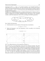
4. Conventional Controller Design
A single-loop unity-feedback control system shown in Figure 3 is considered in the
controller design in this chapter. In this Figure, P(s) is the transfer function of the magnetic
bearing system and C(s) is the transfer function of the controller.
Fig. 3. A single-loop unity-feedback control system
On the basis of the reduced order model described by equation (2), a conventional lead
compensator was designed by using root locus method (Shi & Revell, 2002). Although the
lead compensator has been designed to stabilize the MBC500 magnetic bearing system, its
frequency response has a magnitude which remains large in the high frequency region. This
will affect the stability robustness of the closed-loop system. Thus an additional high
frequency pole at 7000 Hz (or 43982 rad/s) was incorporated to reduce the gain at high
frequency. As a result, the final controller employed in (Shi & Revell, 2002) was a second
order controller (lead with low pass filter with cut off frequency of 7000 Hz) and the transfer
function of the controller is as follows:
Figure 4 illustrates the root locus of the magnetic bearing system represented by the reduced
order model shown in equation (2) with the designed lead compensator shown in equation
(3). The closed-loop poles are at -4.43×10
4
, -2.73×10
3
, and -167±392j respectively. Figure 5
shows the Bode plot of the closed-loop system with and without the added low pass filter. It
can be seen from the Bode plot that the added low pass filter improves the system
robustness by reducing system sensitivity to uncertain high frequency dynamics.
Fig. 4. Root locus of the magnetic bearing system (a reduced 2
nd
-order model is used here)
with the designed lead compensator
Design and implementation of conventional
and advanced controllers for magnetic bearing system stabilization 5
3. System Identification
3.1 System Identification and reduced order model
Since the magnetic bearing system is open-loop unstable, a closed-loop system identification
procedure was required to identify its model. For this purpose, we adopted a two-step
closed-loop system identification procedure (Morse 1996), (Van den Hof & Schrama 1993).
The procedure employs frequency response data. The details of the frequency response
experiment and the system identification procedure were described in (Shi & Revell, 2002).
Various model structures were attempted before an 8
th
-order final model was found. The
transfer function of the 8
th
-order model is shown as follows:
Note that the pole at s=292.7 of the above transfer function indicates the instability of the
open-loop MBC500 magnetic bearing system. Furthermore, it should be noted that when the
model is employed for model-based controller design, closed-loop performance limitations
will also be imposed by the right-half plane zero at s=2854 (Freudenberg & Looze, 1985).
It can be seen from equation (1) that the MBC500 magnetic bearing model includes two
resonant modes. They are located at approximately 780 Hz and 2055 Hz. Each of these two
modes causes an increase in magnitude and a large change in phase in the frequency
response. These characteristics of the resonant modes can threaten the stability of the closed-
loop system. Consequently, two notch filters are designed to eliminate these unwanted
resonances. Since the notch filters must cancel out the resonant modes, the resonant
frequencies of the experimental model must be obtained accurately. Two elliptic notch filters
have been designed to notch out the resonant modes. As a result, controllers can be
designed on the basis of a reduced order unstable system model where the resonant modes
are absent. This reduced order model of the plant can be obtained by eliminating the
resonant modes and preserving the DC gain of the 8
th
-order magnetic bearing system
model. The resulting reduced order model has a transfer function of
4. Conventional Controller Design
A single-loop unity-feedback control system shown in Figure 3 is considered in the
controller design in this chapter. In this Figure, P(s) is the transfer function of the magnetic
bearing system and C(s) is the transfer function of the controller.
Fig. 3. A single-loop unity-feedback control system
On the basis of the reduced order model described by equation (2), a conventional lead
compensator was designed by using root locus method (Shi & Revell, 2002). Although the
lead compensator has been designed to stabilize the MBC500 magnetic bearing system, its
frequency response has a magnitude which remains large in the high frequency region. This
will affect the stability robustness of the closed-loop system. Thus an additional high
frequency pole at 7000 Hz (or 43982 rad/s) was incorporated to reduce the gain at high
frequency. As a result, the final controller employed in (Shi & Revell, 2002) was a second
order controller (lead with low pass filter with cut off frequency of 7000 Hz) and the transfer
function of the controller is as follows:
Figure 4 illustrates the root locus of the magnetic bearing system represented by the reduced
order model shown in equation (2) with the designed lead compensator shown in equation
(3). The closed-loop poles are at -4.43×10
4
, -2.73×10
3
, and -167±392j respectively. Figure 5
shows the Bode plot of the closed-loop system with and without the added low pass filter. It
can be seen from the Bode plot that the added low pass filter improves the system
robustness by reducing system sensitivity to uncertain high frequency dynamics.
Fig. 4. Root locus of the magnetic bearing system (a reduced 2
nd
-order model is used here)
with the designed lead compensator
Magnetic Bearings, Theory and Applications6
Fig. 5. Bode plot of the magnetic bearing system (a reduced 2
nd
-order model is used here)
with the designed lead compensator
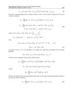
5. Controller Design via Interpolation Approach
5.1 Controller Design via Interpolation Approach
A single-loop unity-feedback control system shown in Figure 3 is considered in the
controller design via the interpolation approach described in (Dorato, 1999). It was shown in
(Dorato, 1999) that any rational transfer function,
where n
p
(s) and d
p
(s) are arbitrary polynomials, can always be written as a ratio of two
coprime stable proper transfer functions,
where
and
with h(s) a Hurwitz polynomial of appropriate degree. Let U(s) be a unit in the algebra of
BIBO stable proper transfer functions, then following (Dorato, 1999) a stable stabilizing
controller can be calculated as:
when P(s) satisfies the parity-interlacing property (p.i.p.) condition (Youla, 1974) and U(s)
satisfies certain interpolation conditions. Specifically, let b
i
denotes the zeros of the plant in
the RHP, the closed-loop system will be internally stable, and the controller will be stable, if
and only if U(s) interpolates to U(b
i
) = D
p
(b
i
) (Dorato, 1999).
5.2 Controller Design for the Magnetic Bearing System
Firstly we note that the reduced order model of the plant described by equation (2) has a
zero at s =2854 and a zero at s =∞. Since the pole at s = 292.7 is not between these two zeros,
the parity-interlacing property (p.i.p.) condition (Youla, 1974) is satisfied and a stable
stabilizing controller is known to exist.
In the following, we assume that the design must satisfy the following specifications:
The sensitivity function is to have all its poles at s =-511,
A steady-state error magnitude (subjected to a unit step input) of e
ss
= 0.1.
Since the closed-loop transfer functions are:
By choosing h(s) = (s + 511)
2
, the requirement of the closed-loop poles specification will be
satisfied. As a result,
and