Mass Transfer in Multiphase Systems and its Applications Part 1 pot
Bạn đang xem bản rút gọn của tài liệu. Xem và tải ngay bản đầy đủ của tài liệu tại đây (1.18 MB, 40 trang )
MASS TRANSFER IN
MULTIPHASE SYSTEMS
AND ITS APPLICATIONS
Edited by Mohamed El-Amin
Mass Transfer in Multiphase Systems and its Applications
Edited by Mohamed El-Amin
Published by InTech
Janeza Trdine 9, 51000 Rijeka, Croatia
Copyright © 2011 InTech
All chapters are Open Access articles distributed under the Creative Commons
Non Commercial Share Alike Attribution 3.0 license, which permits to copy,
distribute, transmit, and adapt the work in any medium, so long as the original
work is properly cited. After this work has been published by InTech, authors
have the right to republish it, in whole or part, in any publication of which they
are the author, and to make other personal use of the work. Any republication,
referencing or personal use of the work must explicitly identify the original source.
Statements and opinions expressed in the chapters are these of the individual contributors
and not necessarily those of the editors or publisher. No responsibility is accepted
for the accuracy of information contained in the published articles. The publisher
assumes no responsibility for any damage or injury to persons or property arising out
of the use of any materials, instructions, methods or ideas contained in the book.
Publishing Process Manager Iva Lipovic
Technical Editor Teodora Smiljanic
Cover Designer Martina Sirotic
Image Copyright timy, 2010. Used under license from Shutterstock.com
First published February, 2011
Printed in India
A free online edition of this book is available at www.intechopen.com
Additional hard copies can be obtained from
Mass Transfer in Multiphase Systems and its Applications, Edited by Mohamed El-Amin
p. cm.
ISBN 978-953-307-215-9
free online editions of InTech
Books and Journals can be found at
www.intechopen.com
Chapter 1
Chapter 2
Chapter 3
Chapter 4
Chapter 5
Chapter 6
Chapter 7
Chapter 8
Preface IX
Mass and Heat Transfer During Two-Phase Flow
in Porous Media - Theory and Modeling 1
Jennifer Niessner and S. Majid Hassanizadeh
Solute Transport With Chemical Reaction
in Singleand Multi-Phase Flow in Porous Media 23
M.F. El-Amin, Amgad Salama and Shuyu Sun
Multiphase Modelling of Thermomechanical
Behaviour of Early-Age Silicate Composites 49
Jiří Vala
Surfactant Transfer in Multiphase Liquid Systems
under Conditions of Weak Gravitational Convection 67
Konstantin Kostarev, Andrew Shmyrov,
Andrew Zuev and Antonio Viviani
Mass Transfer in Multiphase
Mechanically Agitated Systems 93
Anna Kiełbus-Rąpała and Joanna Karcz
Gas-Liquid Mass Transfer in an Unbaffled
Vessel Agitated by Unsteadily Forward-Reverse
Rotating Multiple Impellers 117
Masanori Yoshida, Kazuaki Yamagiwa,
Akira Ohkawa and Shuichi Tezura
Toward a Multiphase Local Approach in the
Modeling of Flotation and Mass Transfer
in Gas-Liquid Contacting Systems 137
Jamel Chahed and Kamel M’Rabet
Mass Transfer in Two-Phase Gas-Liquid Flow
in a Tube and in Channels of Complex Configuration 155
Nikolay Pecherkin and Vladimir Chekhovich
Contents
Contents
VI
Laminar Mixed Convection Heat and Mass Transfer
with Phase Change and Flow Reversal in Channels 179
Brahim Benhamou, Othmane Oulaid,
Mohamed Aboudou Kassim and Nicolas Galanis
Liquid-Liquid Extraction
With and Without a Chemical Reaction 207
Claudia Irina Koncsag and Alina Barbulescu
Modeling Enhanced Diffusion Mass
Transfer in Metals during Mechanical Alloying 233
Boris B. Khina and Grigoriy F. Lovshenko
Mass Transfer in Steelmaking Operations 255
Roberto Parreiras Tavares
Effects of Surface Tension on Mass Transfer Devices 273
Honda (Hung-Ta) Wu and Tsair-Wang Chung
Overall Mass-Transfer Coefficient
for Wood Drying Curves Predictions 301
Rubén A. Ananias, Laurent Chrusciel,
André Zoulalian, Carlos Salinas-Lira and Eric Mougel
Transport Phenomena in Paper
and Wood-based Panels Production 313
Helena Aguilar Ribeiro, Luisa Carvalho,
Jorge Martins and Carlos Costa
Control of Polymorphism and Mass-transfer
in Al
2
O
3
Scale Formed by Oxidation
of Alumina-Forming Alloys 343
Satoshi Kitaoka, Tsuneaki Matsudaira and Masashi Wada
Mass Transfer Investigation
of Organic Acid Extraction with Trioctylamine
and Aliquat 336 Dissolved in Various Solvents 367
Monwar Hossain
New Approaches for Theoretical Estimation
of Mass Transfer Parameters
in Both Gas-Liquid and Slurry Bubble Columns 389
Stoyan Nedeltchev and Adrian Schumpe
Influence of Mass Transfer and Kinetics
on Biodiesel Production Process 433
Ida Poljanšek and Blaž Likozar
Chapter 9
Chapter 10
Chapter 11
Chapter 12
Chapter 13
Chapter 14
Chapter 15
Chapter 16
Chapter 17
Chapter 18
Chapter 19
Contents
VII
Condensation Capture of Fine Dust in Jet Scrubbers 459
M.I. Shilyaev and E.M. Khromova
Mass Transfer in Filtration Combustion Processes 483
David Lempert, Sergei Glazov and Georgy Manelis
Mass Transfer in Hollow Fiber Supported Liquid Membrane
for As and Hg Removal from Produced Water in Upstream
Petroleum Operation in the Gulf of Thailand 499
U. Pancharoen, A.W. Lothongkum and S. Chaturabul
Mass Transfer in Fluidized
Bed Drying of Moist Particulate 525
Yassir T. Makkawi and Raffaella Ocone
Simulation Studies on the Coupling Process
of Heat/Mass Transfer in a Metal Hydride Reactor 549
Fusheng Yang and Zaoxiao Zhang
Mass Transfer around Active Particles in Fluidized Beds 571
Fabrizio Scala
Mass Transfer Phenomena and Biological Membranes 593
Parvin Zakeri-Milani and Hadi Valizadeh
Heat and Mass Transfer
in Packed Bed Drying of Shrinking Particles 621
Manoel Marcelo do Prado and Dermeval José Mazzini Sartori
Impact of Mass Transfer on Modelling
and Simulation of Reactive Distillation Columns 649
Zuzana Švandová, Jozef Markoš and Ľudovít Jelemenský
Mass Transfer through Catalytic Membrane Layer 677
Nagy Endre
Mass Transfer in Bioreactors 717
Ma. del Carmen Chávez, Linda V. González,
Mayra Ruiz, Ma. de la Luz X. Negrete,
Oscar Martín Hernández and Eleazar M. Escamilla
Analytical Solutions of Mass Transfer around a Prolate
or an Oblate Spheroid Immersed in a Packed Bed 765
J.M.P.Q. Delgado and M. Vázquez da Silva
Chapter 20
Chapter 21
Chapter 22
Chapter 23
Chapter 24
Chapter 25
Chapter 26
Chapter 27
Chapter 28
Chapter 29
Chapter 30
Chapter 31
Pref ac e
This book covers a number of developing topics in mass transfer processes in multi-
phase systems for a variety of applications. The book eff ectively blends theoretical,
numerical, modeling, and experimental aspects of mass transfer in multiphase sys-
tems that are usually encountered in many research areas such as chemical, reactor,
environmental and petroleum engineering. From biological and chemical reactors to
paper and wood industry and all the way to thin fi lm, the 31 chapters of this book
serve as an important reference for any researcher or engineer working in the fi eld of
mass transfer and related topics.
The fi rst chapter focuses on the description and modeling of mass transfer processes
occurring between two fl uid phases in a porous medium, while the second chapter is
concerned with the basic principles underlying transport phenomena and chemical
reaction in single- and multi-phase systems in porous media. Chapter 3 introduces the
multiphase modeling of thermomechanical behavior of early-age silicate composites.
The surfactant transfer in multiphase liquid systems under conditions of weak gravita-
tional convection is presented in Chapter 4.
In the fi h chapter the volumetric mass transfer coeffi cient for multiphase mechani-
cally agitated gas–liquid and gas–solid–liquid systems is obtained experimentally.
Further, gas-liquid mass transfer analysis in an unbaffl ed vessel agitated by unsteadily
forward-reverse rotating multiple impellers is provided in Chapter 6. Chapter 7 dis-
cuses the kinetic model of fl otation based on the theory of mass transfer in gas-liquid
bubbly fl ows. The eighth chapter deals with experimental investigation of mass trans-
fer and wall shear stress, and their interaction at the concurrent gas-liquid fl ow in a
vertical tube, in a channel with fl ow turn, and in a channel with abrupt expansion. The
laminar mixed convection with mass transfer and phase change of fl ow reversal in
channels is studied in the ninth chapter, and the tenth chapter exemplifi es the theoreti-
cal aspects of the liquid-liquid extraction with and without a chemical reaction and the
dimensioning of the extractors with original experimental work and interpretations.
The eleventh chapter introduces analysis of the existing theories and concepts of solid-
state diff usion mass transfer in metals during mechanical alloying. In Chapter 12 the
mass transfer coeffi cient is given for diff erent situations (liquid-liquid, liquid-gas and
liquid-solid) of two-phase mass transfer of steelmaking processes. Chapter 13 discuss-
es the eff ect of Marangoni Instability on thin liquid fi lm, thinker liquid layer and mass
transfer devices.
X
Preface
Chapter 14 provides a review of model permi ing the determination of wood drying
rate represented by an overall mass transfer coeffi cient and a driving force. Moreoever,
transport phenomena in paper and wood-based panels’ production are discussed in
Chapter 15.
In the sixteenth chapter the eff ect of lutetium doping on oxygen permeability in poly-
crystalline alumina wafers exposed to steep oxygen potential gradients was evaluated
at high temperatures to investigate the mass-transfer phenomena. Mass transfer in-
vestigation of organic acid extraction with trioctylamine and aliquat336 dissolved in
various solvents is introduced in Chapter 17.
Chapter 18 is focused on the development of semi-theoretical methods for calculation
of gas holdup, interfacial area and liquid-phase mass transfer coeffi cients in gas-liquid
and slurry bubble column reactors. Chapter 19 investigates the infl uence of mass trans-
fer and kinetics on biodiesel (fa y acid alkyl) production process.
The physical-mathematical model of heat and mass transfer and condensation capture
of fi ne dust on fl uid droplets dispersed in jet scrubbers is suggested and analyzed in
Chapter 20, while Chapter 21 is devoted to investigate mass transfer in fi ltration com-
bustion processes.
The twenty-second chapter describes the merits of using hollow fi ber supported liquid
membranes (HFSLM), one of liquid membranes in supported (not clear) structures, and
how mass transfer involves step-by-step in removing arsenic (As) and mercury (Hg).
The twenty-third chapter presents an overview of the various mechanisms contribut-
ing to particulate drying in a bubbling fl uidized bed and the mass transfer coeffi cient
corresponding to each mechanism. A mathematical model and numerical simulation
for hydriding/dehydriding process in a tubular type MH reactor packed with LaNi5
were provided in the twenty-fourth chapter. Chapter 25 is dedicated to the mass trans-
fer coeffi cient around freely moving active particles in the dense phase of a fl uidized
bed. Chapter 26 is aimed at reviewing transport across biological membranes, with
an emphasis on intestinal absorption, its model analysis and permeability prediction.
The objective of the twenty-seventh chapter is to provide comprehensive information
on theoretical-experimental analysis of coupled heat and mass transfer in packed bed
drying of shrinking particles. The twenty-eighth chapter focuses on vapour-liquid
mass transfer infl uence on the prediction of RD column behaviour neglecting the liq-
uid-solid and intraparticle mass transfer. Mass transfer through catalytic membrane
layer is studied in Chapter 29. In chapter 30 three types of bioreactors and stirred tank
applied to biological systems are introduced and a mathematical model is developed.
Finally in Chapter 31 analytical solutions of mass transfer around a prolate or an oblate
spheroid immersed in a packed bed are obtained.
Mohamed Fathy El-Amin
Physical Sciences and Engineering Division
King Abdullah University of Science and Technology (KAUST)
0
Mass and Heat Transfer During Two-Phase Flow in
Porous Media - Theory and Modeling
Jennifer Niessner
1
and S. Majid Hassanizadeh
2
1
Institute of Hydraulic Engineering, University of Stuttgart, Stuttgart
2
Department of Earth Sciences, Faculty of Geosciences, Utrecht University, Utrecht
1
Germany
2
The Netherlands
1. Introduction
1.1 Motivation
This chapter focusses on the description and modeling of mass transfer processes occurring
between two fluid phases in a porous medium. The principle underlying physical process
comprises a transport of particles from one phase to the other phase. This process takes
place across fluid–fluid interfaces (see Fig. 1) and may constitute evaporation, dissolution,
or condensation, for example.
Such mass transfer processes are crucial in many applications involving flow and transport in
porous media. Major examples are found in soil science (where the evaporation from soils is
of interest), soil and groundwater remediation (like thermally-enhanced soil vapor extraction
where dissolution, evaporation, and condensation play a role), storage of carbon dioxide in
the subsurface (where the dissolution of carbon dioxide in the surrounding groundwater is a
crucial storage mechanism), CO
2
-enhanced oil recovery (where after primary and secondary
recovery, carbon dioxide is injected into the reservoir in order to mobilize an additional 8-20
per cent of oil), and various industrial porous systems (such as certain types of fuel cells).
Let us have a closer look at a few of these applications and identify where interphase mass
transfer is relevant. Four specific examples are shown in Fig. 2 and briefly described.
solid phase
fluid
phase 1
fluid phase 2
Fig. 1. Mass transfer processes (evaporation, dissolution, condensation) imply a transfer of
particles across fluid–fluid interfaces.
1
2 Mass Transfer
(a) Carbon dioxide storage in the subsurface
(figure from IPCC (2005))
(b) Soil contamination and remediation
(c) Enhanced oil recovery (figure from
www.oxy.com)
groundwater
precipitation
radiation
evaporation
infiltration
(d) Evaporation from soil
Fig. 2. Four applications of flow and transport in porous media where interphase mass
transfer is important
2
Mass Transfer in Multiphase Systems and its Applications
Mass and Heat Transfer During Two-Phase Flow in Porous Media - Theor y and Modeling 3
(a) Carbon capture and storage (Fig. 2 (a)) is a recent strategy to mitigate the greenhouse
effect by capturing the greenhouse gas carbon dioxide that is emitted e.g. by coal power
plants and inject it directly into the subsurface below an impermeable caprock. Here, three
different storage mechanisms are relevant on different time scales: 1) The capillary barrier
mechanism of the caprock. This geologic layer is meant to keep the carbon dioxide in the
storage reservoir as a separate phase. 2) Dissolution of the carbon dioxide in the surrounding
brine (salty groundwater). This is a longterm storage mechanism and involves a mass
transfer process as carbon dioxide molecules are “transferred” from the gaseous phase to
the brine phase. 3) Geochemical reactions which immobilize the carbon dioxide through
incorporation into the rock matrix.
(b) Shown in Fig. 2 (b) is a cartoon of a light non-aqueous phase liquid (LNAPL)
soil contamination and its clean up by injection of steam at wells located around the
contaminated soil. The idea behind this strategy is to mobilize the initially immobile
(residual) LNAPL by evaporation of LNAPL component at large rates into the gaseous
phase. The soil gas is then extracted by a centrally located extraction well. It means that the
remediation mechanism relies on the evaporation of LNAPL component which represents a
mass transfer from the liquid LNAPL phase into the gaseous phase.
(c) In order to produce an additional 8-20% of oil after primary and secondary recovery,
carbon dioxide may be injected into an oil reservoir, e.g. alternatingly with water, see
Fig. 2 (c). This is called enhanced oil recovery. The advantage of injecting carbon dioxide lies
in the fact that it dissolves in the oil which in turn reduces the oil viscosity, and thus, increases
its mobility. The improved mobility of the oil allows for an extraction of the otherwise
trapped oil. Here, an interphase mass transfer process (dissolution) is responsible for an
improved recovery.
(d) The last example (Fig. 2 (d)) shows the upper part of the soil. The water balance of this part
of the subsurface is extremely important for agriculture or plant growth in general. Plants
do not grow well under too wet or too dry conditions. One of the very important factors
influencing this water balance (besides surface runoff and infiltration) is the evaporation of
water from the soil, which is again an interphase mass transfer process.
1.2 Purpose of this work
Mass transfer processes are essential in a large variety of applications—the presented
examples only show a small selection of systems. A common feature of all these applications is
the fact that the relevant processes occur in relatively large domains such that it is not possible
to resolve the pore structure and the fluid distribution in detail (left hand side of Fig. 3).
Instead, a macro-scale approach is needed where properties and processes are averaged over
a so-called representative elementary volume (right hand side of Fig. 3). This means that the
common challenge in all of the above-mentioned applications is how to describe mass transfer
processes on a macro scale. This transition from the pore scale to the macro scale is illustrated
in Fig. 3 where on the left side, the pore-scale situation is shown (which is impossible to be
resolved in detail) while on the right hand side, the macro-scale situation is shown.
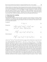
2. Overview of classical mass transfer descriptions
2.1 Pore-scale considerations
In order to better understand the physics of interphase mass transfer, which is essential to
provide a physically-based description of this process, we start our considerations on the pore
3
Mass and Heat Transfer During Two-Phase Flow in Porous Media - Theory and Modeling
4 Mass Transfer
s
solid
phase
w
wetting
fluid phase
n
non−wetting
fluid phase
pore scale
macro scale
Fig. 3. Pore-scale versus macro-scale description of flow and transport in a porous medium.
scale. From there, we try to get a better understanding of the macro-scale physics of mass
transfer, which is our scale of interest.
In Fig. 1 we have seen that interphase mass transfer is inherently a pore-scale process as
it—naturally—takes place across fluid–fluid interfaces. Let us imagine a situation where two
fluid phases, a wetting phase and a non-wetting phase, are brought in contact as shown in
Fig. 4. Commonly, when the two phases are brought in contact (time t
= t
0
), equilibrium is
quickly established directly at the interface. With respect to mass transfer, this means that
the concentration of non-wetting phase particles in the wetting phase at the interface as well
as the concentration of wetting-phase particles in the non-wettting phase at the interface are
both at their equilibrium values, C
2
1,eq
and C
1
2,eq
.Att = t
0
, away from the interface, there
is still no presence of α-phase particles in the β-phase. At a later time t
= t
1
, concentration
profiles develop within the phases. However, within the bulk phases, the concentrations are
still different from the respective equilibrium concentration at the interface. Considering a
still later point of time, t
= t
2
, the equilibrium concentration is finally reached everywhere in
the bulk phases.
These considerations show that mass transfer on the pore scale is inherently a kinetic process
that is very much related to phase-interfaces. But how is this process represented on the macro
scale, i.e. on a volume-averaged scale? This is what we will focus on in the next section.
C
1
2,eq
C
2
1,eq
C
1
2,eq
solid phase
fluid
phase 1
fluid phase 2
C
C
2
1,eq
1
2,eq
C
x
t = t
0
solid phase
fluid
phase 1
fluid phase 2
C
x
t = t
1
solid phase
fluid
phase 1
fluid phase 2
C
x
t = t
2
C
2
1,eq
Fig. 4. Pore-scale picture of interphase mass transfer.
4
Mass Transfer in Multiphase Systems and its Applications
Mass and Heat Transfer During Two-Phase Flow in Porous Media - Theor y and Modeling 5
2.2 Current macro-scale descriptions
In Fig. 3, we illustrated the fact that when going from the pore scale to the macro scale,
information about phase-interfaces is lost. The only information present on the macro scale is
related to volume ratios, such as porosity and fluid saturations. But, as mentioned earlier,
mass transfer is strongly linked to the presence of interfaces and interfacial areas and all
the information about phase-interfaces disappears on the macro scale. This means that the
description of mass transfer on the macro scale is not straight forward. Classical approaches
for describing mass transfer generally rely on one of the following two principles:
1. assumption of local chemical equilibrium within an averaging volume or
2. kinetic description based on a fitted (linear) relationship.
These two classical approaches will be discussed in more detail in the following. An
alternative approach which accounts for the phase-interfacial area will be presented later in
Sec. 3.
2.2.1 Local equilibrium assumption
The assumption of local chemical equilibrium within an averaging volume means that the
equilibrium concentrations are reached instantaneously everywhere within an averaging
volume (in both phases). That means it is assumed that everywhere within the averaging
volume, the situation at t
= t
2
in Fig. 4 is reached from the beginning (t = t
0
). Thus, at each
point in the wetting phase and at each point in the non-wetting phase within the averaging
volume, the equilibrium concentration of the components of the other phase is reached.
This is an assumption which may be good in case of fast mass transfer, but bad in case of
slow mass transfer processes. To be more precise, the assumption that the composition of
a phase is at or close to equilibrium may be good if the characteristic time of mass transfer
is small compared to that of flow. However, if large flow velocities occur as e.g. during air
sparging, the local equilibrium assumption gives completely wrong results, see Falta (2000;
2003) and van Antwerp et al. (2008). We will investigate and quantify this issue later in Sec. 3.3
.
Local equilibrium models for multi-phase systems have been introduced and developed
e.g. by Miller et al. (1990); Powers et al. (1992; 1994); Imhoff et al. (1994); Zhang & Schwartz
(2000) and have been used and advanced ever since. Let us consider a system with a liquid
phase (denoted by subscript l) and a gaseous phase (denoted by subscript g) composed of
air and water components. Then, Henry’s Law is employed to determine the mole fraction
of air in the liquid phase, while the mole fraction of water in the gas phase is determined by
assuming that the vapor pressure in the gas phase is equal to the saturation vapor pressure.
Denoting the water component by superscript w and the air component by superscript a, this
yields
x
a
l
= p
a
g
· H
a
l
−g
(1)
x
w
g
=
p
w
sat
p
g
, (2)
where x
a
l
[−] is the mole fraction of air in the liquid phase, x
w
g
[−] is the mole fraction of water
in the gaseous phase, H
a
l
−g
1
Pa
is the Henry constant for the dissolution of air in the liquid
phase, p
w
sat
[Pa] is the saturation vapor pressure of water, p
a
g
[Pa] is the partial pressure of air
5
Mass and Heat Transfer During Two-Phase Flow in Porous Media - Theory and Modeling
6 Mass Transfer
in the gas phase while p
g
[Pa] is the gas pressure. The remaining mole fractions result simply
from the condition that mole fractions in each phase have to sum up to one,
x
w
l
= 1 − x
a
l
(3)
x
a
g
= 1 − x
w
g
. (4)
Note that while for a number of applications the equilibrium mole fractions are constants or
merely a function of temperature, in our case, they will be functions of space and time as
pressure and the composition of the phases changes.
2.2.2 Classical kinetic approach
Kinetic mass transfer approaches are traditionally applied to the dissolution of contaminants
in the subsurface which form a separate phase from water, the so-called non-aqueous phase
liquids (NAPLs). If such a non-aqueous phase liquid is heavier than water, it is called
“dense non-aqueous phase liquid” or DNAPL. When an immobile lense of DNAPL is present
at residual saturation (i.e. at a saturation which is so low that the phase is immobile) and
dissolves into the surrounding groundwater, the kinetics of this mass transfer process usually
plays an important role: the dissolution of DNAPL is a rate-limited process. This is also
the case when a pool of DNAPL is formed on an impermeable layer. In these relatively
simple cases, only the mass transfer of a DNAPL component from the DNAPL phase into
the water phase has to be considered. For these cases, classical models acknowledge the
fact that the rate of mass transfer is highly dependent (proportional to) interfacial area and
assume a first-order rate of kinetic mass transfer between fluid phases in a porous medium
on a macroscopic (i.e. volume-averaged) scale which can be expressed as (see e.g. Mayer &
Hassanizadeh (2005)):
Q
κ
α
→β
= k
κ
α
→β
a
αβ
(C
κ
β,s
−C
κ
β
), (5)
where Q
κ
α
→β
kg
m
3
s
is the interphase mass transfer rate of component κ from phase α to
phase β, k
κ
α
→β
m
s
is the mass transfer rate coefficient, a
αβ
1
m
is the specific interfacial
area separating phases α and β, C
κ
β,s
kg
m
3
is the solubility limit of component κ in phase
β, and finally, C
κ
β
kg
m
3
is the actual concentration of component κ in phase β. The actual
concentration is not larger than the solubility limit, C
κ
β
≤ C
κ
β,s
. The case C
κ
β
= C
κ
β,s
corresponds
to the local equilibrium case.
In the absence of a physically-based estimate of interfacial area in classical kinetic models, the
mass transfer coefficient k
κ
α
→β
and the specific interfacial area a
αβ
are often lumped into one
single parameter (Miller et al. (1990); Powers et al. (1992; 1994); Imhoff et al. (1994); Zhang &
Schwartz (2000)). This yields, in a simplified notation,
Q
= k(C
s
−C). (6)
Here, C
s
is the solubility limit of the DNAPL component in water and C is its actual
concentration. The lumped mass transfer coefficient k
1
s
is commonly related to a modified
Sherwood number Sh by
k
= Sh
D
m
d
2
50
, (7)
6
Mass Transfer in Multiphase Systems and its Applications
Mass and Heat Transfer During Two-Phase Flow in Porous Media - Theor y and Modeling 7
where D
m
m
2
s
is the aqueous phase molecular diffusion coefficient, and d
50
[m] is the mean
size of the grains. The Sherwood number is then related to Reynold’s number Re and DNAPL
saturation S
n
[−] by
Sh
= pRe
q
S
r
n
, (8)
where p, q, and r are dimensionless fitting parameters. This is a purely empirical relationship.
Although interphase mass transfer is proportional to specific interfacial area in the original
Eq. (5), this dependence cannot explicitly be accounted for as the magnitude of specific
interfacial area is not known.
An alternative classical approach for DNAPL pool dissolution has been proposed by Falta
(2003) who modeled the dissolution of DNAPL component by a dual domain approach
for a case with simple geometry. For this purpose, they divided the contaminated porous
medium into two parts: one that contains DNAPL pools and one without DNAPL. For
their simple case, the dual domain approach combined with an analytical solution for
steady-state advection and dispersion provided a means for modeling rate-limited interphase
mass transfer. While this approach provided good results for the case of simplified geometry,
it might be oversimplified for the modeling of realistic situations.
3. Interfacial-area-based approach for mass transfer description
3.1 Theoretical background
Due to a number of deficiencies of the classical model for two-phase flow in porous media
(one of which is the problem in describing kinetic interphase mass transfer on the macro
scale), several approaches have been developed to describe two-phase flow in an alternative
and thermodynamically-based way. Among these are a rational thermodynamics approach
by Hassanizadeh & Gray (1980; 1990; 1993b;a), a thermodynamically constrained averaging
theory approach by Gray and Miller (e.g. Gray & Miller (2005); Jackson et al. (2009)),
mixture theory (Bowen (1982)) and an approach based on averaging and non-equilibrium
thermodynamics by Marle (1981) and Kalaydjian (1987). While Marle (1981) and Kalaydjian
(1987) developed their set of constitutive relationships phenomenologically, Hassanizadeh &
Gray (1990; 1993b); Jackson et al. (2009), and Bowen (1982) exploited the entropy inequality
to obtain constitutive relationships. To the best of our knowledge, the two-phase flow models
of Marle (1981); Kalaydjian (1987); Hassanizadeh & Gray (1990; 1993b); Jackson et al. (2009)
are the only ones to include interfaces explicitly in their formulation allowing to describe
hysteresis as well as kinetic interphase mass and energy transfer in a physically-based way. In
the following, we follow the approach of Hassanizadeh & Gray (1990; 1993b) as it includes
the spatial and temporal evolution of phase-interfacial areas as parameters which allows
us to model kinetic interphase mass transfer in a much more physically-based way than is
classically done.
It has been conjectured by Hassanizadeh & Gray (1990; 1993b) that problems of the classical
two-phase flow model, like the hysteretic behavior of the constitutive relationship between
capillary pressure and saturation, are due to the absence of interfacial areas in the theory.
Hassanizadeh and Gray showed (Hassanizadeh & Gray (1990; 1993b)) that by formulating
the conservation equations not only for the bulk phases, but additionally for interfaces,
and by exploiting the residual entropy inequality, a relationship between capillary pressure,
saturation, and specific interfacial areas (interfacial area per volume of REV) can be derived.
This relationship has been determined in various experimental works (Brusseau et al. (1997);
Chen & Kibbey (2006); Culligan et al. (2004); Schaefer et al. (2000); Wildenschild et al. (2002);
7
Mass and Heat Transfer During Two-Phase Flow in Porous Media - Theory and Modeling
8 Mass Transfer
Chen et al. (2007)) and computational studies (pore-network models and CFD simulations
on the pore scale, see Reeves & Celia (1996); Held & Celia (2001); Joekar-Niasar et al. (2008;
2009); Porter et al. (2009)). The numerical work of Porter et al. (2009) using Lattice Boltzman
simulations in a glass bead porous medium and experiments of Chen et al. (2007) show
that the relationship between capillary pressure, the specific fluid-fluid interfacial area, and
saturation is the same for drainage and imbibition to within the measurement error. This
allows for the conclusion that the inclusion of fluid–fluid interfacial area into the capillary
pressure–saturation relationship makes hysteresis disappear or, at least, reduces it down
to a very small value. Niessner & Hassanizadeh (2008; 2009a;b) have modeled two-phase
flow—using the thermodynamically-based set of equations developed by Hassanizadeh &
Gray (1990)—and showed that this interfacial-area-based model is indeed able to model
hysteresis as well as kinetic interphase mass and also energy transfer in a physically-based
way.
3.2 Simplified model
After having presented the general background of our interfacial-area-based model, we will
now proceed by discussing the mathematical model. The complete set of balance equations
based on the approach of Hassanizadeh & Gray (1990) is too large to be handled numerically.
In order to do numerical modeling, simplifying assumptions need to be made. In the
following, we present such a simplified equation system as was derived in Niessner &
Hassanizadeh (2009a).
This set of balance equations can be described by six mass and three momentum balance
equations. These numbers result from the fact that mass balances for each component of each
phase and the fluid–fluid interface (that is 2
×3) while momentum balances are given for the
bulk phases and the interface. Governing equations were derived by Hassanizadeh & Gray
(1979) and Gray & Hassanizadeh (1989; 1998) for the case of flow of two pure fluid phases
with no mass transfer. Extending these equations to the case of two fluid phases, each made
of two components, we obtain the following equations.
mass balance for phase components (κ
= w, a):
∂
φS
l
¯
ρ
l
¯
X
κ
l
∂t
+ ∇·
(
φS
l
¯
ρ
l
¯
X
κ
l
¯
v
l
)
−∇·
φS
l
¯
j
κ
l
=
¯
ρ
l
Q
κ
l
+
1
V
A
lg
ρ
l
X
κ
l
v
lg
−v
l
+ j
κ
l
·n
lg
dA (9)
∂
φS
g
¯
ρ
g
¯
X
κ
g
∂t
+ ∇·
φS
g
¯
ρ
g
¯
X
κ
g
¯
v
g
−∇·
φS
g
¯
j
κ
g
=
¯
ρ
g
Q
κ
g
+
1
V
A
lg
ρ
g
X
κ
g
v
g
−v
lg
− j
κ
g
·n
lg
dA (10)
mass balance for lg-interface components (κ
= w, a):
∂
¯
Γ
lg
¯
X
κ
lg
a
lg
∂t
+ ∇·
¯
Γ
lg
¯
X
κ
lg
a
lg
¯
v
lg
−∇·
¯
j
κ
lg
a
lg
−
=
1
V
A
lg
ρ
l
X
κ
l
v
l
−v
lg
− j
κ
l
−ρ
g
X
κ
g
v
g
−v
lg
+ j
κ
g
·n
lg
dA (11)
8
Mass Transfer in Multiphase Systems and its Applications
Mass and Heat Transfer During Two-Phase Flow in Porous Media - Theor y and Modeling 9
momentum balance for phases:
∂
(
φS
l
¯
ρ
l
¯
v
l
)
∂t
+ ∇·
(
φS
l
¯
ρ
l
¯
v
l
¯
v
l
)
−∇·
(
φS
l
T
l
)
=
1
V
A
lg
ρ
l
v
l
v
lg
−v
l
+ t
l
·n
lg
dA (12)
∂
φS
g
¯
ρ
g
¯
v
g
∂t
+ ∇·
φS
g
¯
ρ
g
¯
v
g
¯
v
g
−∇·
φS
g
T
g
=
1
V
A
lg
ρ
g
v
g
v
g
−v
lg
−t
g
·n
lg
dA (13)
momentum balance for lg-interface:
∂
¯
Γ
lg
¯
v
lg
a
lg
∂t
+ ∇·
¯
Γ
lg
¯
v
lg
a
lg
¯
v
lg
−∇·
T
lg
a
lg
=
1
V
A
lg
ρ
l
v
l
v
l
−v
lg
−t
l
−ρ
g
v
g
v
g
−v
lg
+ t
g
·n
lg
dA, (14)
where the overbars denote volume-averaged (macro-scale) quantities. Here, X
κ
α
[−] is the
mass fraction of component κ in phase α, t is time, Q
κ
α
m
3
s
is an external source of component
κ in phase α, j
κ
α
kg·m
4
s
is the diffusive flux of component κ in phase α, V is the magnitude of
the averaging volume, A
lg
denotes the interfaces separating the l-phase and the g-phase in an
averaging volume, v
lg
m
s
is the velocity of the lg-interface, and n
lg
is the unit vector normal
to A
lg
and pointing into the g-phase. Furthermore, X
κ
lg
[−] is the mass fraction of component κ
in the lg-interface, j
κ
lg
kg·m
4
s
is the diffusive flux of component κ in the lg-interface, t
α
kg
m·s
2
is the α-phase micro-scale stress tensor, T
α
kg
s
2
is the α-phase macro-scale stress tensor, and
T
lg
kg
s
2
is the macro-scale lg-interfacial stress tensor.
In the following, we provide a simplified version of Eq. (9) through (14). First, we assume
that the composition of the interface does not change. This is a reasonable assumption as long
as no surfactants are involved. This reduces the number of balance equations to eight, as we
can sum up the mass balance equations for interface components. Furthermore, we assume
that momentum balances can be simplified so far that we end up with Darcy-like equations
for both bulk phases and interface. We further proceed by applying Fick’s law to relate the
micro-scale diffusive fluxes j
κ
α
to the local concentration gradient resulting in the following
approximation:
j
κ
α
·n
lg
= ±
ρ
α
D
κ
d
κ
a
lg
X
κ
α,s
− X
κ
α
, (15)
where D
κ
m
2
s
is the micro-scale Fickian diffusion coefficient for component κ, d
κ
[m] is the
diffusion length of component κ, X
κ
α,s
[−] is the solubility limit of component κ in phase α
(i.e. the mass fraction corresponding to local equilibrium), and X
κ
α
[−] is the micro-scale mass
fraction of component κ in phase α at a distance d
κ
away from the interface. Niessner &
9
Mass and Heat Transfer During Two-Phase Flow in Porous Media - Theory and Modeling
10 Mass Transfer
Hassanizadeh (2009a) obtained the following determinate set of macro-scale equations:
∂
φS
l
¯
ρ
l
¯
X
w
l
∂t
+ ∇·
(
¯
ρ
l
¯
X
w
l
¯
v
l
)
−∇·
¯
j
w
l
= ρ
l
Q
w
l
−
D
w
¯
ρ
g
d
w
a
lg
X
w
g,s
− X
w
g
(16)
∂
φS
l
¯
ρ
l
¯
X
a
l
∂t
+ ∇·
(
¯
ρ
l
¯
X
a
l
¯
v
l
)
−∇·
¯
j
a
l
= ρ
l
Q
a
l
+
D
a
¯
ρ
l
d
a
a
lg
X
a
l,s
− X
a
l
(17)
∂
φS
g
¯
ρ
g
¯
X
w
g
∂t
+ ∇·
¯
ρ
g
¯
X
w
g
¯
v
g
−∇·
¯
j
w
g
= ρ
g
Q
w
g
+
D
w
¯
ρ
g
d
w
a
lg
X
w
g,s
− X
w
g
(18)
∂
φS
g
¯
ρ
g
¯
X
a
g
∂t
+ ∇·
¯
ρ
g
¯
X
a
g
¯
v
g
−∇·
¯
j
a
g
= ρ
g
Q
a
g
−
D
a
¯
ρ
l
d
a
a
lg
X
a
l,s
− X
a
l
(19)
∂a
lg
∂t
+ ∇·
a
lg
v
lg
= E
lg
(20)
¯
v
l
= −K
S
2
l
μ
l
∇p
l
−
¯
ρ
l
g
(21)
¯
v
g
= −K
S
2
g
μ
g
∇p
g
−
¯
ρ
g
g
(22)
¯
v
lg
= −K
lg
∇a
lg
(23)
p
c
= p
g
− p
l
(24)
S
l
+ S
g
= 1 (25)
X
w
l
+ X
a
l
= 1 (26)
X
w
g
+ X
a
g
= 1 (27)
a
lg
= a
lg
(S
l
, p
c
), (28)
The macro-scale mass fluxes
¯
j
κ
α
are given by a Fickian dispersion equation,
¯
j
κ
α
= −ρ
α
¯
D
κ
α
∇
(
¯
X
κ
α
)
, (29)
where
¯
D
κ
α
is the macro-scale dispersion coefficient. Note that in Eq. (16) through (19), we
have acknowledged the fact that an internal source of a component in one of the phases
must correspond to a sink of that component of equal magnitude in the other phase. The
solubility limits X
w
g,s
and X
a
l,s
are obtained from a local equilibrium assumption at the
fluid–fluid interface. If, for example, we consider a two-phase–two-component air–water
system solubility limits with respect to mole fractions are given by Eqs. (1) and (2).
10
Mass Transfer in Multiphase Systems and its Applications
Mass and Heat Transfer During Two-Phase Flow in Porous Media - Theor y and Modeling 11
3.3 Is a kinetic approach necessary?
Depending on the parameters, initial conditions, and boundary conditions of the system,
kinetics might be important for mass transfer. If so, then it may not be sufficient to use a
classical local equilibrium model instead of the more complex interfacial-area-based model.
To allow for a decision, Niessner & Hassanizadeh (2009a) make the system of equations (16)
through (28) dimensionless and study the dependence of kinetics on Damk
¨
ohler number and
Peclet number.
To do so, they define dimensionless variables:
t
∗
=
tv
R
φL
,
∇
∗
= L∇,
¯
v
∗
α
=
¯
v
α
v
R
, Q
κ∗
α
=
Q
κ
α
L
X
κ
α,s
v
R
, (30)
a
∗
lg
=
a
lg
a
R,lg
,
¯
D
κ∗
α
=
¯
D
κ
α
D
R,α
, v
∗
lg
=
φ
v
R
v
lg
, (31)
E
∗
lg
=
a
R,lg
φL
v
R
E
lg
, g
∗
α
=
¯
ρ
α
gL
p
R
, K
∗
lg
=
φK
lg
La
R,lg
v
R
, (32)
p
∗
α
=
p
α
p
R
, p
∗
c
=
p
c
p
R
, ρ
∗
g
=
¯
ρ
g
¯
ρ
l
μ
∗
l
=
μ
l
μ
g
. (33)
Here, ρ
∗
g
is density ratio, μ
∗
l
is viscosity ratio, v
R
is a reference velocity, L is a characteristic
length, a
R,lg
is a reference specific interfacial area, D
R,α
is a reference dispersion coefficient,
and p
R
is a reference pressure. We assume that p
R
and v
R
can be chosen such that
Kp
R
μ
l
v
R
L
= 1.
Also, Peclet number Pe
α
and Damk
¨
ohler number Da
κ
are defined by
Pe
α
=
v
R
L
D
R,α
,Da
κ
=
D
κ
La
R,lg
dv
R
. (34)
These definitions lead to the following dimensionless form of Eq. (16) through (28):
∂
∂t
∗
(
S
l
¯
X
w
l
)
+ ∇
∗
·
(
¯
X
w
l
v
∗
l
)
−∇
∗
·
D
w∗
l
Pe
l
∇
∗
¯
X
w
l
= Q
w∗
l
−Da
w
a
∗
lg
ρ
∗
g
X
w
g,s
−
¯
X
w
g
(35)
∂
∂t
∗
(
S
l
¯
X
a
l
)
+ ∇
∗
·
(
¯
X
a
l
v
∗
l
)
−∇
∗
·
D
a∗
l
Pe
l
∇
∗
¯
X
a
l
= Q
a∗
l
+ Da
a
a
∗
lg
X
a
l,s
−
¯
X
a
l
(36)
∂
∂t
∗
S
g
¯
X
w
g
+ ∇
∗
·
¯
X
w
g
v
∗
g
−∇
∗
·
D
w∗
g
Pe
g
∇
∗
¯
X
w
g
= Q
w∗
g
+ Da
w
a
∗
lg
X
w
g,s
−
¯
X
w
g
(37)
∂
∂t
∗
S
g
¯
X
a
g
+ ∇
∗
·
¯
X
a
g
v
∗
g
−∇
∗
·
D
a∗
g
Pe
g
∇
∗
¯
X
a
g
= Q
a∗
g
−Da
a
a
∗
lg
1
ρ
∗
g
X
a
l,s
−
¯
X
a
l
(38)
∂a
∗
lg
∂t
∗
+ ∇
∗
·
a
∗
lg
v
∗
lg
= E
∗
lg
(39)
v
∗
l
= −S
2
l
∇
∗
p
∗
l
− g
∗
l
(40)
v
∗
g
= −S
2
g
μ
∗
l
∇
∗
p
∗
g
− g
∗
g
(41)
11
Mass and Heat Transfer During Two-Phase Flow in Porous Media - Theory and Modeling
12 Mass Transfer
v
∗
lg
= −K
∗
lg
∇
∗
a
∗
lg
(42)
p
∗
c
= p
∗
g
− p
∗
l
(43)
S
l
+ S
g
= 1 (44)
¯
X
w
l
+
¯
X
a
l
= 1 (45)
¯
X
w
g
+
¯
X
a
g
= 1 (46)
a
∗
lg
= a
∗
lg
(
S
l
, p
∗
c
)
. (47)
In order to investigate the importance of kinetics, we define Pe :
= Pe
l
= Pe
g
and Da := Da
w
=
Da
a
and vary Pe and Da independently over five orders of magnitude. Therefore, we consider
a numerical example where dry air is injected into a horizontal (two-dimensional) porous
medium of size 0.7 m
× 0.5 m that is almost saturated with water (initial and boundary water
saturation of 0.9).
Fig. 5 shows a comparison of actual mass fractions
¯
X
a
l
and
¯
X
w
g
to solubility mass fractions X
a
l,s
and X
w
g,s
for five different Damk
¨
ohler numbers. Therefore, a cut through the domain is shown
and two different time steps are compared.
0.014
0m 0.7m
t = 0.01s
t = 0.0035s
4.0E-5
0m
0.7m
4.0E-5
0m
0.7m
0.014
0m 0.7m
4.0E-5
0m
0.7m
0.014
0m 0.7m
4.0E-5
0m
0.7m
4.0E-5
0m
0.7m
4.0E-5
0m
0.7m
4.0E-5
0m
0.7m
0.014
0m 0.7m
4.0E-5
0m
0.7m
0.014
0m 0.7m
0.014
0m 0.7m
0.014
0m 0.7m
0.014
0m 0.7m
4.0E-5
0m
0.7m
0.014
0m 0.7m
0.014
0m 0.7m
4.0E-5
0m
0.7m
Da=0.1 Da Da=Da Da=10 Da Da=100 Da
solubility limit
actual mass fraction
l
a
000 0 0
Da=0.01 Da
l
a
w
g
w
g
X [−]
xxxx x
x
x
x
xxxx
xxxx
xxxx
0
0.7
0
0
0
0.7
0
0
0.7
0
0
0.7
0.70
0
0.0140.0140.014 0.014 0.014
0
0
0.7
0.70
00
0 0.7
0
0 0.7
0
0 0.7
0
0
0.7
0.014 0.014
0
0
0.7
0.014
0
0
0.7
0.014
0
0
0.7
0.014
0
0
0.7
0
0.7
0
0
0
0.7
0
0
0.7
0
0
0.7
0
0
0.7
4E−5 4E−5 4E−5 4E−5 4E−5
X [−]
4E−5 4E−5 4E−5 4E−5 4E−5
X [−]
X [−]
Fig. 5. Solubility limits X
a
l,s
and X
w
g,s
and actual mass fractions
¯
X
a
l
and
¯
X
w
g
for two different
time steps (0.0035 s and 0.01 s) and 5 different Damk
¨
ohler numbers.
12
Mass Transfer in Multiphase Systems and its Applications
Mass and Heat Transfer During Two-Phase Flow in Porous Media - Theor y and Modeling 13
It can be seen that the system is practically instantaneously in equilibrium with respect to the
mass fraction
¯
X
w
g
(water mass fraction in the gas phase) for the whole range of considered
Damk
¨
ohler numbers (see the second and forth row of graphs). With respect to the mass
fraction
¯
X
a
l
(air mass fraction in the water phase), for low Damk
¨
ohler numbers and early times,
the system is far from equilibrium (see the first and third row of graphs). With increasing
time and with increasing Damk
¨
ohler number, the system approaches equilibrium. As for
high Damk
¨
ohler numbers mass transfer is very fast, an ”overshoot“ occurs and the system
becomes oversaturated before it reaches equilibrium.
One might argue that the considered time steps are extremely small and not relevant for the
time scale relevant for the whole domain. However, what happens at this very early time has
a large influence on the state of the system at all subsequent times.
It turned out that for different Peclet numbers, there is no difference in results. That means
that kinetic interphase mass transfer is independent of Peclet number, at least within the four
orders of magnitude considered here.
4. Extension to heat transfer
The concept of describing mass transfer based on modeling the evolution of interfacial areas
using the thermodynamically-based approach of Hassanizadeh & Gray (1990; 1993b) can
be extended to describing interphase heat transfer as well. The main difference between
interphase mass and heat transfer is that, in addition to fluid–fluid interfaces, heat can also be
transferred across fluid–solid interfaces, see Fig. 6.
Similarly to mass transfer, classical two-phase flow models describe heat transfer on the
macro scale by either assuming local thermal equilibrium within an averaging volume or
by formulating empirical models to describe the transfer rates. The latter is necessary
as classically, both fluid–fluid and fluid–solid interfacial areas are unknown on the macro
scale. And similiarly to mass transfer, we can use the thermodynamically-based approach
of Hassanizadeh & Gray (1990; 1993b) which includes both fluid–fluid and fluid–solid
interfacial areas in order to describe mass transfer in a physically-based way. We can
non−wetting
wetting
(1)
m
ass
t
r
a
n
s
f
e
r
non−wetting
wetting
(2)
h
eat
t
r
a
n
s
f
e
r
Fig. 6. Mass transfer takes place across fluid–fluid interfaces (left hand side) and heat transfer
across fluid–fluid as well as fluid–solid interfaces (right hand side)
13
Mass and Heat Transfer During Two-Phase Flow in Porous Media - Theory and Modeling