Mobile Ad Hoc Networks Applications Part 11 doc
Bạn đang xem bản rút gọn của tài liệu. Xem và tải ngay bản đầy đủ của tài liệu tại đây (568.16 KB, 35 trang )
MANET Mining: Mining Association Rules 19
This swap is equivalent to dropping one of the two similar bit-vectors in the bit-matrix. Since
there is utterly no difference between the s ource and the destination matrices the s ame MFSs
(key) are obtained.
Wormhole attacks do not affect KDTM. Wormhole leaks routed packets at a node to the
outside world. Still the MFSs built from the leaked packets is not the same as that of the e nd
nodes because not all traffic from the source to the d estination pass through the same route.
KDTM is immune to Man-in-Middle (MIM) attack s. In passive MIM attack, the malicious
node just builds and mines its bit-matrix, however, the resultant MFS obtained is different
from that of the end nodes. Still in this situation, the MFS obtained at the end nodes is
not affected because MIM does not alter the bit-vector of both passing data packets and
passing ACK . Two scenarios are observed in active MIM attacks. The first scenario, the
malicious node forges/modifies the bit-vector of the passing data packets. This means the
same alteration is reflected in both the bit-matrices of the end nodes. In the s econd scenario,
the MIM alters the bit-vector of the passing ACK. This means the same c hange is induced in
the source bit-matrix but not in the d estination bit-matrix. T he difference induced between
source and destination bit-matrices is insufficient, because a small number of ACK pass
through the s ame route; and therefore, the same MFS obtained at the end nodes.
Notably, active MIM can be identified through checking of bit-vector by routing nodes before
sending it to the next node; and if any node discover that its bit (or the bits of her neighbors
who have not received the packet) is changed, then this node should send a warning message
to the other nodes in the MANET that there is an active MIM in the network.
Simulation re sults show that KDTM is tolerant, in that adding/deleting bit-vectors randomly
to/from bit matrix up to 30 % does not change the resultant MFS.Furthermore,KDTM
allows concatenating several MFSs or keys in a bid to develop a stronger key.
KDTM may applies Nitin’s watch dog and Pathrater concepts to eliminate malicious
nodes in the transmission range of the end nodes so that the extracted key is not
compromised ( Kyasanur & Vaidya, 2003).
KDTM is a new cross layer key distribution scheme, which extracts MFS from network layer
to be used in other layers, for instance, the application l ayer.
6.3 Key revocation
Key disclosure is very frequent in MANET. T here is no guarantee that the route between the
communicating nodes is free of malicious no des.
In contrast to using static long-term keys, dynamic short-term cryptographic keys can be
used to minimize the availability of ciphertext, encrypted with the same key, and therefore,
making it difficult to compromise the key (Menezes et al., 1996). Accordingly, key renewal is
compulsory to reduce the amount of disclosed packets in case the key is compromised. In the
new method, key renewal, not affected by any other factor and is very simple because the key
is mined as long as there is traffic, may be done at any time.
Key can be changed periodically between the two communicating nodes. The parameters
such as Support σ, Mining Rate Δ and step threshold λ may b e changed to mislead the MIM.
This is somehow similar to frequency hopping in wireless communication used for security
purpose.
The n ext two sections analyze mathematically and experimentally the new framework.
341
MANET Mining: Mining Association Rules
20 Theory and Applications of Ad Hoc Networks
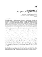
n = 0 C(0,0)
n = 1 C(1,0) C(1,1)
n = 2 C(2,0) C(2, 1) C(2, 2)
n = 3 C(3,0) C(3, 1) C(3, 2) C(3, 2)
n
= nC( n,0) C(n,1) C(n, i − 1) C(n, i)
Fig. 7. Pascal triangle
6.4 Mathematical analysis of the new framework
One of the main features of A priori algorithm is tolerance, i n the sense that arbitrarily adding
some rows (bit-vectors) with random values to the data set (bit-matrix) does not affect the
end result (outcome), and therefore, the same MFS is obtained. Further more, deleting some
rows (bit-vectors) randomly from a data set (bit-matrix), does not change the output of the
algorithm. At the same time, it is very difficult to guess the output of the algorithm without
acquiring the whole bit-matrix.
The algorithm can be applied on three different types of traffic. The first type is the data
traffic. The algorithm extracts the MFSs from the bit-matrix of bit-vectors of data packets.
The second t ype is the acknowledgement traffic and the third type i s a mixture of data and
acknowledgement packets.
Consider a MANET with a set of n nodes. The output of Apriori algorithm is MFSs in an
increasing order and without repetition. The number of ways to form MFS of length i is:
C
(n,i) (1)
i n 100 150 200 250 300 350 400 450 500 550 600
03 2
18
2
20
2
21
2
22
2
23
2
23
2
24
2
24
2
25
2
25
2
25
04 2
23
2
25
2
27
2
28
2
29
2
30
2
31
2
31
2
32
2
32
2
32
05 2
27
2
30
2
32
2
33
2
35
2
36
2
37
2
38
2
38
2
39
2
39
06 2
31
2
35
2
37
2
39
2
40
2
42
2
43
2
44
2
45
2
46
2
46
07 2
35
2
39
2
42
2
44
2
46
2
47
2
49
2
50
2
51
2
52
2
52
08 2
39
2
43
2
47
2
49
2
51
2
53
2
54
2
56
2
57
2
58
2
58
09 2
42
2
47
2
51
2
54
2
56
2
58
2
60
2
61
2
63
2
64
2
64
10 2
46
2
51
2
55
2
59
2
61
2
63
2
65
2
67
2
68
2
70
2
70
11 2
49
2
55
2
60
2
63
2
66
2
68
2
71
2
72
2
74
2
76
2
76
12 2
52
2
59
2
64
2
68
2
71
2
73
2
76
2
78
2
79
2
81
2
82
13 2
55
2
63
2
68
2
72
2
75
2
78
2
81
2
83
2
85
2
87
2
87
14 2
58
2
73
2
72
2
76
2
80
2
83
2
85
2
88
2
90
2
92
2
93
15 2
61
2
76
2
76
2
80
2
84
2
87
2
90
2
93
2
95
2
97
2
98
16
—————————————
Δ
Higher Security
Δ
——————————–
Higher Security
Ta ble 5. A combinatoric relationship (C(n, i)) between n and i,wheren ≡ number of nodes
and i
≡ length of MFS.
342
Mobile Ad-Hoc Networks: Applications
MANET Mining: Mining Association Rules 21
Accordingly, all the possible ways to form an MFS of variable length i is:
C
(n,2)+C(n,3)+ + C(n,i)+ + C(n, n − 1)+C(n, n)
(
where 2 ≤ i ≤ n
)
(2)
Seefigure7,thesumofthenth row of Pascal triangle is given by (Mott et al., 1992):
C
(n,0)+C(n,1)+C(n,2)+ + C(n,i)+ + C(n, n − 1)+C(n, n)= 2
n
(3)
From 2 and 3, the total number of ways is:
C
(n,2)+ + C(n,i)+ + C(n,n − 1)+C(n,n)=2
n
− (n + 1) (4)
If i = 2, then the source and the destination are neighbors, that means no intermediate nodes.
If i
= n then the topology is chained.
Equation 4 assumes that t he MFS may contain any number of nodes not exceeding n. In fact,
this may be correct in one case only, a chain network topology. For example, queue of soldiers
following their commander.
The number of routing nodes related to several factors, namely the routing protocol,
sending/receiving range, and so on.
6.5 Experimental analysis of the new framework
In this section, the length of MFSs that are used as tokens (keys), is measured experimentally.
The NS2 simulator is utilized to generate different scenarios. Same parameters that are used
in sections 4a nd 5, and listed in table 4, are used in this section except for the density of nodes.
In reference to the density of nodes in MANET, Royer (Royer et al., 2001) shows that the
optimum number of neighbors, for 0 m/s mobility or stationary nodes, is around seven or
eight per node. This number differs only slightly from what Kl einrock proved for a s tationary
network (Kleinrock & Silvester, 1978). The density o f nodes in wireless network is given by:
Density
(8 foroptimal)=n ∗ ( π ∗ R
2
)/(X ∗ Y)
where R is the radio transmission range of the node; X and Y are the dimensions of the terrain
area, whose area is defined by product X
∗ Y.
Tables 5 and 6 show that the bigger the size of MFS, the safer or more secure is the key
obtained. In reference to table 6, the evaluation of average size of MFS eliminates short
distances, i.e., distances less than five nodes for AODV and DSR protocols.
For example, the average length of the key (MFS)isi
= 15, which c orresponds to the strength
of the key of C
(300, 15)=2
84
, using the following parameters for simulation: NMS =10m/s;
mining rate Δ=5 s; number of nodes = 300; terrain area = 2700
×2700 m
2
; Support σ=40 %;
routing protocol i s DSR; and data traffic.
343
MANET Mining: Mining Association Rules
22 Theory and Applications of Ad Hoc Networks
Ta ble 6. The average length of MFS.
6.6 Outstanding features of the new Scheme
Several features make the new scheme more effective, more flexible, more tolerant and more
secure than the present k ey distribution s chemes in MANET. These features include:
– Robustness: The protocol is fl exible and works in all circumstances, In other words,
the absence of any number of nodes in the network topology at any time does not
affect the the new proto col. All nodes in othe r schemes, such as schemes proposed
by (Becker et al., 1998; Burmester & Desmedt, 1994; Kim et al., 2001), sh ould be online
before the key e stablishment process is completed (Chan, 2004).
– Transparency: The new scheme is transparent and works in all scalable routing protocols.
– Packet Size Independence: The new security protocol is independent of the packet size and
type. In other words, it operates on all types of traffics, such as data, ackn owledgement and
control.
– Key Revocation and Renewal: The key can be renewed or removed any time even before its
expiry time. These activities reinforce the security of the key.
– Overhead at Intermediate Nodes: The new scheme has low overhead on intermediate
nodes, achieved through eliminating cryptographical checking of packets at intermediate
nodes. The present schemes which use public key cryptography have high overhead on
intermediate nodes.
– Scalability: The new scheme allows the number of nodes to be adjusted. Notably, the bigger
the number of nodes in the network the bigger the number of ways to choose MFSs and the
higher the security.
– Time and Space Complexities: Experimental results of the new protocol show that the
time-complexity of the protocol for MANETs is of second order. These complexities depend
344
Mobile Ad-Hoc Networks: Applications
MANET Mining: Mining Association Rules 23
directly on the number of node (MANET size), the distance (in terms of number of nodes)
between the communicating nodes, and the speed of AR M algorithms used. The space
complexity is Sizeof(bit-vector) * Numberof (bit-vectors), w here bit-vectors is equivalent to
the number of contributing packets.
– Message Complexity: The new scheme has a message complexity of zero for all routing
protocols. For source routing protocols s uch as DRS , which need not attach the bit-vector
at all because each data packet has its route; still the message complexity is zero. Even
for other pr otocols the complexity is zero because the bit-vector is attached to packets, and
therefore, no security-dedicated packets are sent.
– Fault Tolerance: The failure of a number of nodes does not affect the new protocol because
the same bit-entries are dropped from all bit-vectors.
– Adjustability: The new scheme is adjustable. For instance, Apriori is tunable through
the Suppor t parameter of MFS, size of bit-matrix and bit-vector extraction time. It is not
necessary to attache bit-vector to each packet.
7. Conclusion and future research directions
KDTM, a cross layer scheme, shows that MANET traffic in the third layer is raw material
that can be mined and utilized in other layers. In addition, the scheme shows how to collect
dynamic data from complex and chaotic MANET with large population of mobile nodes and
convert it into knowledge. The algorithm m ines the MFS patterns t hrough AR M technique
employing two methods TAR and SAR mining.
The new concepts generated by KDTM and this chapter as a whole can be extended in several
ways. Described below are some of the possible enhancements and extensions:
– Security Enhancement: MANET mining techniques can be used in identifying
malfunctioning or blackholes or compromised nodes in MANETs through analyzing
the MFSs. Such nodes, if identified by a number of other nodes in MANET,are
discarded/excluded from the list of trusted nodes.
– Maximizing the Network Life Span: Energy conservation is of paramount importance
in MANET, therefore, uniform energy consumption of nodes increases considerably the
lifetime of the network. MFS can be used to identify active and dormant nodes. Dormant
nodes in MANET increase the workload on active nodes and thereby decreasing their
lifespan. It is therefore evident that decreasing the number of dormant nodes translates
into increasing the life span of the MANET.Accordingly,MFSs may be considered as a life
span metric.
– Load Balancing : Heavily-loaded nodes may become a bottleneck that lowers the network
performances through congestion and longer time delays. MFSs can be used as an indicator
to avoid over utilized nodes and select energy rich nodes for routing.
– Activity Based Clustering: Similar to other clustering metrics, like power, d istance and
mobility, among others, node activity levels can be considered as a metric for cluster
formation. Nodes belonging to one MFS (pattern) are most likely connected and can be
used as a cluster. Another metric for clustering is the Support parameter, i.e., the higher the
Support level the higher the relationship among the routing nodes.
– R outing and Multicasting: Nodes belonging to on e MFS are most likely connected.
Accordingly, delivery or sending of packets is guaranteed amongst nodes in the same MFS.
345
MANET Mining: Mining Association Rules
24 Theory and Applications of Ad Hoc Networks
– Applying Different Association Rules Mining Types: This chapter applies positive
association rul es mining techniques that mine binary attributes and considers that the
utilities of the itemsets are equal. The frequency of an itemset may not be a sufficient
indicator of interest. Non-boolean fuzzy association rule mining such as weighted/utility
association rules, may find and measure all the itemsets whose utility values are beyond
a user specified threshold that suggest different decisions. For example, in battlefield a
commander can give higher weight/utility to his higher rank commanders and less weight
to soldiers in order to find the hidden relationships (rules) amongst them. These rules may
give an idea about soldiers who are in touch wi th each other, with commanders, and so on.
– Wireless Sensor Networks (WSN) has the inherent characteristics of MANETs,and
therefore, the aforementioned benefits of using MFS in MANETs may also be applicable
in WSN.
8. References
Agrawal, R., Imielinski, T. & Swami, A. ( 1993). Mining association rules between sets of items
in large databases, Proceeding of the 1993 ACM SIGMOD International Conference on
Management of Data, ACM, New York, NY, USA, Washington, D.C., United States,
pp. 207–216.
Agrawal, R. & Shafer, J. C. (1996). Parallel mining of association rules, IEEE Transactions on
Knowledge and Data Engineering 8(6): 962–969.
Asuncion, A. & Newman, D . J. (2007). UCI machine learning repository.
URL: />∼mlearn/MLRepository.html
Becker, K., Wille, U. & Wille, U. (1998). Communication complexity of group key distribution,
Proceedings of the 5th ACM conference on Computer and communications security,ACM
New York, NY, USA, San Francisco, California, Unit ed States, pp. 1–6.
Burmester, M. & Desmedt, Y. (1994). Vol. 950/1995 of Lecture Notes in Computer Science,
Springer Berlin, Heidelberg, chapter A Secure and Efficient Conference Key
Distribution System, p. 275.
Chan, A. C. F. (2004). Distributed symmetric key management for mobile ad hoc networks,
Proceeding of IEEE INFOCOM 2004. Tw enty-third Annual Joint Conference of the IEEE
Computer and Communications Societies, Vol. 4, IEEE Press Piscataway, NJ, USA, Hong
Kong, pp. 2414–2424.
Fall, K. (2007). The NS Manual, The VINT Project, University of California.
Fard, A. M. & Ester, M. (2009). Collaborative mining i n multiple social networks data
for criminal g roup discovery, International Conference on Computational Science and
Engineering, IEEE CS Digital Library, Vancouver, Canada, pp. 582–587.
Frawley, W. J., P iatetsky, G. & Matheus, C. J. (1992). Knowledge d iscovery in databases: An
overview, AI Magazine 13(3): 57–70.
Fumy, W. & Landrock, P. (1993). Principles of key management, IEEE Journal on Selected Areas
in Communications 11(5): 785–793.
Ghoreishi, S. M . & Analoui, M. (2009). Design a secure composite key-management scheme
in ad-hoc networks using localization, International Journal of Computer Science and
Network Security 9(9): 35–49.
Greis, M. (2007). Tutorial for the Network Simulator NS2,
/>Hegland, M. (2005). Wspc/lecture notes series: The apriori algorithm - tutorial, Technical
report, Australian National University, CMA, John Dedman Building, Canberra ACT
346
Mobile Ad-Hoc Networks: Applications
MANET Mining: Mining Association Rules 25
0200, Australia.
Hofmann, M. (2003). The development of a generic data mining life cycle (dmlc), Master’s thesis,
MSc. in Computing Science , Dublin Institute of Technology, Duplin, USA.
Jabas, A., Abdulal, W. & Ra machandram, S. (2010). An efficient and high scalable key
distribution scheme for mobile ad hoc network through mining traffic meta-data
patterns, Fifth IEEE International Conference on Network and System Security (IEEE
NSS’10), IEEE CS Digital Library, Melbourne, Australia.
Jabas, A., Garimella, R. M. & Ramachandram, S. (2008a). Manet mining: Mining
step association rules, Fifth IEEE International Conference on Mobile Ad-hoc and
Sensor Systems (IEEE MASS’08), IEEE CS Digital Library, Atlanta, Goergia, USA,
pp. 589–594.
Jabas, A., Garimella, R. M. & Ramachandram, S. (2008b). Manet mining: Mining temporal
association rules, Third International Workshop on Intelligent Systems Techniques for Ad
hoc and Wireless Sensor Networks (IEEE IST-AWSN 2008), Sydney, Australia, IEEE CS
Digital Library, Sydney, Australia, pp. 765–770.
Jabas, A., Garimella, R. M. & Ramachandram, S. (2008c). Proposing an enhanced mobile ad
hoc network framework to the open source simulator ns2, Mosharaka International
Conferences on Communications, Computers and Applications (IEEE MIC-CCA’08), IEEE
CS Digital Library, Amman, Jordan, pp. 14–19.
Javaheri, S. H. (2007). Response modeling in direct marketing, a data mining based approach for
target selection, Master’s thesis, Continuation Courses, Marketing and e-commerce,
Department of Business Administration and Social Sciences, Division of Industrial
marketing and e-commerce.
Joe, B. (2009). Do association rules represent supervised or unsupervised learning, Technical
report. />Kim, Y., P errig, A., & Tsudik, G. (2001). Communication-efficient group key agreement,
In 17th International Information Security Conference (IFIP SEC01),KluwerAcademic
Publishers Norwell, MA, USA, Paris, F rance, pp. 229–244.
Kleinrock, L. & Silvester, J. (1978). Optimum transmission radii for packet radio networks
or why six is a magic number, Proceedings of the IEEE National Telecommunications
Conference, I EEE CS Digital Library, Birmingham, Alabama, p. 4.3.14.3.5.
Kyasanur, P. & Vaidya, N. H. (2003). Detection and handling of mac l ayer misbehavior
in wireless networks, International Conference on Dependable Systems and Networks
(DSN’03), IEEE CS Digital Library, San Francisco, C alifornia, pp. 173–182.
Lamport, L. (1987). Synchronizing time servers, Technical report, Digital Equipment
Corporation. Systems Research Center.
Luo, H., Kong, J., Zerfos, P. , Lu, S. & Zhang, L. (2003). Ursa: Ubiquitous and
robust access control for mobile ad-hoc networks, 58th IEEE Vehiclular Technology
Conference VTC’03, Vol. 3, IEEE Press Piscataway, NJ, USA, Orlando, Florida, USA,
pp. 2137–2141.
Menezes, A., Oorschoot, P. V. & Vanstone, S. (1996). Handbook of Applied Cryptography,CRC
Press, San Antonio, Texas.
Mott, J. L., Kandel, A. & Baker, T. P. (1992). Discrete Mathematics for Computer Scientists and
Mathematicians, Reston Publishing Company, Inc.
ns2 (2009). The network simulator (ns2), Information Sci ences Institute.
URL: />Olson, D. L. & Delen, D. (2008). Advanced Data Mining Techniques, Springer, Verlag Berlin
347
MANET Mining: Mining Association Rules
26 Theory and Applications of Ad Hoc Networks
Heidelberg.
Post, G. V. (2005). Database Management Systems: Designing And Building Business Applications,
McGraw-Hill, Irwin.
Pujari, A. K. (2001). Data Mining Techniques, Universities Press, 3-6-747/1/A a nd 3-6-754/1,
Himayatnagar, Hyderabad 500 029, Andhra Pradesh, India.
Rashmi (2009). Manet (mobile adhoc network), />-Mobile-Adhoc-NETwork–/334 [Access time: 20 Oct., 2009].
Robinson, J. A. (2007). Connecting the edge: Mobile ad -hoc networks (manets) for network
centric warfare, Te chnical report, AIR UNIV MAXWELL AFB, Maxwell-Gunter Air
Force Base Montgomery, Alabama, USA.
Royer, E. M., Melliar-Smith, P. M. & Mosery, L. E. (2001). An analysis of the optimum node
density for ad hoc mobile ne tworks, IEEE International Conference on Communications,
ICC, Vol. 3, IEEE CS D igital Library, Helsinki, F inland, p p. 857–861.
Santoro, N. (2007). Design and Analysis of Distributed Algorithms, John and Wiley and Sons, Inc.
Hoboken, New Jersey, Hoboken, New Jersey.
Simons, B., Welch, J. L. & Lynch, N. (2006). Fault-tolerant distributed compu ting, Vol. 448/1990 of
Lecture Notes in Computer Science, Springer, Berlin / Heidelberg, chapter An overview
of clock synchronization, pp. 84–96.
Simovici, D. A. & Djeraba, C. (2008). Mathematical Tools for Data Mining, Set Theory, Partial
Orders, Combinatorics, Springer-Verlag Limited, Uk, London.
Ta n, P N., Steinbach, M. & K umar, V. (2006). Introduction to Data Mining, Addison-Wesley.
Ya o, J., Li, X. & Jia, L. (2003). A new m ethod based on ltb algorithm to mine frequent itemsets,
International Conference on Machine Learning and Cybernetics, IEEE CS Digital Library,
Xian, China, pp. 71–75.
Yi, S. & Kravets, R. (2003). Moca: Mobile certificate authority for wireless ad ho c netwroks,
Proc. of the 2nd Annual PKI Research Workshop (PKI), National Institute of Standards
and Technology, Gaithersburg, USA.
Yi, S. & Kravets, R. (2004). Composite key management for ad hoc networks, The First Annual
International Conference on Mobile and Ubiquitous Systems: Networking and Services.
MobiQuitous’04, IEEE CS Digital, Boston, USA, pp. 52–61.
348
Mobile Ad-Hoc Networks: Applications
0
Wired/Wireless Compound Networking
Juan Antonio Cordero
1
, Emmanuel Baccelli
1
,
Philippe Jacquet
1
and Thomas Clausen
2
1
INRIA Saclay
2
´
Ecole Polytechnique
France
1. Introduction
Routing, and more precisely routing within an Autonomous System (AS), is the most basic
and still outstanding wireless ad hoc networking challenge. As the properties of ad hoc
networks are a priori unpredictable and may change dynamically during the lifetime of the
network, no assumptions can be made in general concerning topology, link reliability, routers
positions, capabilities, and other such aspects. Routing protocols operating within an AS
– i.e. interior gateway protocols (IGP) – must enable each router to acquire and maintain
the information necessary to forward packets towards an arbitrary destination in the routing
domain. Currently, the dominant IGP technology is link state routing, as acknowledged by
reports of Cisco Systems, Inc. such as Halabi (2000).
Routing protocols that were designed for wired, static environments do not perform well
in ad hoc networks: even for small networks, as Henderson et al. (2003) points out, control
traffic explodes in a wireless, dynamic context. Many efforts have been deployed over the last
decade, aiming at providing routing protocols suitable for ad hoc networks. In such context,
information acquisition and maintenance has to be provided by distributed mechanisms,
since neither hierarchy nor centralized authority can be assumed to exist. Moreover, the
typical bandwidth scarcity experienced in wireless ad hoc networks calls for mechanisms
that are extremely efficient in terms of communication channel utilization. In the realm of
link-state routing two main strategies have been explored: (i) the design of ad hoc specific
routing protocols; and (ii) the reuse and adaptation of existing generic routing protocols so
that they can handle ad hoc conditions. The first strategy has mainly led to the emergence
of the Optimized Link State Routing protocol, OLSR, standardized as RFC 3626 (2003). The
second approach has led to protocol extensions such as RFC 5449 (2009), which enable the
operation of Open Shortest Path First (OSPF) on ad hoc networks.
This chapter focuses on scenarios where the AS consists in compound networks: networks
gathering both potentially mobile ad hoc routers, and fixed wired routers. Such scenarios
may become frequent in a near future where wireless ad hoc and sensor networks play an
increasing role in pervasive computing. Obviously, it is possible to employ multiple routing
protocols within a compound network (e.g. one for wireless ad hoc parts of the network,
and another for the wired parts of the network). However, a single routing protocol makes
more economical sense for the industry, and furthermore avoids the potential sub-optimality
of having to route through mandatory gateways between different routing domains. Thus a
single protocol is desired to route in compound networks, and (ii) is deemed the best strategy
16
2 Theor y and Applications of Ad Hoc Networks
to do so. The main reason for this is, that (ii) takes advantage of wide-spread, generic protocols
which on one hand already provide very elaborate modules for various categories of wired
networks, and on the other hand can easily accommodate a new module for efficient operation
on ad hoc networks.
This chapter thus explores techniques that enable efficient link state routing on compound
networks. These techniques rely on the selection and maintenance of a subset of links in
the network (i.e. an overlay) along which the different operations of link-state routing can
be performed more efficiently. The following provides a formal analysis of such techniques, a
qualitative evaluation of their specific properties and example applications of such techniques
with a standard routing protocol.
1.1 Terminology
In this chapter, the following notation is used:
– The 1-hop and 2-hop (bidirectional) neighborhoods of a router x are denoted by N
(x) and
N
2
(x), respectively.
– The usual notation of graph theory is assumed: G
=(V, E) stands for a (connected) network
graph, in which the set of vertices is V
= V(G) and the set of edges is E = E(G). Overlay
subgraphs are denoted accordingly, as subsets of G.
– Given two vertices (routers) x, y
∈V, di st (x, y) is the cost of the optimal path between x and
y. Similarly, given two vertices x,y
∈ V reachable in 2 hops, it will be denoted by dis t
2
(x, y)
the cost of the optimal path between x and y in 2 hops or less (local shortest path). For two
neighbors x and y, m
(x, y)=m(xy) denotes the cost of the direct link from x to y.
1.2 Chapter outline
The chapter is organized as follows. Section 2describes the key operations providing link-state
routing. Section 3 elaborates on the constraints that ad hoc networking imposes on link-state
routing, with a specific focus on compound networks. Section 4 introduces to the notion of
overlay for performing these key operations, analyzes the properties of several overlay-based
techniques and discusses their advantages and drawbacks of their use in the context of a
concrete routing protocol. Section 5 applies and evaluates the performance of such techniques
as ad hoc OSPF extensions. Finally, section 6concludes this chapter.
2. Communication aspects in link-state routing
This section provides a structural high-level description of the operations of link-state routing.
Section 2.1 presents a short summary of link-state routing. Sections 2.2, 2.3 and 2.4 describe
in more detail the main tasks associated to such operation: neighbor discovery, network
topology dissemination and route selection for data traffic, respectively.
2.1 Link-state routing overview
Link-state routing requires that every router learns and maintains a view of the network
topology that is sufficiently accurate to compute valid routes to every possible destination.
This, typically (as for OSPF or IS-IS
1
), in form of shortest paths w.r.t. the metrics used.
Such shortest paths are computed among the available (advertised) set of links by means
1
Intermediate-System-to-Intermediate-System, specified in ISO 8473 (2002).
350
Mobile Ad-Hoc Networks: Applications
Wired/Wireless Compound Networking 3
of well-known algorithms such as Dijkstra (1959), and will provide effectively optimal routes
when the view of the topology is up to date.
These objectives require that every router in the network performs two operations, other than
the shortest path computation: first, take efficient flooding decisions for the forwarding of
topology information messages; and second, describe accurately its links in order to advertise
them to the rest of the network. Three tasks emerge thus as necessary for the performance of
link-state routing operation:
1. participation in the flooding of topology information (both of self-originated messages and
of messages from other routers),
2. selection of links to advertise to enable shortest route construction and,
3. discovery and maintenance of the neighborhood, as a pre-requisite for the two previous
tasks.
2.2 Neighbor discovery and maintenance
The discovery and maintenance of neighbors is a prerequisite for performing efficient
link-state routing. Without neighborhood knowledge, link-state routing can only be deployed
by means of pure flooding, which has been proven by Ni et al. (1999) to be dramatically
inefficient when dealing with ad hoc networks (the broadcast storm problem); or with
counter-based or similar approaches, which have severe performance limitations, as shown
in Tseng et al. (2003). The most widespread and basic mechanism for neighbor sensing
consists of the periodic transmission of Hello packets by every router in the network (Hello
protocol). Exchange of such Hello packets enable routers to learn their neighborhoods and
establish bidirectional communication, if possible, with neighbors within its coverage range.
Aside from this use, Hello exchange may be useful for acquiring additional information
about the neighbors (geographic position, remaining battery power, willingness to accept
responsibilities in communication), the links to them (link quality measures) or the neighbors
of such neighbors (2-hop neighborhood acquisition).
2.3 Topology information dissemination
Consistency of the distributed LSDB and correctness of routing decisions require that every
router maintains an updated view of the network topology. When a router detects a relevant
change in its neighborhood, it needs to advertise it by flooding a topology update message,
so that any other router can modify accordingly its link-state database and, if necessary,
recalculate optimal routes.
In ideal conditions
2
, such mechanism would be sufficient for keeping identical LSDBs in
every router in the network. Since these conditions are not found in wireless ad hoc scenarios,
additional mechanisms might be considered:
– Reliable flooding of topology messages. Reception of such messages is acknowledged
by the receiver, or retransmitted by the sender/forwarder in the absence of such
acknowledgment, in a hop by hop fashion. Reliable flooding is provided by the main wired
routing protocols (OSPF, IS-IS), but its cost in mobile ad hoc networks discourages its use
in MANET-specific solutions such as OLSR.
– Periodic re-flooding of messages. After a certain interval, even if no changes have
been registered in the neighborhood, the routers reflood to the network an advertisement
2
That is, static, always-connected networks in stationary state with error-free links.
351
Wired/Wireless Compound Networking
4 Theor y and Applications of Ad Hoc Networks
containing the current state of the links between themselves and their neighbors. The length
of the interval is typically related to the mobility pattern of the network: the faster nodes
in the network move, the shorter the interval between consecutive topology messages from
the same source needs to be.
– Point-to-point link-state database synchronization. A link between two routers is said
to be synchronized when the routers have completed a synchronization process of their
respective LSDB. This involves the exchange of the database contents and the installation of
the most updated topology information in each of them. This mechanism is implemented
in the major wired routing protocols (OSPF, IS-IS), but the conditions in which such
synchronization is performed are not completely adapted to mobile ad hoc operation.
Therefore, the mechanism as-is is not considered in specific protocols such as OLSR, and
its use is widely restricted, for instance, in the different OSPF MANET extensions.
These mechanisms handle different issues concerning topology dissemination. Reliable
transmission permits overcoming phenomena such as wireless channel failures or collisions.
Periodic re-flooding and point-to-point synchronization provide up-to-date topology
information to routers appearing in the network after some of the disseminated messages
were flooded across the network. Periodic reflooding by itself enables every router to
acquire the latest topology information (maybe with a non-negligible delay, depending on
the re-flooding interval). In contrast, full synchronization is not capable on its own to assure
database convergence from all routers in link-state routing
3
. Point-to-point synchronization is,
at best, a complementary mechanism to periodic re-flooding that allows a router that has not
received all the topology updates to get within a shorter delay the last topology information
from an updated neighbor.
Synchronization techniques implicitly introduce the concept of a synchronized overlay. A router
is included into the synchronized overlay if it is aware of the last topology update messages
that were flooded across the network, and, correspondingly, it is removed from the overlay
when it does not receive one of more topology information messages. In that context, the
periodic re-flooding of topology messages permits including every reachable router into the
network within a maximum delay equal to the interval between two consecutive refloods.
Point-to-point LSDB synchronization between a router and a synchronized neighbor permits,
in turn, including routers immediately into the overlay (by means of the database exchange
process), i.e., to restore or establish for the first time the router’s synchronism with the rest of
the network.
In wired networks, the synchronized overlay is expected to grow monotonically until it
contains all routers – then the network is said to converge. Router removals from the
synchronized overlay are rare events mostly caused by physical link disconnections or router
shut-downs. In ad hoc networks, the nature of the synchronized overlay is far more unstable.
Alternative inclusion and removal events may thus occur due to router mobility or wireless
link quality variations, preventing the network to converge in the usual sense.
2.4 Route selection for directed communication
The final goal of any routing protocol is that every router is able to route traffic to any other
router (and any destination provided by such router) in the network. For a link-state routing
3
This is different, for instance, in proactive distance-vector routing, in which the network is expected
to converge through repeated database synchronization processes. In the considered link-state context,
synchronization occurs once in a link lifetime, which is not sufficient for assuring convergence.
352
Mobile Ad-Hoc Networks: Applications
Wired/Wireless Compound Networking 5
protocol, such ability is provided by disseminating the topology updates of all routers across
the network. Such dissemination permits every router to construct and maintain updated
routing tables, as Figure 1 describes schematically.
Flooded topology
acquisition
Point-to-point
synchronization
Link-state Database
(LSDB)
Shortest Path Tree
(SPT)
Routing table
Fig. 1. Construction of the routing table for a link-state routing protocol.
The tree of the optimal routes to every destination (Shortest Path Tree) is then computed
by means of well-known minimum paths algorithms. Typically, link-state routing protocols
(OSPF, IS-IS, OLSR) use Dijkstra (1959), while distance-vector protocols (RIP
4
, EIGRP
5
) rely
on Bellman-Ford [Bellman (1958); Ford & Fulkerson (1962)]. These algorithms operate over a
graph in which vertices correspond to routers in the network and edges mostly correspond
to links advertised by the received topology update messages
6
. The routing table is thus
extracted from the next hop, according to the Shortest Path Tree, to every possible destination.
In general, the reconstructed link-state database should bring every router exactly the same
perspective of the network topology, which would require that all links are advertised. In
practice, the set of links that a router advertises to the rest of the network can be restricted as
far as it does not prevent the shortest path algorithm to select network-wise optimal routes.
3. Link-state routing with ad hoc constraints
This section exposes the main challenges for link-state routing in ad hoc networks. These are
mainly related to (i) the efficient dissemination of topology information across the network,
in presence of lossy channels and dynamic topologies as is typical in these networks, and (ii)
the ability of the network to acknowledge and react quickly to topology changes. Section 3.1
presents the most relevant implications of the ad hoc nature in the performance of link-state
routing, while section 3.2 focuses on the specific case of compound networks integrated by
wired and wireless groups of routers.
3.1 General issues of ad hoc link-state routing
Wireless ad hoc networking presents a certain number of unique communication conditions
that link-state routing needs to accommodate:
– Unreliability of wireless links. Wireless links are inherently unreliable: channel failures
and collisions are more frequent than in wired links. Wireless link quality can be also
highly dynamic. Both circumstances make necessary continuous monitoring of the state
and characteristics of links.
4
Routing Information Protocol, specified in RFC 1058 (RIPv1), RFC 1723 and RFC 2453 (RIPv2) and
RFC 2080 (RIPng, designed for IPv6).
5
Enhanced Interior Gateway Protocol, Cisco proprietary routing protocol that improves Cisco’s
previous IGRP.
6
Not necessarily all edges have been acquired by means of topology update messages. Section 4
explores some techniques in which some additional edges, not advertised in such messages, might be
included as well.
353
Wired/Wireless Compound Networking
6 Theor y and Applications of Ad Hoc Networks
– Semibroadcast nature of wireless multi-hop communication. Wireless communication
entails shared bandwidth among not only the routers participating in the communication,
but also those within the radio range of the transmitting routers. This reduces drastically
the available bandwidth for a router, since it is affected by the channel utilization of its
neighbors. Applications may take advantage of such bandwidth sharing phenomenon by
privileging, when possible, multicast transmissions in place of a unicast (point-to-point)
approach that no longer corresponds to the physical conditions of communication.
– Asymmetry and non-transitivity of links. Semibroadcast communication also implies that
the set of nodes receiving a transmission if not (necessarily) the whole network. Moreover,
the set of nodes receiving a transmission may be different for two routers, even when such
routers are neighbors. This means that wireless links in a multi-hop ad hoc network cannot
be expected to be transitive: the fact that a router x can directly communicate with routers
y and z does not imply that routers y and z can also communicate directly (x
↔ y, y ↔ z
x ↔z). Asymmetric links (i.e., links in which a router can hear the other’s transmissions, but
not the other way around) are also possible due to specific channel conditions or different
router capabilities.
– Topology acquisition and maintenance. Neither hierarchy nor specific routers
relationships can be a priori assumed in an ad hoc network. Dynamic configuration of
hierarchical schemes becomes unfeasible due to difficulties on electing top-level routers
(related to non-transitivity of links) and cost of performing hierarchy recompositions
(caused by node failures, node mobility or channel quality variations). Distributed
approaches are thus encouraged in place of hierarchical ones. Moreover, unreliability of
wireless links makes necessary to complement topology dissemination with a periodic and
frequent reflooding of topology messages that ensures that nodes acquires the last updates
with a relatively short delay.
3.2 Dissemination in compound networks
In addition to wireless ad hoc routers, compound networks also contain wired static
components, for which the typical link lifetime is much higher than for standard ad hoc
communications. The coexistence of wired and wireless ad hoc components poses some
additional constraints to those presented in the previous section 3.1. Frequent flooding
updates from the wired components lead to inefficient use of the available bandwidth, as
the information about wired links carried by consecutive messages would be unchanged.
Low update frequencies (with intervals in the order of wired networks) may however
be insufficient to accommodate communication failures in the wireless and/or mobile
components of the network.
Link synchronization between selected pairs of neighboring routers (in addition to topology
changes flooding and periodic topology reflooding) helps to alleviate this issue. Point-to-point
link synchronization enables highly dynamic routers to acquire updated topology information
from wired links even long time after its origination, without requiring frequent refloods of
the same link-state description by the corresponding wired (stable) source.
Consider Figure 2, where fixed routers (1 and 2) can handle changes in their wired (stable)
links by transmitting topology updates at relatively low rate (with the time interval between
updates in the order of minutes). Mobile routers (such as 5, 6 and 7) and, more in general,
routers maintaining wireless links (also the hybrid routers 3 and 4) should use significantly
lower time intervals (in the order of seconds, depending on their mobility pattern). If, for any
reason, a mobile router (such as 5, 6 or 7) did not receive a topology update from a wired one
354
Mobile Ad-Hoc Networks: Applications
Wired/Wireless Compound Networking 7
as router 1, it will be unable to update its LSDB until the next flooding from the wired router,
failing at computing valid routes that involve that router in the meanwhile.
1
5
2
3
4
7
6
Legend
Fixed node
Mobile node
Wired interfaces
Wless. interfaces
Wired/wless. ifaces
Wired link
Wireless link
Fig. 2. Example of compound (wired/wireless) network.
The inclusion of a LSDB synchronization mechanism addresses the coexistence of wired and
wireless components without having to reflood unnecessary topology updates from wired
routers nor compromising the accuracy of network topology view of ad hoc (mobile) routers.
This, at the expense of an additional dissemination mechanism (in addition to regular flooding
of topology changes and periodic topology reflooding) and the corresponding additional
complexity in the flooding operation.
4. Overlay techniques for compound networks
This section proposes and analyzes various techniques for performing link-state routing in ad
hoc compound networks. Section 4.1 introduces the notion of overlay and reformulates the
main operations of link-state routing in terms of overlays. Subsequent sections 4.2, 4.3 and 4.4
describe three overlay-based techniques (Multi-Point Relays, Synchronized Link Overlay and
Smart Peering, respectively) and analyze their most relevant properties, both from theoretical
and experimental (simulation-based) perspectives.
4.1 The notion of overlay
The three main operations of link-state routing in ad hoc networks can be reduced to overlay
definition problems. Intuitively, an overlay of an ad hoc network is a restricted subset of routers
and links of the network in which a certain operation is performed. More formally, the overlay
of a network graph G
=(V, E) corresponds to a subgraph S ⊆G containing a subset of vertices
V
(S) ⊆V(G)=V and a subset of links E( S) ⊆ E(G)=E of the underlying network graph G.
In an ad hoc network, link-state routing operations are performed locally (independently by
every router in the network) and thus, the corresponding overlays are built in a distributed
fashion and may change dynamically during the network lifetime. Three different types of
overlays can be identified, one for each of the following operations:
– Topology update flooding. The flooding overlay has to be dense (in the mathematical
sense) in every of its connected components – meaning that, in case the overlay is not
connected, each of its pieces is at distance
≤ 1 (number of hops) of every router in the
network. This condition guarantees that a topology update generated in any of such
components reaches all routers. Due to the impact of any additional router in the flooding
overlay (an additional transmission, and the corresponding utilization of the channel of all
its neighbors for every topology update generated in the network), the size of such overlay
should be minimized.
– Point-to-point synchronization. The synchronized overlay contains links between those
routers having exchanged their LSDBs. Formally, such overlay needs to form a spanning
355
Wired/Wireless Compound Networking
8 Theor y and Applications of Ad Hoc Networks
connected subgraph of the general network graph
7
, in order to facilitate the distribution
of the LSDB over the whole network. The number of LSDB synchronization processes
induced by a synchronized overlay is related to the overlay density (the number of
links in the overlay), and also depends on the lifetime of the synchronized links (given
that synchronization is performed once during the existence of the link). Therefore,
minimization of overhead caused by LSDB synchronization requires a low density overlay
with stable links.
– Topology selection. In wired deployments, all links are typically advertised to ensure that
all routers in the network have an identical view of the network topology. In wireless ad
hoc networks, this condition is often relaxed, and every router is only expected to acquire
a consistent topological view of the network accurate enough to perform correct route
computation. Hence, selection of advertised links trades-off the size of the topology update
messages and the accuracy of the topological view of the network in all routers. A topology
selection rule must, however, produce a connected and spanning subgraph (otherwise there
would be non-reachable destinations) and whose set of edges contains all network-wide
shortest paths – otherwise the computation would be asymptotically suboptimal
8
.
Table 1 summarizes the requirements of each operation to the corresponding overlay.
Graph / Overlay Topology requirements Minimization targets
Full Network G =(V, E) Connected -
Flooding G
F
=(V
F
⊆ V,E
F
⊆ E) Dense for every conn. cp. Number of links
Link-State DB G
S
=(V, E
S
⊆ E) Connected and spanning Number of links &
Synchronization link change rate
Advertised Links G
R
=(V, E
R
⊆ E) Connected and spanning Link change rate
(topology selection) Includes sh paths of G
Table 1. Summary of overlay requirements.
4.2 Multi-point relays – MPR
Multi-Point Relaying (MPR) is primarily a technique for efficient flooding. It reduces the
number of required transmissions for flooding a message to every 2-hop neighbor of the
source by allowing a restricted subset of 1-hop neighbors (multi-point relays of the source) to
forward it. Figure 3 illustrates that a clever election of 1-hop neighbors as relays can achieve
the same coverage as allowing every 1-hop neighbor to transmit (pure flooding, see Fig. 3.a)
while reducing significantly the number of redundant transmissions.
The subset of selected relays must satisfy the condition of full 2-hop coverage:
MPR coverage criterion Every 2-hop neighbor of the computing router must be reachable by
(at least) one of the selected multi-point relays.
Therefore, an MPR set of a router x can be formally defined as follows:
R(x) ⊆ N(x) is an MPR set of x ⇐⇒ ∀z ∈ N
2
(x), ∃y ∈ R(x) : z ∈ N(y) (1)
7
I.e., has to include every vertex (router) in the network.
8
In real conditions, the computation may be suboptimal due to stale topology information,
transmission failures and such. Asymptotic suboptimality implies that even in ideal conditions (message
transmission delay
−→ 0, collision probability −→ 0, channel failure probability −→ 0) the computation
would be suboptimal.
356
Mobile Ad-Hoc Networks: Applications
Wired/Wireless Compound Networking 9
Fig. 3. (a) Pure flooding vs. (b) flooding based on the Multi-Point Relays (MPR) principle.
Solid dots in (b) represent multi-point relays.
Different heuristics can be used for selecting multi-point relays, all valid as long as they
satisfy the MPR coverage criterion. This chapter uses the heuristic in Figure 4, presented
and analyzed in Qayyum et al. (2002).
⎧
⎪
⎪
⎪
⎨
⎪
⎪
⎪
⎩
MPR
(x)={∅}
MPR(x) ←− {y
excl
∈ N(x) : y
excl
provides exclusive coverage to one or more 2-hop neighbor(s) of x}
while(∃ uncovered 2-hop neighbors of x),
MPR
(x) ←− y ∈ N(x) : y covers the maximum # of uncovered 2-hop neighbors of x
Fig. 4. Summary of the MPR heuristic.
This heuristic assumes that the source is aware of its 2-hop neighbors. Acquisition of the 2-hop
neighborhood is thus required. Dependence on 2-hop neighbors has yet another side effect on
the MPR properties: given that an MPR selection may become obsolete due to a change in the
2-hop neighborhood of the computing source, stability of the MPR set is not only affected by
conditions in MPR links
9
, but also by the MPR recalculations due to changes within the 2-hop
neighbors or they way in which they are connected to the 1-hop neighbors of the source (see
Figure 5). Such sensitiveness of the MPR set of a router to variations in its 2-hop neighborhood
has further implications for the MPR overlay that will be further detailed in section 5.
S
1
2
3
4
5
6
7
S
1
2
3
4
5
6
7
6
t
=
t
0
t
=
t
1
Fig. 5. MPR recalculation due to changes in the 2-hop neighborhood. Solid dots represent relays
of router S.
4.2.1 MPR as a flooding overlay principle
MPR flooding introduces a directed overlay for every flooded message, by allowing a router
to forward such message if and only if the following two conditions are satisfied:
9
An MPR link is a link connecting a router to one of its multi-point relays.
357
Wired/Wireless Compound Networking
10 Theory and Applications of Ad Hoc Networks
1. the message comes from a MPR selector (that is, a neighbor that has selected that router as
multi-point relay), and
2. it is the first time the message is received in that router.
Note that condition (2) ensures that the flooding process terminates in a finite number of
steps. The (re)transmission of a message by a router triggers a number of retransmissions for
which an upper bound is the number of multi-point relays (MPRs) of such router (see Fig.
12), and the process iterates recursively. The number of retransmissions triggered by a single
transmission is close to the size of the MPR set in the first steps of MPR flooding. As the
flooding advances over the network, an increasing part of the MPR links of the transmitting
routers have already received the message and thus do not forward it again (condition (2)),
until the message reaches routers for which every neighbor has received a copy, and the
flooding terminates.
The flooding overlay formed by the MPR links of every router in an ad hoc network does not
need to be connected. Lemma 1 shows that each of its connected components (in case there are
several) are dense in the network. For proofs of the results presented in this section, as well as
for examples of disconnected MPR overlays, see Cordero (2010).
Lemma 1 Let G =(V, E) be a network connected graph, and H ⊆ G the subgraph of G containing the links from
every vertex in the graph to all its MPRs. Then, every connected component of H is dense over G.
Note that this lemma addresses an asymptotic topological property of the overlay generated
by condition (1), depending only on the ad hoc network topology. Condition (2) is not
contradictory with this property by its own nature, since it removes from the overlay those
links which produce no additional coverage. Thus, the conclusion is valid also for the overlay
resulting from conditions (1) and (2).
4.2.2 MPR as a synchronized overlay
Multi-Point Relays can also be used for synchronization purposes. A link between two
neighbors becomes synchronized if any of its endpoints has selected the other as multi-point
relay. The overlay derived from this contains the same links as those described by condition
(1) of section 4.2.1. Unlike the flooding overlay, the MPR synchronized overlay is undirected.
This is due to the symmetric nature of the LSDB synchronization operation (see section 2.3),
and leads to a denser overlay (that is, with more links per router) than the MPR flooding one,
as it can be observed in Figure 12.
A synchronized overlay needs to be asymptotically connected
10
. This is not necessarily the
case for an overlay containing MPR links of all routers in the network, as it was pointed out
in section 4.2.1. Lemma 2 provides a sufficient condition for connecting the MPR overlay.
Lemma 2 Let G =(V, E) be a network connected graph, and H ⊆ G the subgraph of G consisting of:
1. H
1
⊆ G: For every vertex x ∈ V, the edges from x to the neighbor vertices selected by x as MPRs.
2. H
2
⊆ G: For a certain s ∈ V, the edges from s to every neighbor of s.
Then, H is connected.
10
An overlay defined over a network is asymptotically connected if its definition ensures connection in
conditions of instantaneous transmission (delay
−→ 0), error-free and collision-free links (probability
of error/collision
−→ 0). Note that an overlay may be asymptotically connected, but not connected in
practice due to stale information stored in routers, loss of messages and such.
358
Mobile Ad-Hoc Networks: Applications
Wired/Wireless Compound Networking 11
Under these conditions, the MPR-based overlay G
S
defined in (2) is asymptotically connected.
Despite fulfilling which topological condition, Multi-Point Relaying does not fill well in
the requirements for a synchronized overlay, as they were defined in section 4.1. The link
density (average number of links per node) of the MPR synchronized overlay, even without
considering any additional router s, is significantly higher than the MPR flooding overlay
(see Figure 12, below). The reduction with respect to the full network overlay (bidirectional
links) is less than a 60%, even for dense networks. In following sections there are presented
techniques able to minimize in a higher degree the synchronized overlay.
V
(G
S
)=V(G)
E(G
S
)={xy ∈ E(G) : x ∈ MPR(y) ∨ y ∈ MPR(x) ∨(x ≡s) ∨ (y ≡ s )}
(2)
In addition to the high overlay density, the MPR synchronized overlay also presents a high
overlay link change rate. Changes in the 1-hop of 2-hop neighborhood of a router may
cause changes in the MPR set of such router (see Figure 5). This turns useless part of the
synchronized links (those connecting with neighbors that are no longer MPRs) and increases
the amount of synchronizations to perform (to newly elected MPRs), thus increasing the
overhead dedicated to maintain the synchronized overlay.
The persistent MPR synchronized overlay overcomes partially these issues. This overlay
includes, for each router, existing links to all neighbors that were elected as MPR by this
router, even if they were later removed from the MPR set. The persistent mechanism produces
significantly larger synchronized overlays (see Figure 13), but these persistent overlays are
more stable than the non-persistent ones. Section 5 empirically evaluates the impact of the
persistent mechanism in the size and stability of the MPR synchronized overlay (see Figs. 13
and 14).
4.2.3 MPR as a topology selection rule – Path MPR
Section 4.1 points out that the main requirement for an overlay of advertised links (topology
selection overlay) is that it is a spanning subgraphs that contains the network-wide shortest
paths to all destinations.
Computation of shortest paths involves a metric, that is, a link cost function which gives sense
to the notion of shortest. But the MPR mechanism is defined in terms of coverage requirements,
rather than cost minimization objectives. It becomes thus necessary to translate the cost-based
optimality considerations in terms of optimal coverage, in order to reuse and extend MPR as
efficient topology selection mechanism.
This section elaborates on the Path MPR mechanism, based on the previously stated
conditions. Figure 6 displays the input/output block diagram of such approach.
Path MPR Selection
MPR Selection
Cost-Coverage
Translation
PathMPR(x)
N(x)
N
2
(x)
E
2
x
N’(x)
N
2
’(x)
E
2
x
’
Fig. 6. Block diagram for an MPR-based topology selection algorithm. E
2
x
⊂ E(G) stands for
the set of edges connecting vertices within x
∪ N(x) ∪ N
2
(x).
The cost-coverage translation block (see Fig. 6) extracts the subgraph of (local) shortest paths
from the 2-hop and 1-hop neighbors of x to x. Vertices of this subgraph include x, N
(x) and
N
2
(x), while the edges are represented by (E
2
x
)
. N
(x) extracts from N(x ) those neighbors
359
Wired/Wireless Compound Networking
12 Theory and Applications of Ad Hoc Networks
for which the direct link from x is also the optimal (shortest) one; and correspondingly, N
2
(x)
extracts from N
2
(x) those neighbors for which the optimal path from x has 2 hops. Finally,
(E
2
x
)
contains those edges (links) of E
2
x
that participate in at least one shortest path from a
1-hop or 2-hop neighbor of x to x. The formal definition of the translation block’s output is as
follows:
⎧
⎪
⎪
⎨
⎪
⎪
⎩
N
(x)= {n ∈ N(x)|m(x, n)=dis t
2
(x , n)}⊆N(x)
N
2
(x)= {n ∈ N(x) ∪ N
2
(x)|n /∈ N
(x), ∃m ∈ N
(x) : m(n,m)+m(m, x)=dist
2
(n, x)}⊆N(x) ∪ N
2
(x)
(
E
2
x
)
= {nm ∈ E(G) : n ∈ N
(x), m ∈ N
2
(x), m(x, n)+m (n, m)=di st
2
(x , m)}∪
∪{
xn ∈ E(G) : n ∈ N
(x)}⊆E
2
x
From these definitions, it is immediate that the Path MPR mechanism, as defined in Figure 6,
returns a set of relays that provide (local) shortest paths from every 2-hop neighbor of x to x:
if a path p
zy
= {zy,yx} is not optimal, with y ∈ N
(x) and z ∈ N
2
(x), then yz will not belong
to E
(S
x
). That ensures that this extension of MPR is able to select the local (2 hops) shortest
paths to the computing router x, given that every 2-hop neighbor of x is included in N
2
(x).
A topology selection mechanism based on the advertisement by each router of the Path MPR
set, as it has been defined, induces a network-wide overlay that contains, for every router x,
the 1-hop neighbors of x that provide shortest paths (in a 2 hop scope) from 2-hop neighbors
of x to x. The requirements for topology selection overlays identified in section 4.1 included
however:
– Overlay connection.
– Preservation of network-wide (and not only local) shortest paths.
Connection of an MPR overlay can be achieved (Lemma 2) by adding to the overlay all the links
maintained by a single arbitrary router. Lemma 3 shows that the overlay that results of adding
such additional router (the computing router itself, for Path MPR) contains network-wide
shortest paths from every destination of the network to the computing router:
Lemma 3 Let G =(V, E) be a connected network graph, an edge metrics function cost(e ∈ E(G)), a router s ∈
V(G) and a subgraph G
s
=(V, E
s
) including:
1. the edges connecting s to its 1-hop neighbors, and
2. for every router x of the network, the edges from x to those 1-hop neighbors of x providing local shortest paths
from every 2-hop neighbor of x to x.
Then, the Dijkstra algorithm computed on a source router s over G
s
selects the shortest paths in G from the source
to every possible destination.
Note that, as other improvements are possible (such as including not only N(x) but also
N
2
(x)), the previous lemma states a sufficient condition for the asymptotic correctness of an
MPR-based topology selection overlay.
4.3 The Synchronized Link Overlay-Triangular – SLO-T
The Synchronized Link Overlay (SLO) is an overlay-based technique inspired by the Relative
Neighborhood Graph (RNG), first presented in Toussaint (1980). Given a set of points S in a
plane, the relative neighbor graph of S is the graph that results from considering links between
points in S, except those connecting points for which there are points closer
11
to them than the
11
Even though RNG was originally defined for Euclidean distances (so the notion of close has to be
understood under such distance), it can be easily generalized to other metrics.
360
Mobile Ad-Hoc Networks: Applications
Wired/Wireless Compound Networking 13
routers themselves to each other. Included links thus connect pairs of points {u, v} for which
the intersection of circles centered on u and v, with radius the distance from u to v, contains
no other points of S (see Figure 8, the intersection corresponds to the dotted region). More
formally, the relative neighbor graph of S is defined as follows:
RNG(S)={xy, x, y ∈ S : z ∈ S : di s t(x, z), di st (z, y) < dist(x,y)}
u v
Fig. 7. Link uv belongs to RNG(S) if the dotted region does not contain any other point of S.
where dist represents the standard, Euclidean distance in the plane. A similar principle is
used in SLO. A link of a network graph G
=(V, E) is not synchronized under this rule if there
is a chain of common neighbors to both endpoints of the link such that the links in the chain
are cheaper (w.r.t. the metrics) than the considered link.
ab) /∈SLO(G) ⇐⇒ ∃c
1
,c
2
,c
3
, ,c
n
:
∀i ≤ n, c
i
∈ N(a) ∩ N(b)
m(a, b) > max{m(a , c
1
), m(c
1
,c
2
), ,m(c
n
,b)}
This section elaborates on a simplified version of the SLO, the Synchronized Link Overlay
Triangular (SLO-T). This version restricts the chain of intermediate common neighbors
{c
1
,c
2
, ,c
n
} to a single neighbor. It consists of synchronizing a link between two neighbor
routers u and v if and only if it does not exist any router w that is common neighbor of u
and v and is closer or at the same distance to u and v than they are to each other. Note that
this simplification generalizes RNG for arbitrary metrics m. In case of link cost equality (i.e.,
m
(uw)=m(wv)=m(uv), m being the metric function), the tie is broken by excluding from
synchronization the link connecting the routers with lowest ids.
Different metrics lead to different SLO-T rules. Two variations are considered in this section:
the unit link cost (associated to the SLOT-U rule), and the distance-based cost (associated to
the SLOT-D rule). Note that the tie breaking applies for the former (as all the link costs are
equal to 1), while the main rule is implemented for the latter. Both variations are formally
defined as follows:
SLOT
U
(G)={xy ∈ E(G) : (z ∈ V(G), z ∈ N(x) ∩ N(y) : id
z
> max{id
x
,id
y
})}
SLOT
D
(G)={xy ∈ E(G) : (z ∈ V(G), z ∈ N(x) ∩ N(y) : m(x, y) ≥ max{m(x, z),m(z, y)})}
SLOT-U can be implemented more easily since it does not require any particular mechanism
to monitor and measure the link cost: all the available links are treated equally, with the same
uniform metric. For SLOT-D, in contrast, it is needed a mechanism to estimate the distance
between two neighbor routers, something that can be achieved by location-based means (such
as GPS).
361
Wired/Wireless Compound Networking
14 Theory and Applications of Ad Hoc Networks
Fig. 8. The SLOT triangular elimination under unit link cost. The link connecting routers with
the highest ids,
42,37 in the picture, is excluded.
SLOT inherits the properties required for a synchronized overlay (connection and spanning
subgraph) from the Relative Neighbor (RNG). For any set of points S of the plane, Toussaint
(1980) shows that RNG
(S) contains the Minimum Spanning Tree (MST) of G. Hence, SLOT
contains it also and, in particular, is connected and a spanning subgraph of G.
Link synchronization and flooding operations require low density overlays that contain the
most stable links, as mentioned in section 4.1. The two following sections elaborate on the
overlay density and link stability for SLOT-U and SLOT-D from two different perspectives:
theoretical analysis on mobile conditions and simulations of static scenarios. Proofs for
the results presented in the remaining of the section are detailed in Baccelli et al. (2010).
Theoretical analysis assumes a unit disk graph model, in which routers are distributed
uniformly (approximated by Poisson distribution) over a large enough scenario (area A
−→ ∞,
not considering border effects) and move following isotropic random walks with an average
speed s.
4.3.1 Overlay density
An overlay containing the full network has M
full
= πν links per router in average under the
unit disk graph model, where ν is the network density. Theorems 1 and 2 show how the overlay
density is reduced when using SLOT with unit cost and distance-based cost, respectively.
Theorem 1 The average number of SLOT-U links per router satisfies, as a function of the network density ν,
M
u
(ν)=
π
2
π
3
dθ
8π
ν(A(θ))
2
sin(2θ)(νA(θ)+e
−νA(θ)
−1)
and tends when network density ν −→ ∞,to
M
u
=
π
2
π
3
dθ
8πsi n
(2θ
2θ − sin (2θ)
+
O
1
ν
≈ 3.604
Theorem 2 The average number of SLOT-D links per router satisfies, as a function of the network density ν,
M
d
(ν)=
1
0
dr2πνre
−r
2
A
(
π
3
)
and tends when network density ν −→ ∞,to
M
d
=
π
2
π
3
−
√
3
2
+ O(νe
−ν(
2π
3
−
√
3
2
) ≈ 2.558
where A( θ)=2θ −si n(2θ). Figure 9.a indicates the evolution of SLOT-U and SLOT-D overlay
densities depending on the network density ν. It can be observed that the density reduction,
while being relevant for both SLO-T variations, is more significant for the distance-based cost:
in this case, routers have more information about the network topology and can thus perform
a more accurate synchronized links selection.
362
Mobile Ad-Hoc Networks: Applications
Wired/Wireless Compound Networking 15
Theorems 1 and 2 shows that SLOT overlay (both the unit cost and distance-based cost
variations) densities are upper-bounded by finite limits (V
u
and V
d
) which do not depend
on the network density. This is a outstanding advantage of SLOT-like solutions with respect
to other overlays for which the size (number of links) grows with the full network density,
mainly for very dense networks.
Figure 12 (see below) confirms the previous theoretical analysis with an experiment that
measures the average number of synchronized links in static uniformly distributed networks
over a finite square scenario, for different network densities. Distance-based costs are
implemented by means of a discrete function m
d
(xy)=
K
r
d(x,y)∈N (d(x,y) measuring the
Euclidean distance between x and y), that quantizes the link length into a number between 1
and K.
It can be observed that SLOT overlays are in general less dense than the MPR overlays studied
in section 4.2, in particular with very dense networks. For low densities, however, SLOT-U
produces overlays with a very similar asymptotic density to the directed MPR flooding
(directed) overlay.
4.3.2 Link stability
Let Δ(s) be the average relative speed between two routers. Then, the link rate change
under the unit disk graph, for an isotropic random walk router mobility, corresponds to
V
full
= 2Δ(s)ν. Theorems 3 and 4 show that links belonging to SLOT variations have a
significantly lower change rate. Figure 9.b illustrates such stability for a moderate mobility
scenario (constant router speed s
= 5m/s).
Theorem 3 The average number of SLOT-U links per router satisfies, as a function of the network density ν,
V
u
(s, ν)=Δ(s)
π
2
π
3
dθ
32θsin
(2θ)
ν(A(θ)
3
)
(
A(θ)ν −2 + e
−νA(θ)
(2 + νA(θ))) (3)
where Δ
(s) is the average relative speed between routers. For constant speed (Δ(s)=
4
π
s), equation (3) becomes
V
u
(s, ν)=
128s
π
π
2
π
3
dθ
θsi n
(2θ)
(2θ − si n(2θ))
2
≈ 4.146s + O(
4s
πν
)
Theorem 4 The average number of SLOT-D links per router satisfies, as a function of the network density ν,
V
d
(s, ν)=
4
3
Δ
(s)
1
0
2πν
2
r
2
e
−r
2
νA
(
π
3
)
(4)
where Δ
(s) is the average relative speed between routers. For constant speed (Δ(s)=
4
π
s), equation (4) becomes
V
d
(s, ν) ≈ 3.471s
√
ν
Note that SLOT-U presents a higher stability than SLOT-D, which is caused by the sensitivity
of the latter variation to router position (and thus distance to the other link endpoint) changes.
Changes in the link cost may lead to new SLOT-D elections, while the unit cost (SLOT-U)
ensures that there will be no changes in the synchronization decisions as long as there are no
new routers forcing new triangular eliminations (see Fig. 8).
4.3.3 Link characterization depending on distance
The two considered variations of SLOT (SLOT-U and SLOT-D) assume different behaviors
with respect to the distance of the links selected for synchronization. Intuitively, the longer
363
Wired/Wireless Compound Networking
16 Theory and Applications of Ad Hoc Networks
SLOT Distance-based Cost
SLOT Unit Cost
Full Network Overlay
Average links per node in SLOT Overlays
0
2
4
6
8
10
12
14
16
12345
Density (nodes/u2)
SLOT Distance-based Cost
SLOT Unit Cost
Full Network Overlay
Average link change rate in SLOT Overlays
(Constant node speed=5 m/s)
0
10
20
30
40
50
60
12345
Density (nodes/u2)
Fig. 9. (a) Average SLOT overlay density (links per router), and (b) average SLOT links
change, for constant speed s
= 5m/s.
the link is, the less likely is that there is a common neighbor to both endpoints whose identity
is higher than those of the involved routers (and thus excludes the link from the synchronized
overlay, according to the tie breaking rule of SLOT-D). On the contrary, the more far two
neighbor routers are, the easier is that a common neighbor is closer to both endpoints – thus,
the more likely is that SLOT-D discards such link.
This intuition can be formalized as follows. Let us denote the synchronization relationship by
the symbol
∼. Then, the probability that a link x ←→ y is synchronized under the SLOT-U
rule is:
P(x ∼ y)
U
=
2
3
n
x,y
(5)
where n
x,y
is the number of common neighbors of x and y.
In consequence, the probability that a link between two routers x and y at distance d
< r is
selected as part of the synchronized link can be defined as:
P(x ∼ y|m(xy)=d)
U
=
∞
∑
k= 0
P(n
x,y
= k)P(x ∼ y|m(xy)=d, n
x,y
= k)=
∞
∑
k=0
2
3
k
e
−νA
r
(d)
(νA
r
(d))
k+2
(k + 2)!
=
=
e
−νA
r
(d)
∞
∑
k= 0
2
3
k
(νA
r
(d))
k+2
(k + 2)!
=
3
2
e
−νA
r
(d)
3
2
e
2
3
νA
r
(d)
−
3
2
−νA
r
(d)
(6)
where ν is the router density in the network and A
r
(d) is the intersection area between two
circles of radius r at a distance d:
A
r
(d)=4
r
d
2
r
2
− x
2
dx (7)
Figure 10 indicates the probability that a link is selected for synchronization, depending on its
length.
The same argument applies for the distance-based cost of SLOT-D: a link between routers at
distance d is selected for synchronization if there are no routers which are closer to any of the
link endpoints that both endpoints to each other. If the link cost corresponds exactly to its
length, this condition leads to:
P(x ∼ y|m(xy)=d)
D
= 1 −e
−νd
2
(2
π
3
−sin (2
π
3
))
(8)
364
Mobile Ad-Hoc Networks: Applications
Wired/Wireless Compound Networking 17
Density=50/(600x600)
Density=75/(600x600)
Density=100/(600x600)
SLOT Unit Cost
Probability for a link of being selected, depending on distance
r=150m
0
0.1
0.2
0.3
0.4
20 40 60 80 100 120 140
Distance (m)
Fig. 10. Probability for a link of being selected, under SLOT (unit cost), for different network
densities ν.
With a the more realistic model of link cost (e.g., cost
= K
d
r
), (8) becomes
P(x ∼ y|m(xy)=d)
D
= 1 −e
−ν
K
r
d
2
(2
π
3
−sin (2
π
3
))
(9)
where K stands for the number of discrete values for the distance-based quantized cost.
Density=50/(600x600)
Density=75/(600x600)
Density=100/(600x600)
Distance-based SLOT
Probability for a link of being selected, depending on distance
r=150m
0
0.2
0.4
0.6
0.8
1
20 40 60 80 100 120 140
Distance (m)
Density=50/(600x600)
Density=75/(600x600)
Density=100/(600x600)
Distance-based SLOT
Probability for a link of being selected, depending on distance
r=150m, K=15
0
0.2
0.4
0.6
0.8
1
20 40 60 80 100 120 140
Distance (m)
Fig. 11. Probability for a link of being selected, under SLOT based on distance, for different
network densities ν.
The upper quantization of the link cost reduces the probability of selecting a router for
synchronization. This is consistent with the effect observed in Figures 9.a and 12, in which
the theoretical number of links per router achieved by SLOT-D (with an ideal link cost equal
to the length) was significantly higher than the average number of links per router obtained
in the static simulations (performed with a quantized link cost, K
= 10).
4.4 The Smart Peering rule – SP
The Smart Peering rule was presented in Roy (2005) as a mechanism for link-state database
synchronization and flooding in ad hoc networks ruled by OSPF. Under this rule, a router x
synchronizes its link-state database with a bidirectional neighbor y if and only if:
– There are not enough available paths from x to y within the synchronized overlay (consisting
on links selected through the Smart Peering rule).
365
Wired/Wireless Compound Networking