Model Predictive Control Part 16 pdf
Bạn đang xem bản rút gọn của tài liệu. Xem và tải ngay bản đầy đủ của tài liệu tại đây (1.66 MB, 12 trang )
Nonlinear Predictive Control of Semi-Active Landing Gear 293
To deal with strong nonlinearities, generally an input-output linearization can be adopted
during the system synthesis process. The basic approach of input-output linearization is
simply differentiating the output function
y
repeatedly until the input
u
appears, and then
designing u to cancel the nonlinearity (Slotine et al., 1991). However, the nonlinearity
cancelling can not be carried out here because the relative degree of the semi-active landing
gear system is undefined,
Since the semi-active landing gear dynamic model consists of shock absorber’s model and
high-speed solenoid valve’s model, we propose a cascade nonlinear inverse dynamics
controller. First, an expected oil orifice area A
d
for the shock absorber is directly computed
by inversion of nonlinear model if control valve’s limited magnitude and rate are omitted,
)(2
22
2
3
0
airmairsaod
d
FKFFCx
A
A
(30)
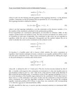
Then a nonlinear tracking controller for high-speed solenoid valve can be designed to follow
the expected movable parts position of solenoid valve. However, the practical actuator has
magnitude and rate limitations. The maximum adjustable open area of the valve is 7.4mm
2
and switch frequency is 100Hz. So the optimal performance is not achievable.
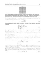
Fig. 6. Shock Absorber Efficiency and Control Input Comparison w/o Input Constraints
From the above figures, we can see that the high-speed solenoid valve’s limited rate and
magnitude have negative effects on the shock absorber if those input constraints are not
considered during the controller synthesis process.
4.2 Nonlinear Predictive Controller
Model predictive control (MPC) is suitable for constrained, digital control problems. Initially
MPC has been widely used in the industrial processes with linear models, but recently some
researchers have tried to apply MPC to other fields like automotive and aerospace, and the
nonlinear model is used instead of linear one due to the increasingly high demands on
better control performance. However, optimization is a difficult task for nonlinear model
predictive control (NMPC) problem. Generally a standard nonlinear programming method
such as SQP is used. But it is the non-convex optimization method for constrained nonlinear
problem, thus global optimum can not be obtained. Furthermore, due to its high
computational requirement, SQP method is not suitable for online optimization.
To the semi-active landing gear control problem, a nonlinear output-tracking predictive
control approach (Lu, 1998) is adopted here considering its effectiveness to constrained
control problems and real-time performance. The basic principle of this control approach is
to get a nonlinear feedback control law by solving an approximate receding-horizon control
problem via a multi-step predictive control formulation.
The nonlinear state equation and output equation are defined by eq. (28-29). And the
following receding-horizon problem can be set up for providing the output-tracking control:
duueeutt
Tt
t
TT
uu
)]()()()([
2
1
min],),([min RQxJ
(31)
subject to the state equations (28) and
0)(
Tte
(32)
where
)()()( tytyte
d
.
Then we shall approximate the above receding-horizon control problem by the following
multi-step-ahead predictive control formulation. Define
NTh /
, with
N
is control
number during the prediction horizon. The output
)( khty
is approximated by the first-
order Taylor series expansion
Nktkhtttykhty
1)},()()]{([)()( xxxC
(33)
where
xxcC
/)(
. The desired output
)( khty
d
is predicted similarly by recursive
first-order Taylor series expansions
)()()( tyhtyhty
ddd
)]()([)()()()()2( tyhtyhtyhtyhtyhhtyhty
ddddddd
where another first-order expansion
)()()( tyhtyhty
ddd
, then we have
])()1([)()(
1
0
k
i
d
i
dd
tpyhphtykhty
(34)
where
dtdp /
is the differentiation operator. Combining the predictions of )( khty
and
)( khty
d
, we obtain the prediction of the tracking error
Model Predictive Control294
})]()1())1(()([
])([{)()()(
1
0
1
0
k
i
d
ii
k
i
i
d
tpyhphiktuhIC
hhkhtykhtykhte
gF
fFIC
(35)
where
xxfxF
/)()(
. Approximating the cost function by the trapezoidal rule, it can be
written as a quadratic function
),,()()(
2
1
d
TT
ye xqvxrvxHvJ
(36)
where
]})1([), ,(),({ hNtuhtutucol
v
.
The constraint (eq. (32)) is then expressed as
0)(
Nhte
which leads to
),,()(
d
T
ye xdvxM
(37)
where
],)(,,)[(
1
ggFIgFICM hh
NT
(38)
1
0
)]()1()([
1
N
i
d
ii
tpyhphe
h
fFICd
(39)
Now the output-tracking receding-horizon optimal control problem is reduced to the
problem of minimizing
J
with respect to
v
subject to eq. (37), which is a quadratic
programming problem. The closed-form optimal solution for this problem is
dMHMMHrHMMHMMHHv ])([])([
11111111
TTT
(40)
Then the closed-loop nonlinear predictive output-tracking control law is
)1(),;( vx
Ntu
(41)
Unlike the input-output feedback linearization control laws, the existence of the proposed
nonlinear predictive output-tracking control does not depend on the requirement that the
system have a relative degree. And more important, the actuator’s amplitude and rate
constraints can be taken into account during the controller synthesis process.
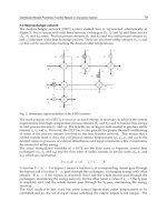
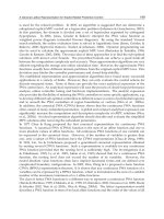
4.3 Numerical Simulation
Based on the analysis described in previous sections, the numerical simulation of the semi-
active landing gear system responses are derived using MATLAB environment. The
prototype of the simulation model is a semi-active landing gear comprehensive
experimental platform we built, which can be reconfigured to accomplish tasks such as drop
tests, taxi tests and shimmy tests. The sprung mass of this system is 405kg and the
unsprung mass is 15kg. The other parameters of the simulation model can be found in (Wu
et al, 2007). Fig.7 is the photo of the experiment system.
Fig. 7. Landing gear experiment platform
Three kinds of control methods including passive control, inverse dynamics semi-active
control and nonlinear predictive semi-active control are used in the computer simulation.
The fixed size of oil orifice for passive control is optimized manually under following
parameters: sinking speed is 2 m/s and aircraft sprung mass is 405 kg. In the process of
simulation, the sprung mass remains constant and the comparison is taken in terms of
different sinking speed: 1.5 m/s, 2 m/s and 2.5 m/s. For passive control, the orifice size is
fixed. From the Figs. 8-10 and Table 1, when system parameters such as sinking speed
change, the control performance of the passive control decreases greatly, for the fixed orifice
size in passive control is designed under standard condition.
Fig. 8. Efficiency Comparison under Normal Condition
Nonlinear Predictive Control of Semi-Active Landing Gear 295
})]()1())1(()([
])([{)()()(
1
0
1
0
k
i
d
ii
k
i
i
d
tpyhphiktuhIC
hhkhtykhtykhte
gF
fFIC
(35)
where
xxfxF
/)()(
. Approximating the cost function by the trapezoidal rule, it can be
written as a quadratic function
),,()()(
2
1
d
TT
ye xqvxrvxHvJ
(36)
where
]})1([), ,(),({ hNtuhtutucol
v
.
The constraint (eq. (32)) is then expressed as
0)(
Nhte
which leads to
),,()(
d
T
ye xdvxM
(37)
where
],)(,,)[(
1
ggFIgFICM hh
NT
(38)
1
0
)]()1()([
1
N
i
d
ii
tpyhphe
h
fFICd
(39)
Now the output-tracking receding-horizon optimal control problem is reduced to the
problem of minimizing
J
with respect to
v
subject to eq. (37), which is a quadratic
programming problem. The closed-form optimal solution for this problem is
dMHMMHrHMMHMMHHv ])([])([
11111111
TTT
(40)
Then the closed-loop nonlinear predictive output-tracking control law is
)1(),;( vx
Ntu
(41)
Unlike the input-output feedback linearization control laws, the existence of the proposed
nonlinear predictive output-tracking control does not depend on the requirement that the
system have a relative degree. And more important, the actuator’s amplitude and rate
constraints can be taken into account during the controller synthesis process.
4.3 Numerical Simulation
Based on the analysis described in previous sections, the numerical simulation of the semi-
active landing gear system responses are derived using MATLAB environment. The
prototype of the simulation model is a semi-active landing gear comprehensive
experimental platform we built, which can be reconfigured to accomplish tasks such as drop
tests, taxi tests and shimmy tests. The sprung mass of this system is 405kg and the
unsprung mass is 15kg. The other parameters of the simulation model can be found in (Wu
et al, 2007). Fig.7 is the photo of the experiment system.
Fig. 7. Landing gear experiment platform
Three kinds of control methods including passive control, inverse dynamics semi-active
control and nonlinear predictive semi-active control are used in the computer simulation.
The fixed size of oil orifice for passive control is optimized manually under following
parameters: sinking speed is 2 m/s and aircraft sprung mass is 405 kg. In the process of
simulation, the sprung mass remains constant and the comparison is taken in terms of
different sinking speed: 1.5 m/s, 2 m/s and 2.5 m/s. For passive control, the orifice size is
fixed. From the Figs. 8-10 and Table 1, when system parameters such as sinking speed
change, the control performance of the passive control decreases greatly, for the fixed orifice
size in passive control is designed under standard condition.
Fig. 8. Efficiency Comparison under Normal Condition
Model Predictive Control296
Conventional passive landing gear is especially optimized for heavy landing load condition,
so the passive landing gear behaves even worse under light landing load condition. The
performance of semi-active control is superior to that of passive one due to its tunable
orifice size and nonlinear predictive semi-active control method has the best performance of
all. Due to its continuous online compensation and consideration of actuator’s constraints,
nonlinear predictive semi-active control method can both increase the efficiency of shock
absorber and make the output smoother during the control interval, which can effectively
alleviate the fatigue damage of both airframe and landing gear.
Fig. 9. Efficiency Comparison under Light Landing Load Condition
Fig. 10. Efficiency Comparison under Heavy Landing Load Condition
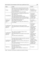
Control Method Passive Semi-Active IDC Semi-Active Predictive
Efficiency/(
1
0.2
sm
)
0.8483 0.8788 0.9048
Efficiency/(
1
5.1
sm
)
0.8449 0.8739 0.9036
Efficiency/(
1
5.2
sm
)
0.8419 0.8554 0.8813
Table 1. Comparison of shock absorber efficiency
4.4 Sensitivity Analysis
Sometimes system parameters such as sinking speed, sprung weight and attitude of aircraft
at touch down may be measured or estimated with errors, which will lead to bias of
estimation for optimal target load. But the controller should behave robust to withstand
certain measurement or estimation errors within reasonable scope so that the airframe will
not suffer from large vertical load at touch down.
Simulation of sensitivity analysis is conducted under the standard condition controller
design: sinking speed is 2 m/s and aircraft sprung mass is 405 kg, introducing 10% errors
for sinking speed and sprung mass individually. The actual sinking speed is measured by
avionic equipments and the aircraft sprung mass is estimated by considering the weights of
oil, cargo and passengers. The measurement and estimation errors will be less than the
assumed maximal one.
From the above Figs.11,12 simulation results, it can seen that the reasonable measuring error
of sinking speed has little effect on the performance of nonlinear predictive semi-active
controller, whilst estimating error of sprung mass has side effect to the control performance
and shock absorber efficiency decreases a little. To further improve the performance under
mass estimating error, it is possible to either simply introduce measurement of aircraft mass
or develop robust controller which is non-sensitive to estimating the error of aircraft sprung
mass.
Fig. 11. Sensitivity to sink speed measuring error
Fig. 12. Sensitivity to sprung mass estimating error
Nonlinear Predictive Control of Semi-Active Landing Gear 297
Conventional passive landing gear is especially optimized for heavy landing load condition,
so the passive landing gear behaves even worse under light landing load condition. The
performance of semi-active control is superior to that of passive one due to its tunable
orifice size and nonlinear predictive semi-active control method has the best performance of
all. Due to its continuous online compensation and consideration of actuator’s constraints,
nonlinear predictive semi-active control method can both increase the efficiency of shock
absorber and make the output smoother during the control interval, which can effectively
alleviate the fatigue damage of both airframe and landing gear.
Fig. 9. Efficiency Comparison under Light Landing Load Condition
Fig. 10. Efficiency Comparison under Heavy Landing Load Condition
Control Method Passive Semi-Active IDC Semi-Active Predictive
Efficiency/(
1
0.2
sm
)
0.8483 0.8788 0.9048
Efficiency/(
1
5.1
sm
)
0.8449 0.8739 0.9036
Efficiency/(
1
5.2
sm
)
0.8419 0.8554 0.8813
Table 1. Comparison of shock absorber efficiency
4.4 Sensitivity Analysis
Sometimes system parameters such as sinking speed, sprung weight and attitude of aircraft
at touch down may be measured or estimated with errors, which will lead to bias of
estimation for optimal target load. But the controller should behave robust to withstand
certain measurement or estimation errors within reasonable scope so that the airframe will
not suffer from large vertical load at touch down.
Simulation of sensitivity analysis is conducted under the standard condition controller
design: sinking speed is 2 m/s and aircraft sprung mass is 405 kg, introducing 10% errors
for sinking speed and sprung mass individually. The actual sinking speed is measured by
avionic equipments and the aircraft sprung mass is estimated by considering the weights of
oil, cargo and passengers. The measurement and estimation errors will be less than the
assumed maximal one.
From the above Figs.11,12 simulation results, it can seen that the reasonable measuring error
of sinking speed has little effect on the performance of nonlinear predictive semi-active
controller, whilst estimating error of sprung mass has side effect to the control performance
and shock absorber efficiency decreases a little. To further improve the performance under
mass estimating error, it is possible to either simply introduce measurement of aircraft mass
or develop robust controller which is non-sensitive to estimating the error of aircraft sprung
mass.
Fig. 11. Sensitivity to sink speed measuring error
Fig. 12. Sensitivity to sprung mass estimating error
Model Predictive Control298
5. Semi-Active Predictive Controller Design for Taxiing Phase
In this section, we will propose a nonlinear predictive controller incorporating radial basis
function network (RBF) and backstepping design methodology (Kristic et al., 1995) for semi-
active controlled landing gear during aircraft taxiing.
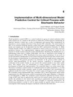
5.1 Hierarchical Controller Structure
A hierarchical control structure which contains three control loops is adopted here. The
outer loop determines the expected strut force of the semi-active shock absorber. At
touchdown phase and taxiing phase, the computation of the expected strut force will be
different due to different design objective. The middle loop is responsible for controlling of
solenoid valve’s mechanical and magnetic dynamics. The high speed solenoid valve
contains high nonlinearity and can not be regulated by traditional linear controller i.e. PID.
We develop a RBF network to approximate the nonlinear dynamics which can not be
precisely modelled and adopt backstepping, a constructive nonlinear control design method
to stabilize the whole nonlinear system. The inner loop is the current loop. It ensures stable
tracking of commanded current that middle loop outputs.
Fig. 13. Hierarchical Controller Structure
5.2 Background for RBF network
A RBF network is typically comprised of a layer of radial basis activation functions with an
associated Euclidean input mapping. The output is then taken as a linear activation function
with an inner product or weighted average input mapping.
In this paper, we use a weighted average mapping in the output node. The input-output
relationship in a RBF with
T
n
xx ],,[
1
x as an input is given by
)(
)/exp(
)/exp(
),(
1
2
2
1
2
2
xξθ
x
x
θx
T
m
i
i
m
i
ii
c
cw
(42)
where
T
n
ww ],,[
1
θ
(43)
m
i
i
i
i
c
c
1
2
2
2
2
)/exp(
)/exp(
x
x
(44)
The RBF network is a good approximator for general nonlinear function. For a nonlinear
function FN, we can express it using RBF network with the following form,
ξθξθξθ
TTT
N
F
~
ˆ
(45)
where θ is the vector of tunable parameters under ideal approximation condition,
θ
ˆ
under
practical approximation condition,
θ
~
parameter approximation error, ε function
reconstruction error.
5.3 Outer Loop Design
The function of the outer control loop is to produce a target strut force for semi-active shock
absorber by using active control law. Then middle loop and inner loop controller will be
designed to approximate the optimal performance that active controller achieves.
(a) Skyhook Controller
At the taxiing phase, the landing gear system acts like the suspension of ground vehicle. So
we first adopt the most widely used active suspension control approach – the skyhook
controller. At this control scheme the actuator generates a control force which is
proportional to the sprung mass vertical velocity. The equation of skyhook controller can be
expressed as the following form:
)()(
4211
xxCxxKF
skydskysky
(46)
In order to blend out low frequency components of the vertical velocity signal which results
from the aircraft taxiing on sloped runways or long bumps, we modify it by adding high
pass filter to the skyhook controller.
1
x
ws
s
x
k
s
(47)
where
k
w
is roll off frequency of high pass filter. Thus we get the desired strut force.
sHPskydskyd
xKxxCxxKF )()(
4211
(48)
where
HP
K
is a constant scale factor.
Nonlinear Predictive Control of Semi-Active Landing Gear 299
5. Semi-Active Predictive Controller Design for Taxiing Phase
In this section, we will propose a nonlinear predictive controller incorporating radial basis
function network (RBF) and backstepping design methodology (Kristic et al., 1995) for semi-
active controlled landing gear during aircraft taxiing.
5.1 Hierarchical Controller Structure
A hierarchical control structure which contains three control loops is adopted here. The
outer loop determines the expected strut force of the semi-active shock absorber. At
touchdown phase and taxiing phase, the computation of the expected strut force will be
different due to different design objective. The middle loop is responsible for controlling of
solenoid valve’s mechanical and magnetic dynamics. The high speed solenoid valve
contains high nonlinearity and can not be regulated by traditional linear controller i.e. PID.
We develop a RBF network to approximate the nonlinear dynamics which can not be
precisely modelled and adopt backstepping, a constructive nonlinear control design method
to stabilize the whole nonlinear system. The inner loop is the current loop. It ensures stable
tracking of commanded current that middle loop outputs.
Fig. 13. Hierarchical Controller Structure
5.2 Background for RBF network
A RBF network is typically comprised of a layer of radial basis activation functions with an
associated Euclidean input mapping. The output is then taken as a linear activation function
with an inner product or weighted average input mapping.
In this paper, we use a weighted average mapping in the output node. The input-output
relationship in a RBF with
T
n
xx ],,[
1
x as an input is given by
)(
)/exp(
)/exp(
),(
1
2
2
1
2
2
xξθ
x
x
θx
T
m
i
i
m
i
ii
c
cw
(42)
where
T
n
ww ],,[
1
θ
(43)
m
i
i
i
i
c
c
1
2
2
2
2
)/exp(
)/exp(
x
x
(44)
The RBF network is a good approximator for general nonlinear function. For a nonlinear
function FN, we can express it using RBF network with the following form,
ξθξθξθ
TTT
N
F
~
ˆ
(45)
where θ is the vector of tunable parameters under ideal approximation condition,
θ
ˆ
under
practical approximation condition,
θ
~
parameter approximation error, ε function
reconstruction error.
5.3 Outer Loop Design
The function of the outer control loop is to produce a target strut force for semi-active shock
absorber by using active control law. Then middle loop and inner loop controller will be
designed to approximate the optimal performance that active controller achieves.
(a) Skyhook Controller
At the taxiing phase, the landing gear system acts like the suspension of ground vehicle. So
we first adopt the most widely used active suspension control approach – the skyhook
controller. At this control scheme the actuator generates a control force which is
proportional to the sprung mass vertical velocity. The equation of skyhook controller can be
expressed as the following form:
)()(
4211
xxCxxKF
skydskysky
(46)
In order to blend out low frequency components of the vertical velocity signal which results
from the aircraft taxiing on sloped runways or long bumps, we modify it by adding high
pass filter to the skyhook controller.
1
x
ws
s
x
k
s
(47)
where
k
w
is roll off frequency of high pass filter. Thus we get the desired strut force.
sHPskydskyd
xKxxCxxKF )()(
4211
(48)
where
HP
K
is a constant scale factor.
Model Predictive Control300
(b) Nonlinear Predictive Controller
Compare with traditional skyhook controller, model predictive controller is more suitable
for constrained nonlinear system like landing gear system or suspension system. Input and
state constraints can be incorporated into the performance index to achieve best
performance.
The system model of outer loop controller is eq. (16-19), which can be expressed as follows:
daaa
F)()( xgxfx
(49)
where
],,,[
4321
xxxx
a
x
,
d
F
is the control input and the output equation is
1
xy
. Then
a similar receding-horizon problem can be set up for providing the output-tracking control:
dFFeeFtt
Tt
t
da
T
daa
T
a
F
da
F
dd
)]()()()([
2
1
min],),([min RQxJ
(50)
subject to the state equations (49) and
0)(
Tte
a
(51)
where
)()()(
11
txtxte
da
.
Following a similar synthesis process as in section 4.2, we can get a closed-loop nonlinear
predictive output-tracking control law to achieve approximate optimal active control
performance.
5.4 RBF-based Backstepping Design (Middle Loop)
In this section we propose a RBF-based backstepping method to complete the design of the
semi-active controller. Stability proofs are given.
First we define the force tracking error as
FFe
d
1
. Differentiate and substitute from Eq.
(16-25),
1
3
2
2 5
2 2
5
5 5
3
2 2
2 2
5 5
0
0 1
1 0 1
1 2 5 6 1 1 2 3 4 5
[(1 ) ]
( )
2( ) 1 ( / )
( ) 1 ( / )
(1 ) [ ( ) ]
( , ) ( , , , , )
d d m air oil
o
d
v d v o
o
v d v o
n
m i a a
a
d
d
e F F F K F F
dt
A
d
F x x
dx
K x C K x A
A
x x
K x C K x A
V
d
K P A P A x
dx V A x
F G x x x H x x x x x
where
),(
521
xxG
,
),,,,(
54321
xxxxxH
is the nonlinear functions related to the strut
dynamics.
(a) First Step
Select the desired solenoid valve movable part velocity as
)(
111
1
16
ekFHGx
dd
(52)
where
1
k
is a design parameter. Then we get
1121111121
543211252165211
)(
),,,,(),(),(
ekeGHekFHeGF
xxxxxHexxGxxxGFe
dd
dd
where
d
xxe
662
.
Consider the following Lyapunov function candidate
2
11
2
1
eV
Differentiate
1
V
, thus we get
2
1121111
ekGeeeeV
(b) Second Step
6
x
is not the true control input. We then choose
2
7
xu
as virtual input.
Differentiate
2
e
, we get
WHx
m
C
uGxxe
v
s
d
262662
where
v
mxBG /)(
52
,
dv
xmfH
62
/
and
vfs
mfxKKW /])[(
05
.
Consider the following Lyapunov function candidate
)
~~
(
2
1
)
~~
(
2
1
2
1
2
1
221
1
11
2
212
θΓθθΓθ
TT
trtreVV
where
1
and
2
are positive definite matrices. Differentiate
2
V
)
~~
()
~~
()(
2
1
221
1
11262212
θΓθθΓθ
TT
v
s
trtrWHx
m
C
uGeVV
Then we choose the control input:
Nonlinear Predictive Control of Semi-Active Landing Gear 301
(b) Nonlinear Predictive Controller
Compare with traditional skyhook controller, model predictive controller is more suitable
for constrained nonlinear system like landing gear system or suspension system. Input and
state constraints can be incorporated into the performance index to achieve best
performance.
The system model of outer loop controller is eq. (16-19), which can be expressed as follows:
daaa
F)()( xgxfx
(49)
where
],,,[
4321
xxxx
a
x
,
d
F
is the control input and the output equation is
1
xy
. Then
a similar receding-horizon problem can be set up for providing the output-tracking control:
dFFeeFtt
Tt
t
da
T
daa
T
a
F
da
F
dd
)]()()()([
2
1
min],),([min RQxJ
(50)
subject to the state equations (49) and
0)(
Tte
a
(51)
where
)()()(
11
txtxte
da
.
Following a similar synthesis process as in section 4.2, we can get a closed-loop nonlinear
predictive output-tracking control law to achieve approximate optimal active control
performance.
5.4 RBF-based Backstepping Design (Middle Loop)
In this section we propose a RBF-based backstepping method to complete the design of the
semi-active controller. Stability proofs are given.
First we define the force tracking error as
FFe
d
1
. Differentiate and substitute from Eq.
(16-25),
1
3
2
2 5
2 2
5
5 5
3
2 2
2 2
5 5
0
0 1
1 0 1
1 2 5 6 1 1 2 3 4 5
[(1 ) ]
( )
2( ) 1 ( / )
( ) 1 ( / )
(1 ) [ ( ) ]
( , ) ( , , , , )
d d m air oil
o
d
v d v o
o
v d v o
n
m i a a
a
d
d
e F F F K F F
dt
A
d
F x x
dx
K x C K x A
A
x x
K x C K x A
V
d
K P A P A x
dx V A x
F G x x x H x x x x x
where
),(
521
xxG
,
),,,,(
54321
xxxxxH
is the nonlinear functions related to the strut
dynamics.
(a) First Step
Select the desired solenoid valve movable part velocity as
)(
111
1
16
ekFHGx
dd
(52)
where
1
k
is a design parameter. Then we get
1121111121
543211252165211
)(
),,,,(),(),(
ekeGHekFHeGF
xxxxxHexxGxxxGFe
dd
dd
where
d
xxe
662
.
Consider the following Lyapunov function candidate
2
11
2
1
eV
Differentiate
1
V
, thus we get
2
1121111
ekGeeeeV
(b) Second Step
6
x
is not the true control input. We then choose
2
7
xu
as virtual input.
Differentiate
2
e
, we get
WHx
m
C
uGxxe
v
s
d
262662
where
v
mxBG /)(
52
,
dv
xmfH
62
/
and
vfs
mfxKKW /])[(
05
.
Consider the following Lyapunov function candidate
)
~~
(
2
1
)
~~
(
2
1
2
1
2
1
221
1
11
2
212
θΓθθΓθ
TT
trtreVV
where
1
and
2
are positive definite matrices. Differentiate
2
V
)
~~
()
~~
()(
2
1
221
1
11262212
θΓθθΓθ
TT
v
s
trtrWHx
m
C
uGeVV
Then we choose the control input:
Model Predictive Control302
)
ˆ
(
ˆ
112262
1
2
eGekWx
m
C
HGu
d
v
s
(53)
where
2
k is a design parameter,
112
ˆˆ
ξθ
T
G
is the estimation of
),(
522
xxG
,
222
ˆ
ˆ
ξθ
T
H
is the
estimation of
),,,,(
54321
xxxxxH
. Thus we get
)]
ˆ
(
~
[)]
ˆ
(
~
[
~~~~
)
~~
()
~~
(
~
~
222
1
22211
1
11
112221222222222112221121
2
1
221
1
1111222222222122212
etruetr
eGeeuee
m
C
ekeeueeueV
trtreGeekeeHee
m
C
ueuGeVV
TT
v
s
TT
v
s
ξθΓθξθΓθ
ξθξθξθξθ
θΓθθΓθ
Choose the tuning law as:
2111
ˆ
ueξΓθ
,
2222
ˆ
eξΓθ
(54)
So we have
0
4
)/(
)
2
/
(
2
2
21
2
2
21
22
2
11
1
2212212
2
22
2
112112
k
mCu
k
mCu
ekek
euee
m
C
eGeekekeGeV
vsvs
v
s
Therefore, the system is stable and the error will asymptotically converge to zero.
5.5 Inner Loop Design
The function of the inner loop is to precisely tracking of solenoid valve’s current. We apply a
simple proportional control to the electrical dynamics as follows
)()(
777
xuKxxKV
cdc
(55)
where
c
K
is the controller gain.
The above three control loops represent different time scales. The fastest is the inner loop
due to its electrical characteristics. The next is the middle loop. It is faster than the outer loop
because the controlled moving part’s inertial of the middle loop is much smaller than that of
the outer loop.
5.6 Numerical Simulation
After touchdown, the taxiing process will last relatively a long time before aircraft stops. To
simulate the road excitation of runway and taxiway, a random velocity excitation signal
)(tw
is introduced into Eq. (18).
)(
43
twxx
(56)
The simulation result is compared using airframe vertical displacement, which is one of the
most important criterion for taxiing condition. Due to lack of self-tuning capability, the
passive landing gear does not behave well and passes much of the road excitation to the
airframe. That will be harmful for the aircraft structure and meanwhile make passages
uncomfortable. The proposed semi-active landing gear effectively filters the unfriendly road
excitation as we wish.
Fig. 14. System Response Comparison under Random Input
From the simulation results of both aircraft touch-down and taxiing conditions, we can see
that the proposed semi-active controller gives the landing gear system extra flexibility to
deal with the unknown and uncertain external environment. It will make the modern
aircraft system being more intelligent and robust.
6. Conclusion
The application of model predictive control and constructive nonlinear control methodology
to semi-active landing gear system is studied in this paper. A unified shock absorber
mathematical model incorporates solenoid valve’s electromechanical and magnetic
dynamics is built to facilitate simulation and controller design. Then we propose a
hierarchical control structure to deal with the high nonlinearity. A dual mode model
predictive controller as an outer loop controller is developed to generate the ideal strut force
on both touchdown and taxiing phase. And a systematic adaptive backstepping design
method is used to stabilize the whole system and track the reference force in the middle and
inner loop. Simulation results show that the proposed control scheme is superior to the
traditional control methods.
Nonlinear Predictive Control of Semi-Active Landing Gear 303
)
ˆ
(
ˆ
112262
1
2
eGekWx
m
C
HGu
d
v
s
(53)
where
2
k is a design parameter,
112
ˆˆ
ξθ
T
G
is the estimation of
),(
522
xxG
,
222
ˆ
ˆ
ξθ
T
H
is the
estimation of
),,,,(
54321
xxxxxH
. Thus we get
)]
ˆ
(
~
[)]
ˆ
(
~
[
~~~~
)
~~
()
~~
(
~
~
222
1
22211
1
11
112221222222222112221121
2
1
221
1
1111222222222122212
etruetr
eGeeuee
m
C
ekeeueeueV
trtreGeekeeHee
m
C
ueuGeVV
TT
v
s
TT
v
s
ξθΓθξθΓθ
ξθξθξθξθ
θΓθθΓθ
Choose the tuning law as:
2111
ˆ
ueξΓθ
,
2222
ˆ
eξΓθ
(54)
So we have
0
4
)/(
)
2
/
(
2
2
21
2
2
21
22
2
11
1
2212212
2
22
2
112112
k
mCu
k
mCu
ekek
euee
m
C
eG
eekekeGeV
vsvs
v
s
Therefore, the system is stable and the error will asymptotically converge to zero.
5.5 Inner Loop Design
The function of the inner loop is to precisely tracking of solenoid valve’s current. We apply a
simple proportional control to the electrical dynamics as follows
)()(
777
xuKxxKV
cdc
(55)
where
c
K
is the controller gain.
The above three control loops represent different time scales. The fastest is the inner loop
due to its electrical characteristics. The next is the middle loop. It is faster than the outer loop
because the controlled moving part’s inertial of the middle loop is much smaller than that of
the outer loop.
5.6 Numerical Simulation
After touchdown, the taxiing process will last relatively a long time before aircraft stops. To
simulate the road excitation of runway and taxiway, a random velocity excitation signal
)(tw
is introduced into Eq. (18).
)(
43
twxx
(56)
The simulation result is compared using airframe vertical displacement, which is one of the
most important criterion for taxiing condition. Due to lack of self-tuning capability, the
passive landing gear does not behave well and passes much of the road excitation to the
airframe. That will be harmful for the aircraft structure and meanwhile make passages
uncomfortable. The proposed semi-active landing gear effectively filters the unfriendly road
excitation as we wish.
Fig. 14. System Response Comparison under Random Input
From the simulation results of both aircraft touch-down and taxiing conditions, we can see
that the proposed semi-active controller gives the landing gear system extra flexibility to
deal with the unknown and uncertain external environment. It will make the modern
aircraft system being more intelligent and robust.
6. Conclusion
The application of model predictive control and constructive nonlinear control methodology
to semi-active landing gear system is studied in this paper. A unified shock absorber
mathematical model incorporates solenoid valve’s electromechanical and magnetic
dynamics is built to facilitate simulation and controller design. Then we propose a
hierarchical control structure to deal with the high nonlinearity. A dual mode model
predictive controller as an outer loop controller is developed to generate the ideal strut force
on both touchdown and taxiing phase. And a systematic adaptive backstepping design
method is used to stabilize the whole system and track the reference force in the middle and
inner loop. Simulation results show that the proposed control scheme is superior to the
traditional control methods.
Model Predictive Control304
7. References
Batterbee, D.; Sims, N. & Stanway, R. (2007). Magnetorheological landing gear: 1. a design
methodology. Smart Materials and Structures, Vol. 16, pp. 2429-2440.
Ghiringhelli, L. G. (2000). Testing of semiactive landing gear control for a general aviation
aircraft. Journal of Aircraft, Vol.7, No.4, pp.606-616.
Ghiringhelli, L. G. & Gualdi, S. (2004). Evaluation of a landing gear semi-active control
system for complete aircraft landing. Aerotecnica Missili e Spazio, No. 6, pp. 21-31.
Hyochoong, B.& Choong-Seok, O. (2004). Predictive control for the attitude maneuver of a
flexible spacecraft. Aerospace Science and Technology, Vol. 8, No. 5, pp. 443-452.
Karnopp, D. (1983). Active damping in road vehicle suspension systems. Vehicle System
Dynamics, Vol.12, No. 6, pp.291-316.
Kristic, M.; Kanellakopoulos, I. & Kokotovic, P.V. (1995). Nonlinear and Adaptive Control
Design, Wiley-Interscience, ISBN: 978-0-471-12732-1, USA.
Krüger,W. (2000). Integrated design process for the development of semi-active landing
gears for transport aircraft, PhD thesis, University of Stuttgart.
Liu, H.; Gu, H. B. & Chen, D. W. (2008). Application of high-speed solenoid valve to the
semi-active control of landing gear. Chinese Journal of Aeronautics, Vol.21, No.3,
pp.232-240.
Liu, H. & Gu, H. B. (2008). Nonlinear model for a high-speed solenoid valve and its
simulation. Mechanical Science and Technology for Aerospace Engineering, Vol.27, No.7,
pp.866-870.
Lou, Z.; Ervin, R. & Winkler, C. (1993). An electrorheologically controlled semi-active
landing gear. SAE Paper931403.
Lu, P. (1998). Approximate nonlinear receding-horizon control laws in closed form.
International Journal of Control, Vol. 71, No.1, pp.19-34.
Maemori, K.; Tanigawa, N. & Koganei R (2003). Optimization of a semi-active shock
absorber for aircraft landing gear, Proceedings of ASME Design Engineering Technical
Conference, pp.597-603.
Malaguti, F. & Pregnolato, E. (2002). Proportional control of on/off solenoid operated
hydraulic valve by nonlinear robust controller, Proceedings of IEEE International
Symposium on Industrial Electronics, pp.415-419.
Mehra, R. K.; Amin, J. N. & Hedrick, K. J. (1997). Active suspension using preview
information and model predictive control, Proceedings of the 1997 IEEE International
Conference on Control Applications, pp. 860-865.
Michael, A. H. (1998). Nonlinear model predictive control: current status and future
direction. Computers and Chemical Engineering, Vol.23, pp.187-202.
Mikulowski, G. & LeLetty, R. (2008). Advanced landing gears for improved impact
absorption, Proceedings of the 11th International conf. on New Actuators, pp.175-194.
Slotine, J.E. & Li, W.P. (1991). Applied Nonlinear Control, Prentice Hall, ISBN: 0-13-040890-5,
USA.
Wang, X. M. & Carl U. (1999). Fuzzy control of aircraft semi-active landing gear system,
AIAA 37th Aerospace Sciences Meeting and Exhibit.
Wu, D. S.; Gu, H.B.; Liu, H. (2007). GA-based model predictive control of semi-active
landing gear. Chinese Journal of Aeronautics, Vol.20, No.1, pp.47-54.
Yadav, D. & Ramamoorthy, R. P. (1991). Nonlinear landing gear behavior at touchdown.
Journal of Dynamic Systems, Measurement and Control, Vol.113, No.12, pp.677-683.