Model Predictive Control Part 12 doc
Bạn đang xem bản rút gọn của tài liệu. Xem và tải ngay bản đầy đủ của tài liệu tại đây (662.33 KB, 20 trang )
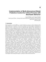
Plasma stabilization system design on the base of model predictive control 213
Now let us show how introced areas C
∆1
and C
∆2
are related to the standart areas on the
complex plane, which are commonly used in the analysis and synthesis of the continuos time
systems.
Primarily, it may be noticed that the eigenvalues of the continues linear model and the discrete
linear model are connected by the following rule (Hendricks et al., 2008): if s is the eigenvalue
of the continuos time system matrix, then z
= e
sT
is the correspondent eigenvalue of the
discrete time system matrix, where T is the sampling period. Taking into account this relation,
let consider the examples of the mapping of some standart areas for continuous systems to the
areas for discrete systems.
Example 1 Let we have given area C
= {s = x ± yj ∈ C
1
: x ≤ −α}, depicted in Fig. 3. It is
evident that the points of the line x
= −α are mapped to the points of the circle |z | = e
−αT
.
The area C itself is mapped on the disc
|z| ≤ e
−αT
, as shown in Fig.3. This disc corresponds to
the area C
∆1
, which defines the degree of stability for discrete system.
Fig. 3. The correspondence of the areas for continuous and discrete system
Example 2 Consider the area
C
= {s = x ± yj ∈ C
1
: x ≤ −α, 0 ≤ y ≤ (−x − α)tgβ},
depicted in Fig. 4, where 0
≤ β <
π
2
and α > 0 is a given real numbers.
Let perform the mapping of the area C on the z-plane. It is evident that the vertex of the angle
(−α, 0) is mapped to the point with polar coordinates r = e
−αT
, ϕ = 0 on the plane z. Let now
map each segment from the set
L
γ
= {s = x ± yj ∈ C
1
: x = γ, γ ≤ −α, 0 ≤ y ≤ (−γ − α)tgβ}
to the z-plane. Each point s = γ ± yj of the segment L
γ
is mapped to the point z = e
sT
=
e
γT±jyT
on the plane z. Therefore, the points of the segment L
γ
are mapped to the arc of the
circle with radius e
γT
if the following condition holds −α − π/(Ttgβ) < γ ≤ −α, and to the
whole circle if γ
≤ −α − π/(Ttgβ). Therefore, the maximum radius of the circle, which is
fullfilled by the points of the segment, is equal to r
= e
−αT−π/tgβ
, corresponding with the
equality γ
0
= −α − π/(Ttgβ). Notice that the rays, which constitutes the angle, mapped to
the logarithmic spirals. Moreover, the bound of the area on the plane z is formed by the arcs
of these spirals in accordace with the x varying from
−α to γ
0
.
Fig. 4. The correspondence of the areas for continuous and discrete time systems
Let introduce the notation ρ
= e
xT
, and define the function ψ(ρ), which represents the con-
straints on the argument values while the radius ρ of the circle is fixed:
ψ
(ρ) =
(−lnρ − αT)tgβ, i f ρ ∈ [r
, r],
π, i f ρ
∈ [0, r
].
The result of the mapping is shown on the Fig. 4. It can be noted that the obtained area reflects
the desired degree of the discrete time system stability and oscillations.
Let us use the results of the theorem 2 in order to formulate the computational algoritm for the
optimization problem (27) solution on the admissible set Ω
H
taking into account the condition
C
∆
= C
∆2
. It is evident that the first case, where C
∆
= C
∆2
, is a particular case of the second
one.
Consider a real vector γ
∈ E
n
d
and form the polynomial ∆
∗
(z, γ) with the help of formulas
(32),(33),(41). Let require that the tuned parameters of the controller (24), defined by the vector
h
∈ E
r
, provides the identity
∆
(z, h) ≡ ∆
∗
(z, γ), (43)
where ∆
(z, h) is the characteristic polynomial of the closed-loop system with the degree n
d
.
By equating the correspondent coefficients for the same degrees of z-variable, we obtain the
following system of nonlinear equations
L
(h) = χ(γ) (44)
with respect to unknown components of the parameters vector h. The last system has a solu-
tion for any given γ
∈ E
n
d
due to the controller (24) has a full structure. Let consider that, in
general case, the system (44) has a nonunique solution. Then the vector h can be presented as
a set of two vectors h
= {
¯
h, h
c
}, where h
c
∈ E
n
c
is a free component,
¯
h is the vector that is
uniquely defined by the solution of the system (44) for the given vector h
c
.
Let introduce the following notation for the general solution of the system (44)
h
= h
∗
= {
¯
h
∗
(h
c
, γ), h
c
} = h
∗
(γ, h
c
) = h
∗
(),
where
= {γ, h
c
} is a vector of the independent parameters with the dimension λ given by
λ
= dim = dim γ + dim h
c
= n
d
+ n
c
.
Model Predictive Control214
Let form the equations of the prediction model, closed by the controller (24) with the obtained
parameter vector h
∗
˜
x
i+1
= f(
˜
x
i
,
˜
u
i
), i = k + j, j = 0, 1, 2, ,
˜
x
k
= x
k
,
˜
u
i
= r
u
i
+ W(q, h
∗
())C(
˜
x
i
− r
x
i
).
(45)
Now the functional J
k
, which is given by (26) and computed on the solutions of the system
(45), becomes the function of the vector :
J
k
= J
k
(
{
˜
x
i
}, {
˜
u
i
}
)
= J
∗
k
(
W
(
q, h
∗
()
))
= J
∗
k
(). (46)
Theorem 3. Consider the optimization problem (27), where Ω
H
is the admissible set, given by (31),
and the desired area C
∆
= C
∆2
. If the extremum of this problem is achieved at the some point h
k0
∈
Ω
H
, then there exists a vector ∈ E
λ
such that
h
k0
= h
∗
(
k0
), with
k0
= arg min
∈E
λ
J
∗
k
(). (47)
And reversly, if there exists such a vector
k0
∈ E
λ
, that satisfies to the condition (47), then the
following vector h
k0
= h
∗
(
k0
) is the solution of the optimization problem (27). In other words, the
problem (27) is equivalent to the unconstrained optimization problem of the form
J
∗
k
= J
∗
k
() → inf
∈E
λ
. (48)
Proof Assume that the following condition is hold
h
k0
= arg min
h∈Ω
H
J
k
(h), J
k0
= J
k
(h
k0
). (49)
In this case, the characteristic polynomial ∆
(z, h
k0
) of the closed-loop system (28) has the roots
that are located inside the area C
∆2
. Then, accordingly to the theorem 2, it can be found such
a vector γ
= γ
k0
∈ E
n
d
, that ∆(z, h
k0
) ≡ ∆
∗
(z, γ
k0
), where ∆
∗
is a polynomial formed by the
formulas (32), (33). Hence, there exists such a vector
= {γ
k0
, h
k0c
}, for which the following
conditions is hold h
k0
= h
∗
(
k0
), J
∗
k
(
k0
) = J
k0
. Here h
k0c
is the correspondent constituent
part of the vector h
k0
.
Now it is only remain to show that there no exists a vector
01
∈ E
λ
that the condition
J
∗
k
(
01
) < J
k0
is valid. Really, let suppose that such vector exists. But then for the vector
h
∗
(
01
) the following inequality takes place J
k
(h
∗
(
01
) = J
∗
k
(
01
) < J
k0
. But this is not possi-
ble due to the condition (49). The reverse proposition is proved analogously.
Let formulate the computational algorithm in order to get the solution of the optimization
problem (27) on the base of the theorems proved above.
The algorithm consists of the following operations:
1. Set any vector γ
∈ E
n
d
and construct the polynomial ∆
∗
(z, γ) by formulas (32),(33), (41).
2. In accordance with the identity ∆
(z, h) ≡ ∆
∗
(z, γ), form the system of nonlinear equa-
tions
L
(h) = χ(γ), (50)
which has a solution for any vector γ. If the system (50) has a nonunique solution,
assign the vector of the free parameters h
c
∈ E
n
c
.
3. For a given vector
= {γ, h
c
} ∈ E
λ
solve the system of equations (50). As a result,
obtain vector h
∗
().
4. Form the equations of the prediction model closed by the controller (24) with the pa-
rameter vector h
∗
() and compute the value of the cost function J
∗
k
() (46).
5. Solve the problem (48) by using any numerical method for unconstrained minimization
and repeating the steps 3–5.
6. When the optimal solution
k0
= arg min
∈E
λ
J
∗
k
() is found, compute the parameter vector
h
k0
= h
∗
(
k0
) and accept them as a solution.
Now real-time MPC algorithm, which is based on the on-line solution of the problem (27), can
be formulated. This algorithm consists of the following steps:
• Obtain the state estimation
ˆ
x
k
on the base of measurements y
k
.
• Solve the optimization problem (27), using the algorithm stated above, subject to the
prediction model (22) with initial conditions
˜
x
k
=
ˆ
x
k
.
• Let h
k0
be the solution of the problem (27). Implement controller (24) with the parame-
ter vector h
k0
over time interval [kδ, (k + 1)δ], where δ is the sampling period.
• Repeat the whole procedure 1–3 at next time instant
(k + 1) δ.
As a result, let notice the following important features of the proposed MPC-algorithm. For
the first, the linear closed-loop system stability is provided at each sampling interval. Sec-
ondly, the control is realised in the feedback loop. Thirdly, the dimension of the unconstrained
optimization problem is fixed and does not depend on the length of prediction horizon P.
5. Plasma Vertical Stabilization Based on the Model Predictive Control
Let us remember that SISO model (5) represents plasma dynamics in the vertical stabilization
process and limits (6) are imposed on the power supply system. It is necessary to transform
the system (5) to the state-space form for MPC algorithms implementation. Besides that, in
order to take into account the constraint imposed on the current, one more equation should
be added to the model (5). Finally, the linear model of the stabilization process is given by
˙
x
= Ax + bu,
y
= cx + du,
(51)
where x
∈ E
4
and the last component of x corresponds to VS converter current, y =
(
y
1
, y
2
)
∈
E
2
, y
1
is the vertical velocity and y
2
is the current in the VS-converter. We shall assume that
the model (51) describes the process accurately.
We can obtain a linear prediction model in the form (15) by the system (51) discretization. As
a result, we get
˜
x
i+1
= A
d
˜
x
i
+ b
d
˜
u
i
,
˜
x
k
= x
k
,
˜y
i
= C
d
˜
x
i
.
(52)
The constraints (6) form the system of linear inequalities given by
˜
u
i
≤ V
VS
max
, i = k, , k + P − 1;
˜
y
i2
≤ I
VS
max
, i = k + 1, , k + P.
(53)
These constraints define the admissible convex set Ω. The discrete analog of the cost func-
tional (7) with λ
= 1 is given by
J
k
= J
k
( ¯y,
¯
u) =
P
∑
j=1
˜
y
2
k
+j,1
+
˜
u
2
k
+j−1
. (54)
Plasma stabilization system design on the base of model predictive control 215
Let form the equations of the prediction model, closed by the controller (24) with the obtained
parameter vector h
∗
˜
x
i+1
= f(
˜
x
i
,
˜
u
i
), i = k + j, j = 0, 1, 2, ,
˜
x
k
= x
k
,
˜
u
i
= r
u
i
+ W(q, h
∗
())C(
˜
x
i
− r
x
i
).
(45)
Now the functional J
k
, which is given by (26) and computed on the solutions of the system
(45), becomes the function of the vector :
J
k
= J
k
(
{
˜
x
i
}, {
˜
u
i
}
)
= J
∗
k
(
W
(
q, h
∗
()
))
= J
∗
k
(). (46)
Theorem 3. Consider the optimization problem (27), where Ω
H
is the admissible set, given by (31),
and the desired area C
∆
= C
∆2
. If the extremum of this problem is achieved at the some point h
k0
∈
Ω
H
, then there exists a vector ∈ E
λ
such that
h
k0
= h
∗
(
k0
), with
k0
= arg min
∈E
λ
J
∗
k
(). (47)
And reversly, if there exists such a vector
k0
∈ E
λ
, that satisfies to the condition (47), then the
following vector h
k0
= h
∗
(
k0
) is the solution of the optimization problem (27). In other words, the
problem (27) is equivalent to the unconstrained optimization problem of the form
J
∗
k
= J
∗
k
() → inf
∈E
λ
. (48)
Proof Assume that the following condition is hold
h
k0
= arg min
h∈Ω
H
J
k
(h), J
k0
= J
k
(h
k0
). (49)
In this case, the characteristic polynomial ∆
(z, h
k0
) of the closed-loop system (28) has the roots
that are located inside the area C
∆2
. Then, accordingly to the theorem 2, it can be found such
a vector γ
= γ
k0
∈ E
n
d
, that ∆(z, h
k0
) ≡ ∆
∗
(z, γ
k0
), where ∆
∗
is a polynomial formed by the
formulas (32), (33). Hence, there exists such a vector
= {γ
k0
, h
k0c
}, for which the following
conditions is hold h
k0
= h
∗
(
k0
), J
∗
k
(
k0
) = J
k0
. Here h
k0c
is the correspondent constituent
part of the vector h
k0
.
Now it is only remain to show that there no exists a vector
01
∈ E
λ
that the condition
J
∗
k
(
01
) < J
k0
is valid. Really, let suppose that such vector exists. But then for the vector
h
∗
(
01
) the following inequality takes place J
k
(h
∗
(
01
) = J
∗
k
(
01
) < J
k0
. But this is not possi-
ble due to the condition (49). The reverse proposition is proved analogously.
Let formulate the computational algorithm in order to get the solution of the optimization
problem (27) on the base of the theorems proved above.
The algorithm consists of the following operations:
1. Set any vector γ
∈ E
n
d
and construct the polynomial ∆
∗
(z, γ) by formulas (32),(33), (41).
2. In accordance with the identity ∆
(z, h) ≡ ∆
∗
(z, γ), form the system of nonlinear equa-
tions
L
(h) = χ(γ), (50)
which has a solution for any vector γ. If the system (50) has a nonunique solution,
assign the vector of the free parameters h
c
∈ E
n
c
.
3. For a given vector
= {γ, h
c
} ∈ E
λ
solve the system of equations (50). As a result,
obtain vector h
∗
().
4. Form the equations of the prediction model closed by the controller (24) with the pa-
rameter vector h
∗
() and compute the value of the cost function J
∗
k
() (46).
5. Solve the problem (48) by using any numerical method for unconstrained minimization
and repeating the steps 3–5.
6. When the optimal solution
k0
= arg min
∈E
λ
J
∗
k
() is found, compute the parameter vector
h
k0
= h
∗
(
k0
) and accept them as a solution.
Now real-time MPC algorithm, which is based on the on-line solution of the problem (27), can
be formulated. This algorithm consists of the following steps:
• Obtain the state estimation
ˆ
x
k
on the base of measurements y
k
.
• Solve the optimization problem (27), using the algorithm stated above, subject to the
prediction model (22) with initial conditions
˜
x
k
=
ˆ
x
k
.
• Let h
k0
be the solution of the problem (27). Implement controller (24) with the parame-
ter vector h
k0
over time interval [kδ, (k + 1)δ], where δ is the sampling period.
• Repeat the whole procedure 1–3 at next time instant
(k + 1) δ.
As a result, let notice the following important features of the proposed MPC-algorithm. For
the first, the linear closed-loop system stability is provided at each sampling interval. Sec-
ondly, the control is realised in the feedback loop. Thirdly, the dimension of the unconstrained
optimization problem is fixed and does not depend on the length of prediction horizon P.
5. Plasma Vertical Stabilization Based on the Model Predictive Control
Let us remember that SISO model (5) represents plasma dynamics in the vertical stabilization
process and limits (6) are imposed on the power supply system. It is necessary to transform
the system (5) to the state-space form for MPC algorithms implementation. Besides that, in
order to take into account the constraint imposed on the current, one more equation should
be added to the model (5). Finally, the linear model of the stabilization process is given by
˙
x
= Ax + bu,
y
= cx + du,
(51)
where x
∈ E
4
and the last component of x corresponds to VS converter current, y =
(
y
1
, y
2
)
∈
E
2
, y
1
is the vertical velocity and y
2
is the current in the VS-converter. We shall assume that
the model (51) describes the process accurately.
We can obtain a linear prediction model in the form (15) by the system (51) discretization. As
a result, we get
˜
x
i+1
= A
d
˜
x
i
+ b
d
˜
u
i
,
˜
x
k
= x
k
,
˜y
i
= C
d
˜
x
i
.
(52)
The constraints (6) form the system of linear inequalities given by
˜
u
i
≤ V
VS
max
, i = k, , k + P − 1;
˜
y
i2
≤ I
VS
max
, i = k + 1, , k + P.
(53)
These constraints define the admissible convex set Ω. The discrete analog of the cost func-
tional (7) with λ
= 1 is given by
J
k
= J
k
( ¯y,
¯
u) =
P
∑
j=1
˜
y
2
k
+j,1
+
˜
u
2
k
+j−1
. (54)
Model Predictive Control216
So, in this case MPC algorithm leads to real-time solution of the quadratic programming prob-
lem (19) with respect to the prediction model (52), constraints (53) and the cost functional (54).
From the experiments the following values for the sampling time and number of sampling
intervals over the horizon were obtained
δ
= 0.004 sec, P = 250.
Hence, we have the following prediction horizon
T
p
= Pδ = 1 sec .
Let us consider the MPC controller synthesis without taking into account the constraints im-
posed. Remember that in this case we obtain a linear controller (20) that is practically the
same as the LQR-optimal one. The transient response of the system closed by the controller is
presented in Fig. 5. The initial state vector x
(
0
)
=
h is used, where h is a scaled eigenvector
of the matrix A corresponding to the only unstable eigenvalue. The eigenvector h is scaled to
provide the initial vertical velocity y
1
= 0.03 m/sec. It can be seen from the figure that the
constraints (6) imposed on the voltage and current are violated.
0 0.5 1
0
0.01
0.02
0.03
0.04
0.05
0.06
sec
y
1
(m/sec)
0 0.5 1
0
100
200
300
400
500
600
700
sec
u(Volt)
0 0.5 1
0
0.5
1
1.5
2
2.5
3
x 10
4
sec
y
2
(A)
Fig. 5. Transient response of the closed-loop system with unconstrained MPC-controller
Now consider the MPC algorithm synthesis with constraints. Fig. 6 shows transient response
of the closed-loop system with constrained MPC-controller. It is not difficult to see that all
constraints imposed are satisfied. In order to reduce computational consumptions, the ap-
proaches proposed above in Section 3.2 can be implemented.
1. Experiments with using the control horizon were carried out. This experiments show
that the quality of stabilization remains approximately the same with control horizon
M
= 50 and prediction horizon P = 250. So, optimization problem order can be signif-
icantly reduced.
2. Another approach is to increase the sampling interval up to δ
= 0.005 sec and reduce
the number of samples down to P
= 200. Hence, prediction horizon has the same
value T
p
= Pδ = 1 sec. The optimization problem order is also reduced in this case
and consequently time consumptions at each sampling instant is decreased. However,
further increase of δ tends to compromise closed-loop system stability.
Now consider the processes of the plasma vertical stabilization on the base of new MPC-
scheme.
0 0.5 1
0
0.01
0.02
0.03
0.04
0.05
0.06
sec
y
1
(m/sec)
0 0.5 1
0
100
200
300
400
500
600
700
sec
u(Volt)
0 0.5 1
0
0.5
1
1.5
2
2.5
3
x 10
4
sec
y
2
(A)
Fig. 6. Transient response of the closed-loop system with constrained MPC-controller
Let us, for the first, transform system (5) into the state space form. As a result, we get
˙
x
= Ax + bu,
y
= cx + du,
(55)
where x
∈ E
3
, y is the vertical velocity, u is the voltage in the VS-converter. We shall assume
that this model describes the process accurately.
As early, we can obtain linear prediction model by the system (55) discretization. So, we have
the following prediction model
˜
x
i+1
= A
d
˜
x
i
+ b
d
˜
u
i
,
˜
x
k
= x
k
,
˜
y
i
= C
d
˜
x
i
.
(56)
Let also form the discrete linear model of the process, describing its behavior in the neigh-
bourhood of the zero equilibrium position. Such a model is obtained by the system (55) dis-
cretization and can be presented as follows
¯
x
k+1
= A
d
¯
x
k
+ b
d
¯
u
k
,
¯
y
k
= C
d
¯
x
k
,
(57)
where
¯
x
k
∈ E
3
,
¯
u
k
∈ E
1
,
¯
y
k
∈ E
1
. We shall form the control over the prediction horizon by the
linear proportional controller, that is given by
¯
u
k
= K
¯
x
k
, (58)
where K
∈ E
3
is the parameter vector of the controller. In the real processes control input
(58) is computed on the base of the state estimation, obtained with the help of asymptotic
observer. It must be noted that the controller (58) has a full structure, because the matrices of
the controllability and observability for the system (57) have a full rank.
Now consider the equations of the prediction model (56), closed by the controller (58). As a
result, we get
˜
x
i+1
= (A
d
+ b
d
K)
˜
x
i
,
˜
x
k
= x
k
,
˜
y
i
= C
d
˜
x
i
.
(59)
The controlled processes quality over the prediction horizon P is presented by the cost func-
tional
J
k
= J
k
(K) =
P
∑
j=1
˜
y
2
k
+j
+
˜
u
2
k
+j−1
. (60)
Plasma stabilization system design on the base of model predictive control 217
So, in this case MPC algorithm leads to real-time solution of the quadratic programming prob-
lem (19) with respect to the prediction model (52), constraints (53) and the cost functional (54).
From the experiments the following values for the sampling time and number of sampling
intervals over the horizon were obtained
δ
= 0.004 sec, P = 250.
Hence, we have the following prediction horizon
T
p
= Pδ = 1 sec .
Let us consider the MPC controller synthesis without taking into account the constraints im-
posed. Remember that in this case we obtain a linear controller (20) that is practically the
same as the LQR-optimal one. The transient response of the system closed by the controller is
presented in Fig. 5. The initial state vector x
(
0
)
=
h is used, where h is a scaled eigenvector
of the matrix A corresponding to the only unstable eigenvalue. The eigenvector h is scaled to
provide the initial vertical velocity y
1
= 0.03 m/sec. It can be seen from the figure that the
constraints (6) imposed on the voltage and current are violated.
0 0.5 1
0
0.01
0.02
0.03
0.04
0.05
0.06
sec
y
1
(m/sec)
0 0.5 1
0
100
200
300
400
500
600
700
sec
u(Volt)
0 0.5 1
0
0.5
1
1.5
2
2.5
3
x 10
4
sec
y
2
(A)
Fig. 5. Transient response of the closed-loop system with unconstrained MPC-controller
Now consider the MPC algorithm synthesis with constraints. Fig. 6 shows transient response
of the closed-loop system with constrained MPC-controller. It is not difficult to see that all
constraints imposed are satisfied. In order to reduce computational consumptions, the ap-
proaches proposed above in Section 3.2 can be implemented.
1. Experiments with using the control horizon were carried out. This experiments show
that the quality of stabilization remains approximately the same with control horizon
M
= 50 and prediction horizon P = 250. So, optimization problem order can be signif-
icantly reduced.
2. Another approach is to increase the sampling interval up to δ
= 0.005 sec and reduce
the number of samples down to P
= 200. Hence, prediction horizon has the same
value T
p
= Pδ = 1 sec. The optimization problem order is also reduced in this case
and consequently time consumptions at each sampling instant is decreased. However,
further increase of δ tends to compromise closed-loop system stability.
Now consider the processes of the plasma vertical stabilization on the base of new MPC-
scheme.
0 0.5 1
0
0.01
0.02
0.03
0.04
0.05
0.06
sec
y
1
(m/sec)
0 0.5 1
0
100
200
300
400
500
600
700
sec
u(Volt)
0 0.5 1
0
0.5
1
1.5
2
2.5
3
x 10
4
sec
y
2
(A)
Fig. 6. Transient response of the closed-loop system with constrained MPC-controller
Let us, for the first, transform system (5) into the state space form. As a result, we get
˙
x
= Ax + bu,
y
= cx + du,
(55)
where x
∈ E
3
, y is the vertical velocity, u is the voltage in the VS-converter. We shall assume
that this model describes the process accurately.
As early, we can obtain linear prediction model by the system (55) discretization. So, we have
the following prediction model
˜
x
i+1
= A
d
˜
x
i
+ b
d
˜
u
i
,
˜
x
k
= x
k
,
˜
y
i
= C
d
˜
x
i
.
(56)
Let also form the discrete linear model of the process, describing its behavior in the neigh-
bourhood of the zero equilibrium position. Such a model is obtained by the system (55) dis-
cretization and can be presented as follows
¯
x
k+1
= A
d
¯
x
k
+ b
d
¯
u
k
,
¯
y
k
= C
d
¯
x
k
,
(57)
where
¯
x
k
∈ E
3
,
¯
u
k
∈ E
1
,
¯
y
k
∈ E
1
. We shall form the control over the prediction horizon by the
linear proportional controller, that is given by
¯
u
k
= K
¯
x
k
, (58)
where K
∈ E
3
is the parameter vector of the controller. In the real processes control input
(58) is computed on the base of the state estimation, obtained with the help of asymptotic
observer. It must be noted that the controller (58) has a full structure, because the matrices of
the controllability and observability for the system (57) have a full rank.
Now consider the equations of the prediction model (56), closed by the controller (58). As a
result, we get
˜
x
i+1
= (A
d
+ b
d
K)
˜
x
i
,
˜
x
k
= x
k
,
˜
y
i
= C
d
˜
x
i
.
(59)
The controlled processes quality over the prediction horizon P is presented by the cost func-
tional
J
k
= J
k
(K) =
P
∑
j=1
˜
y
2
k
+j
+
˜
u
2
k
+j−1
. (60)
Model Predictive Control218
It is easy to see that the cost functional (60) becomes the function of three variables, which
are the components of the parameter vector K. It is important to note that the cost function
remains essentialy nonlinear for this variant of the MPC approach even in the case when the
prediction model is linear. It is a price for providing stability of the closed-loop linear system.
Consider the optimization problem (27) statement for the particular case of plasma vertical
stabilization processes
J
k
= J
k
(K) → min
K∈Ω
K
, where Ω
K
= {K ∈ E
3
: δ
i
(K) ∈ C
∆
, i = 1, 2, 3}. (61)
Here δ
i
are the roots of the closed-loop system (57), (58) characteristic polynomial ∆(z, K) with
the degree n
d
= 3. Let given desirable area be C
∆
= C
∆2
, where r = 0.97 and the function
ψ
(ρ) is presented by the formula
ψ
(ρ) =
ln
r
ρ
tgβ, re
−π/tgβ
≤ ρ ≤ r,
π, i f 0
< ρ ≤ re
−π/tgβ
,
where β
= π/10. This area is presented on the Fig. 7.
−1.5 −1 −0.5 0 0.5 1 1.5
−1.5
−1
−0.5
0
0.5
1
1.5
C
∆
Unit Circle
Fig. 7. The area C
∆
of the desired roots location
Let construct now the system of equations in accordance with the identity ∆
(z, K) ≡ ∆
∗
(z, γ),
where γ
∈ E
3
and the polynomial ∆
∗
(z, γ) is defined by the formulas (33), (41). As a result,
we obtain linear system with respect to unknown parameter vector K
L
0
+ L
1
K = χ(γ). (62)
Here vector L
0
and square matrix L
1
are constant for any sampling instant k. These are fully
defined by the matrices of the system (57). Besides that, the matrix L
1
is nonsingular, hence
we can find the unique solution for system (62)
K
=
˜
L
0
+
˜
L
1
χ(γ), (63)
where
˜
L
1
= L
−1
1
and
˜
L
0
= −L
−1
1
L
0
. Substituting (63) into the prediction model (59) and then
into the cost functional (60), we get J
k
= J
k
(K) = J
∗
k
(γ). That is the functional J
k
becomes
the function of three indepent variables. Then, accordingly to the theorem 3, optimization
problem (61) is equivalent to the unconstrained minimization
J
∗
k
= J
∗
k
(γ) → min
γ∈E
3
. (64)
Thus, in conformity with the algorithm of the MPC real-time implementation, presented in the
section 4 above, in order to form control input we must solve the unconstrained optimization
problem (64) at each sampling instant.
Consider now the processes of the plasma vertical stabilization. For the first, let us consider
the unconstrained case. Remember that the structure of the controller (58) is linear. So, if
the roots of the characteristic polynomial for the system (57) closed by the LQR-controller
are located inside the area C
∆
then parameter vector K will be practically equivalent to the
matrix of the LQR-controller. The roots of the system closed by the discrete LQR are the
following z
1
= 0.9591, z
2
= 0.8661, z
3
= 0.9408. This roots are located inside the area C
∆
.
So, the transient responce of the system closed by the MPC-controller, which is based on the
optimization (64), is approximately the same as presented in Fig. 5.
0 0.5 1
0
0.01
0.02
0.03
0.04
0.05
0.06
sec
y
1
(m/sec)
0 0.5 1
0
100
200
300
400
500
600
700
sec
u(Volt)
0 0.5 1
0
0.5
1
1.5
2
2.5
3
x 10
4
sec
y
2
(A)
Fig. 8. Transient response of the closed-loop system with constrained MPC-controller
Consider now the processes of plasma stabilization with the constraints (53) imposed. As
mentioned above, in order to take into account the constraint imposed on the current, the
additional equation should be added. It is necessary to remark that in the presence of the con-
straints, the optimization problem (64) becomes the nonlinear programming problem. Fig.8
shows transient responce of the closed-loop system with MPC-controller when the only con-
straint on the VS converter voltage is taked into account. It can be seen from the figure that
the constraint imposed on the voltage is satisfied, but the constraint on the current is violated.
Fig.9 shows transient responce of the closed-loop system with MPC-controller when both the
constraint on the VS converter voltage and current are taken into account. It is not difficult to
see that all the imposed constraints are satisfied.
6. Conclusion
The problem of plasma vertical stabilization based on the model predictive control has been
considered. It is shown that MPC algorithms are superior compared to the LQR-optimal con-
troller, because they allow taking constraints into account and provide high-performance con-
trol. It is also shown that in the case of the traditional MPC-scheme it is possible to reduce
Plasma stabilization system design on the base of model predictive control 219
It is easy to see that the cost functional (60) becomes the function of three variables, which
are the components of the parameter vector K. It is important to note that the cost function
remains essentialy nonlinear for this variant of the MPC approach even in the case when the
prediction model is linear. It is a price for providing stability of the closed-loop linear system.
Consider the optimization problem (27) statement for the particular case of plasma vertical
stabilization processes
J
k
= J
k
(K) → min
K∈Ω
K
, where Ω
K
= {K ∈ E
3
: δ
i
(K) ∈ C
∆
, i = 1, 2, 3}. (61)
Here δ
i
are the roots of the closed-loop system (57), (58) characteristic polynomial ∆(z, K) with
the degree n
d
= 3. Let given desirable area be C
∆
= C
∆2
, where r = 0.97 and the function
ψ
(ρ) is presented by the formula
ψ
(ρ) =
ln
r
ρ
tgβ, re
−π/tgβ
≤ ρ ≤ r,
π, i f 0
< ρ ≤ re
−π/tgβ
,
where β
= π/10. This area is presented on the Fig. 7.
−1.5 −1 −0.5 0 0.5 1 1.5
−1.5
−1
−0.5
0
0.5
1
1.5
C
∆
Unit Circle
Fig. 7. The area C
∆
of the desired roots location
Let construct now the system of equations in accordance with the identity ∆
(z, K) ≡ ∆
∗
(z, γ),
where γ
∈ E
3
and the polynomial ∆
∗
(z, γ) is defined by the formulas (33), (41). As a result,
we obtain linear system with respect to unknown parameter vector K
L
0
+ L
1
K = χ(γ). (62)
Here vector L
0
and square matrix L
1
are constant for any sampling instant k. These are fully
defined by the matrices of the system (57). Besides that, the matrix L
1
is nonsingular, hence
we can find the unique solution for system (62)
K
=
˜
L
0
+
˜
L
1
χ(γ), (63)
where
˜
L
1
= L
−1
1
and
˜
L
0
= −L
−1
1
L
0
. Substituting (63) into the prediction model (59) and then
into the cost functional (60), we get J
k
= J
k
(K) = J
∗
k
(γ). That is the functional J
k
becomes
the function of three indepent variables. Then, accordingly to the theorem 3, optimization
problem (61) is equivalent to the unconstrained minimization
J
∗
k
= J
∗
k
(γ) → min
γ∈E
3
. (64)
Thus, in conformity with the algorithm of the MPC real-time implementation, presented in the
section 4 above, in order to form control input we must solve the unconstrained optimization
problem (64) at each sampling instant.
Consider now the processes of the plasma vertical stabilization. For the first, let us consider
the unconstrained case. Remember that the structure of the controller (58) is linear. So, if
the roots of the characteristic polynomial for the system (57) closed by the LQR-controller
are located inside the area C
∆
then parameter vector K will be practically equivalent to the
matrix of the LQR-controller. The roots of the system closed by the discrete LQR are the
following z
1
= 0.9591, z
2
= 0.8661, z
3
= 0.9408. This roots are located inside the area C
∆
.
So, the transient responce of the system closed by the MPC-controller, which is based on the
optimization (64), is approximately the same as presented in Fig. 5.
0 0.5 1
0
0.01
0.02
0.03
0.04
0.05
0.06
sec
y
1
(m/sec)
0 0.5 1
0
100
200
300
400
500
600
700
sec
u(Volt)
0 0.5 1
0
0.5
1
1.5
2
2.5
3
x 10
4
sec
y
2
(A)
Fig. 8. Transient response of the closed-loop system with constrained MPC-controller
Consider now the processes of plasma stabilization with the constraints (53) imposed. As
mentioned above, in order to take into account the constraint imposed on the current, the
additional equation should be added. It is necessary to remark that in the presence of the con-
straints, the optimization problem (64) becomes the nonlinear programming problem. Fig.8
shows transient responce of the closed-loop system with MPC-controller when the only con-
straint on the VS converter voltage is taked into account. It can be seen from the figure that
the constraint imposed on the voltage is satisfied, but the constraint on the current is violated.
Fig.9 shows transient responce of the closed-loop system with MPC-controller when both the
constraint on the VS converter voltage and current are taken into account. It is not difficult to
see that all the imposed constraints are satisfied.
6. Conclusion
The problem of plasma vertical stabilization based on the model predictive control has been
considered. It is shown that MPC algorithms are superior compared to the LQR-optimal con-
troller, because they allow taking constraints into account and provide high-performance con-
trol. It is also shown that in the case of the traditional MPC-scheme it is possible to reduce
Model Predictive Control220
0 0.5 1
0
0.01
0.02
0.03
0.04
0.05
0.06
sec
y
1
(m/sec)
0 0.5 1
0
100
200
300
400
500
600
700
sec
u(Volt)
0 0.5 1
0
0.5
1
1.5
2
2.5
3
x 10
4
sec
y
2
(A)
Fig. 9. Transient response of the closed-loop system with constrained MPC-controller
the computational load significantly using relatively small control horizon or by increasing
sample interval while preserving the processes quality in the closed-loop system.
New MPC approach was provided. This approach allows us to guarantee linear closed-loop
system stability. It’s implementation in real-time is connected with the on-line solution of the
unconstrained nonlinear optimization problem if there is not constraint imposed and with the
nonlinear programming problem in the presence of constraints. The significant feature of this
approach is that the dimension of the optimization problem is not depend on the prediction
horizon P. The algorithm for the real-time implementation of the suggested approach was
described. It allows us to use MPC algorithms to solve plasma vertical stabilization problem.
7. References
Belyakov, V., Zhabko, A., Kavin, A., Kharitonov, V., Misenov, B., Mitrishkin, Y., Ovsyannikov,
A. & Veremey, E. (1999). Linear quadratic Gaussian controller design for plasma cur-
rent, position and shape control system in ITER. Fusion Engineering and Design, Vol.
45, No. 1, pp. 55–64.
Camacho E.F. & Bordons C. (1999). Model Predictive Control, Springer-Verlag, London.
Gribov, Y., Albanese, R., Ambrosino, G., Ariola, M., Bulmer, R., Cavinato, M., Coccorese, E.,
Fujieda, H., Kavin A. et. al. (2000). ITER-FEAT scenarios and plasma position/shape
control, Proc. 18th IAEA Fusion Energy Conference, Sorrento, Italy, 2000, ITERP/02.
Hendricks, E., Jannerup, O. & Sorensen, P.H. (2008) Linear Systems Control: Deterministic and
Stochastic Methods, Springer-Verlag, Berlin.
Maciejowski, J. M. (2002). Predictive Control with Constraints, Prentice Hall.
Misenov, B.A., Ovsyannikov, D.A., Ovsyannikov, A.D., Veremey, E.I. & Zhabko, A.P. (2000).
Analysis and synthesis of plasma stabilization systems in tokamaks, Proc. 11th IFAC
Workshop. Control Applications of Optimization, Vol.1, pp. 255-260, New York.
Morari, M., Garcia, C.E., Lee, J.H. & Prett D.M. (1994). Model Predictive Control, Prentice Hall,
New York.
Ovsyannikov, D. A., Ovsyannikov, A. D., Zhabko, A. P., Veremey, E. I., Makeev I. V.,
Belyakov V. A., Kavin A. A. & McArdle G. J. (2005). Robust features analysis for the
MAST plasma vertical feedback control system.(2005). 2005 International Conference
on Physics and Control, PhysCon 2005, Proceedings, 2005, pp. 69–74.
Ovsyannikov D. A., Veremey E. I., Zhabko A. P., Ovsyannikov A. D., Makeev I. V., Belyakov
V. A., Kavin A. A., Gryaznevich M. P. & McArdle G. J.(2005) Mathematical methods
of plasma vertical stabilization in modern tokamaks, in Nuclear Fusion, Vol.46, pp.
652-657 (2006).
Plasma stabilization system design on the base of model predictive control 221
0 0.5 1
0
0.01
0.02
0.03
0.04
0.05
0.06
sec
y
1
(m/sec)
0 0.5 1
0
100
200
300
400
500
600
700
sec
u(Volt)
0 0.5 1
0
0.5
1
1.5
2
2.5
3
x 10
4
sec
y
2
(A)
Fig. 9. Transient response of the closed-loop system with constrained MPC-controller
the computational load significantly using relatively small control horizon or by increasing
sample interval while preserving the processes quality in the closed-loop system.
New MPC approach was provided. This approach allows us to guarantee linear closed-loop
system stability. It’s implementation in real-time is connected with the on-line solution of the
unconstrained nonlinear optimization problem if there is not constraint imposed and with the
nonlinear programming problem in the presence of constraints. The significant feature of this
approach is that the dimension of the optimization problem is not depend on the prediction
horizon P. The algorithm for the real-time implementation of the suggested approach was
described. It allows us to use MPC algorithms to solve plasma vertical stabilization problem.
7. References
Belyakov, V., Zhabko, A., Kavin, A., Kharitonov, V., Misenov, B., Mitrishkin, Y., Ovsyannikov,
A. & Veremey, E. (1999). Linear quadratic Gaussian controller design for plasma cur-
rent, position and shape control system in ITER. Fusion Engineering and Design, Vol.
45, No. 1, pp. 55–64.
Camacho E.F. & Bordons C. (1999). Model Predictive Control, Springer-Verlag, London.
Gribov, Y., Albanese, R., Ambrosino, G., Ariola, M., Bulmer, R., Cavinato, M., Coccorese, E.,
Fujieda, H., Kavin A. et. al. (2000). ITER-FEAT scenarios and plasma position/shape
control, Proc. 18th IAEA Fusion Energy Conference, Sorrento, Italy, 2000, ITERP/02.
Hendricks, E., Jannerup, O. & Sorensen, P.H. (2008) Linear Systems Control: Deterministic and
Stochastic Methods, Springer-Verlag, Berlin.
Maciejowski, J. M. (2002). Predictive Control with Constraints, Prentice Hall.
Misenov, B.A., Ovsyannikov, D.A., Ovsyannikov, A.D., Veremey, E.I. & Zhabko, A.P. (2000).
Analysis and synthesis of plasma stabilization systems in tokamaks, Proc. 11th IFAC
Workshop. Control Applications of Optimization, Vol.1, pp. 255-260, New York.
Morari, M., Garcia, C.E., Lee, J.H. & Prett D.M. (1994). Model Predictive Control, Prentice Hall,
New York.
Ovsyannikov, D. A., Ovsyannikov, A. D., Zhabko, A. P., Veremey, E. I., Makeev I. V.,
Belyakov V. A., Kavin A. A. & McArdle G. J. (2005). Robust features analysis for the
MAST plasma vertical feedback control system.(2005). 2005 International Conference
on Physics and Control, PhysCon 2005, Proceedings, 2005, pp. 69–74.
Ovsyannikov D. A., Veremey E. I., Zhabko A. P., Ovsyannikov A. D., Makeev I. V., Belyakov
V. A., Kavin A. A., Gryaznevich M. P. & McArdle G. J.(2005) Mathematical methods
of plasma vertical stabilization in modern tokamaks, in Nuclear Fusion, Vol.46, pp.
652-657 (2006).
Model Predictive Control222
Predictive Control of Tethered Satellite Systems 223
Predictive Control of Tethered Satellite Systems
Paul Williams
x
Predictive Control of
Tethered Satellite Systems
Paul Williams
Delft University of Technology
Australia
1. Introduction
Tethered satellite systems have many potential applications, ranging from upper
atmospheric research (Colombo et al., 1975) to momentum transfer (Nordley & Forward,
2001; Williams et al., 2004). The major dynamical features of the system have been studied
extensively (Misra & Modi, 1986), but there still remain open questions with regard to
control (Blanksby & Trivailo, 2000). Many of the open issues stem from the fact that there
have been limited flight tests. The most recent flight of the Young Engineers’ Satellite 2
(YES-2) highlighted from its results that tether dynamic modelling is relatively mature, but
that there is a need to provide fault tolerant design in the control and sensor subsystems
(Kruijff et al., 2009).
In applications such as momentum transfer and payload capture, it is imperative that
robust, accurate and efficient controllers can be designed. For example, although it is
conceivable to use onboard thrusters to manipulate the motion of the tethered satellite, this
negates some of the advantages of using tethers, i.e., little to no fuel expenditure in ideal
circumstances. The main source of control, therefore, has to be sought from manipulating
the length of deployed tether. This has two main aims: first, the length of tether directly
controls the distance of the tether tip from the main spacecraft, and second, changes in
tether length induce Coriolis-type forces on the system due to the orbital motion, which
allows indirect control over the swing motion of the tether (librations). Typically, control
over the tether length is achieved via manipulating the tension at the mother satellite (Rupp,
1975; Lorenzini et al., 1996). This can help to prevent the tether from becoming slack – a
situation that can lead to loss of control of the system.
A variety of different control strategies have been proposed in the literature on tethered
systems. Much of the earlier work focused on controlling the deployment and retrieval
processes (Xu et al., 1981; Misra & Modi, 1982; Fujii & Anazawa, 1994). This was usually
achieved by combining an open-loop length control scheme with feedback of the tether
states, either appearing linearly or nonlinearly. Other schemes were devoted to ensuring
nonlinear asymptotic stability through the use of Lyapunov’s second method (Fujii &
Ishijima, 1989; Fujii, 1991; Vadali & Kim, 1991). Most of these techniques do not ensure well-
behaved dynamics, and can be hard to tune to make the deployment and retrieval fast.
10
Model Predictive Control224
Because deployment and retrieval is an inherent two-point boundary value problem, it
makes much more sense to approach the problem from the point-of-view of optimal control.
Several examples of the application of optimal control theory to tethered satellite systems
can be found (Fujii & Anazawa, 1994; Barkow, 2003; Lakso & Coverstone, 2000). However,
the direct application of the necessary conditions for optimality leads to an extremely
numerically sensitive two-point boundary value problem. The state-costate equations are
well-known to suffer from instability, but the tethered satellite problem is notorious because
of the instability of the state equations to small errors in the control tension. More recent
work has focused on the application of direct transcription methods to the tethered satellite
problem (Lakso & Coverstone, 2000; Williams, 2008; Williams & Blanksby, 2008). This
provides advantages with respect to robustness of convergence and is typically orders of
magnitude faster than other methods.
In recent work, the effect of the performance index used in solving the optimal control
problem for tethered satellites was examined in detail (Williams, 2008). The work in
(Williams, 2008) was prompted by the fact that bang-bang tension control trajectories have
been proposed (Barkow, 2003), which is extremely undesirable for controlling a flexible
tether. The conclusions reached in (Williams, 2008) suggest that an inelastic tether model
can be sufficient to design the open-loop trajectory, provided the cost function is suitably
selected. Suitable costs include the square of the tether length acceleration, tension rate or
tension acceleration. These trajectories lead to very smooth variations in the dynamics,
which ultimately improves the tracking capability of feedback controllers, and reduces the
probability of instabilities.
Much of the previous work on optimal control of tethered satellites has focused on
obtaining solutions, as opposed to obtaining rapid solutions. Some of the ideas that will be
explored in this paper have been discussed in (Williams, 2004), which presented two
approaches for implementing an optimal-based controller for tethered satellites. One of the
methods was based on quasilinearization of the necessary conditions for optimality
combined with a pseudospectral discretization, whereas the second was a direct
discretization of the continuous optimal control problem. In (Williams, 2004), NPSOL was
used as the nonlinear programming (NLP) solver, which implements methods based on
dense linear algebra, and is significantly slower than the sparse counterpart SNOPT (Gill et
al., 2002).
The aforementioned YES-2 mission had the aim of deploying a 32 km long tether in two
phases. The first phase had the objective of stabilizing the tether swinging motion
(librations) at the local vertical with the tether length at 3.5 km. The second phase had the
objective of inducing a sufficient swinging motion at the end of deployment to allow a
specially designed payload to re-enter the atmosphere and be recovered in Khazikstan. The
deployment controller consisted of using a reference trajectory computed offline via direct
transcription (Williams et al., 2008), in combination with a feedback controller to stabilize
the deployment dynamics. The feedback controller used a time-varying feedback gain
calculated via a receding horizon approach documented in (Williams, 2005). Flight results
showed that despite very large perturbations from nominal, the tether was deployed
successfully in the first phase. An issue with one of the sensors that measured the
deployment rate caused the feedback controller to believe that the tether was being
deployed too slowly. As a consequence, the tether was deployed too quickly. It has been
shown that the tether was nonetheless fully deployed, making it the longest tether ever
deployed in space.
The aim of this Chapter is to explore the possibility of providing real-time optimal control
for a tethered satellite system. A realistic tether model is combined with a nonlinear Kalman
filter for estimating the tether state based on available measurements. A nonlinear model
predictive controller is implemented to satisfy the mission requirements.
2. System Model
In order to generate rapid optimal trajectories and test closed-loop performance for a real
system, it is necessary to introduce mathematical models of varying fidelity. In this chapter,
two models are distinguished: 1) a high fidelity truth model, 2) a low fidelity control model.
A truth model is required for testing the closed-loop performance of the controller in a
representative environment. Typically, the truth model will incorporate effects that are not
present in the model used by the controller. In the simplest case, these can be environmental
disturbances. Truth models are usually of higher fidelity than the control model, and as
such, they become difficult to use for real-time closed-loop control. For this reason, it is
necessary to employ a reduced order model in the controller. It should be pointed out that a
truth model will typically include a set of parameter perturbations that alter the
characteristics of the simulated system compared to the assumptions made in the control
model. Such perturbations are used in Monte Carlo simulations of the closed-loop system to
gather statistics on the controller performance.
For the particular case of a tethered satellite system, there are a number of important
dynamics that exist in the real system: 1) Rigid-body, librations of the tether in- and out-
plane, 2) Lateral string oscillations of the tether between the tether attachment points, 3)
Longitudinal spring-mass oscillations of the tether, 4) Rigid body motions of the end bodies,
5) Orbital perturbations caused by exchange of angular momentum from the tethered
system with orbital angular momentum. All of these dynamic modes are coupled to
varying degrees. However, the dominant dynamics are due to (1) and (2) as these directly
impact the short-term response of the system.
The following subsections derive the fundamental equations of motion for modeling the
tethered system taking into account the dominant dynamics. A simplified model suitable
for model predictive control is then developed.
2.1 Truth Model
The most sophisticated models for tethered satellite systems treat the full effects of tether
elasticity and flexibility. Examples include models based on discretization by assumed
modes (Xu et al., 1986) or discretization by lumped masses (Kim & Vadali, 1995). In a
typical lumped mass model, the tether is discretized into a series of point masses connected
by elastic springs. The tension in each element can be computed explicitly based on the
positions of the adjacent lumped masses. It is well known that the equations of motion for
the system are ‘stiff’, referring to the fact that the dynamics occur over very different
timescales, requiring small integration step sizes to capture the very high frequency modes.
For a tethered satellite system, the high frequency modes are the longitudinal elastic modes,
followed by the string modes of the tether, libration modes, and finally the orbital motion.
For short duration missions or analysis, the longitudinal modes are unlikely to have a
Predictive Control of Tethered Satellite Systems 225
Because deployment and retrieval is an inherent two-point boundary value problem, it
makes much more sense to approach the problem from the point-of-view of optimal control.
Several examples of the application of optimal control theory to tethered satellite systems
can be found (Fujii & Anazawa, 1994; Barkow, 2003; Lakso & Coverstone, 2000). However,
the direct application of the necessary conditions for optimality leads to an extremely
numerically sensitive two-point boundary value problem. The state-costate equations are
well-known to suffer from instability, but the tethered satellite problem is notorious because
of the instability of the state equations to small errors in the control tension. More recent
work has focused on the application of direct transcription methods to the tethered satellite
problem (Lakso & Coverstone, 2000; Williams, 2008; Williams & Blanksby, 2008). This
provides advantages with respect to robustness of convergence and is typically orders of
magnitude faster than other methods.
In recent work, the effect of the performance index used in solving the optimal control
problem for tethered satellites was examined in detail (Williams, 2008). The work in
(Williams, 2008) was prompted by the fact that bang-bang tension control trajectories have
been proposed (Barkow, 2003), which is extremely undesirable for controlling a flexible
tether. The conclusions reached in (Williams, 2008) suggest that an inelastic tether model
can be sufficient to design the open-loop trajectory, provided the cost function is suitably
selected. Suitable costs include the square of the tether length acceleration, tension rate or
tension acceleration. These trajectories lead to very smooth variations in the dynamics,
which ultimately improves the tracking capability of feedback controllers, and reduces the
probability of instabilities.
Much of the previous work on optimal control of tethered satellites has focused on
obtaining solutions, as opposed to obtaining rapid solutions. Some of the ideas that will be
explored in this paper have been discussed in (Williams, 2004), which presented two
approaches for implementing an optimal-based controller for tethered satellites. One of the
methods was based on quasilinearization of the necessary conditions for optimality
combined with a pseudospectral discretization, whereas the second was a direct
discretization of the continuous optimal control problem. In (Williams, 2004), NPSOL was
used as the nonlinear programming (NLP) solver, which implements methods based on
dense linear algebra, and is significantly slower than the sparse counterpart SNOPT (Gill et
al., 2002).
The aforementioned YES-2 mission had the aim of deploying a 32 km long tether in two
phases. The first phase had the objective of stabilizing the tether swinging motion
(librations) at the local vertical with the tether length at 3.5 km. The second phase had the
objective of inducing a sufficient swinging motion at the end of deployment to allow a
specially designed payload to re-enter the atmosphere and be recovered in Khazikstan. The
deployment controller consisted of using a reference trajectory computed offline via direct
transcription (Williams et al., 2008), in combination with a feedback controller to stabilize
the deployment dynamics. The feedback controller used a time-varying feedback gain
calculated via a receding horizon approach documented in (Williams, 2005). Flight results
showed that despite very large perturbations from nominal, the tether was deployed
successfully in the first phase. An issue with one of the sensors that measured the
deployment rate caused the feedback controller to believe that the tether was being
deployed too slowly. As a consequence, the tether was deployed too quickly. It has been
shown that the tether was nonetheless fully deployed, making it the longest tether ever
deployed in space.
The aim of this Chapter is to explore the possibility of providing real-time optimal control
for a tethered satellite system. A realistic tether model is combined with a nonlinear Kalman
filter for estimating the tether state based on available measurements. A nonlinear model
predictive controller is implemented to satisfy the mission requirements.
2. System Model
In order to generate rapid optimal trajectories and test closed-loop performance for a real
system, it is necessary to introduce mathematical models of varying fidelity. In this chapter,
two models are distinguished: 1) a high fidelity truth model, 2) a low fidelity control model.
A truth model is required for testing the closed-loop performance of the controller in a
representative environment. Typically, the truth model will incorporate effects that are not
present in the model used by the controller. In the simplest case, these can be environmental
disturbances. Truth models are usually of higher fidelity than the control model, and as
such, they become difficult to use for real-time closed-loop control. For this reason, it is
necessary to employ a reduced order model in the controller. It should be pointed out that a
truth model will typically include a set of parameter perturbations that alter the
characteristics of the simulated system compared to the assumptions made in the control
model. Such perturbations are used in Monte Carlo simulations of the closed-loop system to
gather statistics on the controller performance.
For the particular case of a tethered satellite system, there are a number of important
dynamics that exist in the real system: 1) Rigid-body, librations of the tether in- and out-
plane, 2) Lateral string oscillations of the tether between the tether attachment points, 3)
Longitudinal spring-mass oscillations of the tether, 4) Rigid body motions of the end bodies,
5) Orbital perturbations caused by exchange of angular momentum from the tethered
system with orbital angular momentum. All of these dynamic modes are coupled to
varying degrees. However, the dominant dynamics are due to (1) and (2) as these directly
impact the short-term response of the system.
The following subsections derive the fundamental equations of motion for modeling the
tethered system taking into account the dominant dynamics. A simplified model suitable
for model predictive control is then developed.
2.1 Truth Model
The most sophisticated models for tethered satellite systems treat the full effects of tether
elasticity and flexibility. Examples include models based on discretization by assumed
modes (Xu et al., 1986) or discretization by lumped masses (Kim & Vadali, 1995). In a
typical lumped mass model, the tether is discretized into a series of point masses connected
by elastic springs. The tension in each element can be computed explicitly based on the
positions of the adjacent lumped masses. It is well known that the equations of motion for
the system are ‘stiff’, referring to the fact that the dynamics occur over very different
timescales, requiring small integration step sizes to capture the very high frequency modes.
For a tethered satellite system, the high frequency modes are the longitudinal elastic modes,
followed by the string modes of the tether, libration modes, and finally the orbital motion.
For short duration missions or analysis, the longitudinal modes are unlikely to have a
Model Predictive Control226
significant effect on the overall motion (provided the tether remains taut). Thus, in this
model the effects of longitudinal vibrations are ignored, and the tether is divided into a
series of point masses connected via inelastic links. The geometric shortening of the
distance to the tether tip is accounted for due to the changes in geometry of the system, but
stretching of the tether is not. The degree of approximation is controlled by the number of
discretized elements that are used.
The tether is modeled as consisting of a series of
n point masses connected via inelastic
links, as shown in Fig. 1. The
( , , )x y z
coordinate system rotates at the orbit angular velocity
and is assumed to be attached at the center of mass of the orbit (mother satellite). Although
not a necessary assumption in the model, it is assumed that the orbit of the mother satellite
is prescribed and remains Keplerian. In general, this coordinate system would orbit in a
plane defined by the classical orbital elements (argument of perigee, inclination, longitude
of ascending node). In the presence of a Newtonian gravitational field, the orientation of the
orbital plane does not affect the system dynamics. However, it does affect any aerodynamic
or electrodynamic forces due to the nature of the Earth’s rotating atmosphere and magnetic
field. These effects are not considered here.
Fig. 1. Discretized multibody tether model.
The acceleration of a mass in the rotating frame is given by
( ) ( )
w w w w w w= - - - + + + - +
2 2
2 2x y y x y x x y zr i
j
k (1)
where
w k m=
2 3
/
p
is the orbital angular velocity,
= -
2
(1 )
p
a e
is the semilatus rectum,
m is the Earth’s gravitational parameter, e is the orbit eccentricity, 1 cosek n= + , and a is
the orbit semimajor axis. The contribution of forces due to the gravity-gradient is given by
m m m w w w
k k k
= - - = - -
2 2 2
3 3 3
2 2
j j j j j j
g
j j j j j j
j
x y z x y z
m m m m m m
R R R
F
i
j
k i
j
k (2)
1
m
j
m
n
m
1
l
j
l
n
l
x
y
z
1
q
1
f
j
q
n
q
j
f
n
f
X
Y
Z
n
R
Note that in Equation (1), the contributions due to the center of mass motion R and
corresponding true anomaly
n are cancelled with the Newtonian gravity terms for the
system center of mass. This is valid if the system is assumed to be in a Keplerian orbit.
Define the tension vector in the
j th segment as
(
)
q f q f f= + +cos cos sin cos sin
j j j j j j j
TT i
j
k (3)
Also, define the
j th mass in terms of the generalized coordinates,
q f
=
=
å
cos cos
n
j
k k k
k j
x l (4)
q f
=
=
å
sin cos
n
j
k k k
k j
y l
(5)
f
=
=
å
sin
n
j
k k
k j
z l (6)
The tension forces on the
j
th mass are given by
-
ì
- < £
ï
ï
=
í
ï
- =
ï
î
1
tension
, 1
:
, 1
j j
j
j
j
n
j
T T
F
T
(7)
The equations of motion can be expressed in component form as
w
w w w
k
w
w w w
k
w
k
- - - - =
+ + - + =
+ =
2
2
2
2
2
2 2
2
x
j
j j j j j
j
y
j
j j j j j
j
z
j
j j
j
F
x y y x x
m
F
y x x y y
m
F
z z
m
(8)
where
j
m is the mass of the jth cable mass, and ( , , )
y
x z
j j
j
F F F is the vector of external forces
acting on the jth mass in the orbital frame. Substitution of Equations (4) through (6) into
Equation (8) gives the governing equations of motion in spherical coordinates. The
equations of motion may be decoupled by employing a matrix transformation and forward
substitution of the results. By multiplying the vector of Equation (8) by the matrix
q q
q f q f f
q f q f f
é
ù
-
ê
ú
ê
ú
é ù
= - -
ê
ú
ë û
ê
ú
ê
ú
ë
û
sin cos 0
cos sin sin sin cos
cos cos sin cos sin
j j
j j j j j j
j j j j j
C (9)
the general decoupled equations of motion can be expressed as
Predictive Control of Tethered Satellite Systems 227
significant effect on the overall motion (provided the tether remains taut). Thus, in this
model the effects of longitudinal vibrations are ignored, and the tether is divided into a
series of point masses connected via inelastic links. The geometric shortening of the
distance to the tether tip is accounted for due to the changes in geometry of the system, but
stretching of the tether is not. The degree of approximation is controlled by the number of
discretized elements that are used.
The tether is modeled as consisting of a series of
n point masses connected via inelastic
links, as shown in Fig. 1. The
( , , )x y z
coordinate system rotates at the orbit angular velocity
and is assumed to be attached at the center of mass of the orbit (mother satellite). Although
not a necessary assumption in the model, it is assumed that the orbit of the mother satellite
is prescribed and remains Keplerian. In general, this coordinate system would orbit in a
plane defined by the classical orbital elements (argument of perigee, inclination, longitude
of ascending node). In the presence of a Newtonian gravitational field, the orientation of the
orbital plane does not affect the system dynamics. However, it does affect any aerodynamic
or electrodynamic forces due to the nature of the Earth’s rotating atmosphere and magnetic
field. These effects are not considered here.
Fig. 1. Discretized multibody tether model.
The acceleration of a mass in the rotating frame is given by
(
)
(
)
w w w w w w= - - - + + + - +
2 2
2 2x y y x y x x y zr i
j
k (1)
where
w k m=
2 3
/
p
is the orbital angular velocity,
= -
2
(1 )
p
a e
is the semilatus rectum,
m is the Earth’s gravitational parameter, e is the orbit eccentricity, 1 cosek n= + , and a is
the orbit semimajor axis. The contribution of forces due to the gravity-gradient is given by
m m m w w w
k k k
= - - = - -
2 2 2
3 3 3
2 2
j j j j j j
g
j j j j j j
j
x y z x y z
m m m m m m
R R R
F
i
j
k i
j
k (2)
1
m
j
m
n
m
1
l
j
l
n
l
x
y
z
1
q
1
f
j
q
n
q
j
f
n
f
X
Y
Z
n
R
Note that in Equation (1), the contributions due to the center of mass motion R and
corresponding true anomaly
n are cancelled with the Newtonian gravity terms for the
system center of mass. This is valid if the system is assumed to be in a Keplerian orbit.
Define the tension vector in the
j th segment as
(
)
q f q f f= + +cos cos sin cos sin
j j j j j j j
TT i
j
k (3)
Also, define the
j th mass in terms of the generalized coordinates,
q f
=
=
å
cos cos
n
j k k k
k j
x l (4)
q f
=
=
å
sin cos
n
j k k k
k j
y l
(5)
f
=
=
å
sin
n
j k k
k j
z l (6)
The tension forces on the
j
th mass are given by
-
ì
- < £
ï
ï
=
í
ï
- =
ï
î
1
tension
, 1
:
, 1
j j
j
j
j
n
j
T T
F
T
(7)
The equations of motion can be expressed in component form as
w
w w w
k
w
w w w
k
w
k
- - - - =
+ + - + =
+ =
2
2
2
2
2
2 2
2
x
j
j j j j j
j
y
j
j j j j j
j
z
j
j j
j
F
x y y x x
m
F
y x x y y
m
F
z z
m
(8)
where
j
m is the mass of the jth cable mass, and ( , , )
y
x z
j j
j
F F F is the vector of external forces
acting on the jth mass in the orbital frame. Substitution of Equations (4) through (6) into
Equation (8) gives the governing equations of motion in spherical coordinates. The
equations of motion may be decoupled by employing a matrix transformation and forward
substitution of the results. By multiplying the vector of Equation (8) by the matrix
q q
q f q f f
q f q f f
é ù
-
ê ú
ê ú
é ù
= - -
ê ú
ë û
ê ú
ê ú
ë û
sin cos 0
cos sin sin sin cos
cos cos sin cos sin
j j
j j j j j j
j j j j j
C (9)
the general decoupled equations of motion can be expressed as
Model Predictive Control228
( )
q q f
w
q w q w f f q q
k f
q q q f q q f
f f f
q q f
- - -
- - - + + +
+
+ + +
+
é ù
ê ú
= - + + - - -
ê ú
ê ú
ë û
- + +
-
2
1 1 1
1 1 1 1 1 1
1
1 1 1
sin cos cos
2 tan 3 sin cos
cos
sin cos sin cos cos sin cos
cos cos cos
sin cos cos
j j j j j
j j j j j j
j j j j
x
j j j j j j j j j j
j j j j j j j j j
j j j j
j
l T
l m l
F T T
m l m l m l
T
m
q q
q
f f f f
+ +
+ +
+ + -
1 1
1 1 1
cos cos
sin
cos cos cos cos
y y
x
j j
j j j j
j j j j j j j j j j j
F F
F
l m l m l m l
(10)
( )
( )
( )
w q
f f q w f f
k
f f q f q f q f q f
f f q f q f q f q f
-
- - - - -
+
+ + + + +
+
é ù
ê ú
= - - + +
ê ú
ê ú
ë û
+ - -
+ - -
+
2 2
2
1
1 1 1 1 1
1
1 1 1 1 1
1
3 cos
2 sin cos
cos sin cos sin cos cos sin sin sin cos
cos sin cos sin cos cos sin sin sin cos
j j
j j j j j
j
j
j j j j j j j j j j
j j
j
j j j j j j j j j j
j j
j
l
l
T
m l
T
m l
F
q f q f
f f q f
q f
+ +
+ +
+
+
- + - -
+
1 1
1 1
1
1
sin sin sin sin
cos cos cos sin
cos sin
y y
z z x
j j j j
j j j j j j j j
j j j j j j j j j j
x
j j j
j j
F F
F F
m l m l m l m l m l
F
m l
(11)
( )
( )
w
q w f f q f
k
q f q f
f f
q f q f
q f q f f
+
+ +
+ +
+
+
-
- -
é ù
ê ú
= + + - - - -
ê ú
ë û
+ - + -
+ -
+
2
2
2 2 2 2
1
1 1
1 1
1
1
1
1 1
cos 1 3cos cos
sin cos sin cos
sin sin
cos cos cos cos
cos cos cos cos sin sin
j j
j j j j j j j
j j
y y
z z
j j j j
j j j j j j
j j j j
x x
j j j j j j
j j
j
j j j j j
j
T T
l l
m m
F F
F F
m m m m
F F
m m
T
m
f q f q f
q f q f f f q f q f
- - -
+
+ + + + +
+
é ù
+
ë û
é ù
+ +
ë û
1 1 1
1
1 1 1 1 1
1
sin cos sin cos
cos cos cos cos sin sin sin cos sin cos
j j j j j
j
j j j j j j j j j j
j
T
m
(12)
These equations may be nondimensionalized by utilizing the following relationships
w w w
n n
n
= = +
2 2
2
2 2
d d d d d
,
d d d
d d
t
t
(13)
w
= L =
2
,
j
j j j
j
T
l L u
m L
(14)
2
2 sine
w
w n
k
= -
(15)
Thus, the following nondimensional equations of motion are obtained
( )
1 1 1
1 1 1 1 1 1 1 1
1 1 1
cos sin cos
sin 3
2 1 tan sin cos
cos
cos sin cos sin cos cos
cos cos
cos
sin cos cos
cos
j j j j j
j j j j j j
j j j
j j j j j j j j j j
j j j j j j
y
j
j j j j j
j j
j
u
e
m u m u
m m
F
u
m
q q f
n
q q f f q q
k k f
q q f q q f
f f
q
q q f
f
+ + +
- - - - - - - -
+ + +
¢
é
ù
L
ê ú
¢¢ ¢ ¢
= + + - - +
ê ú
L L
ë û
+ -
L L
- +
L
1
2 2 2
1
1
2
1
sin sin
cos cos cos
cos
cos
x x
j j j j
j j j j j j j j
y
j
j
j j j
F F
L m L m L
F
m L
q q
w f w f w f
q
w f
+
+
+
+
- +
L L L
-
L
(16)
( )
2
2
1 1
1
1
1 1 1 1 1
1 1 1
3cos
sin
2 2 1 sin cos (cos sin
cos sin cos cos sin sin sin cos ) (cos sin
cos sin cos cos sin sin sin
j j j j
j j j j j j j
j j j
j
j j j j j j j j j j
j
j j j j j j j
m u
e
m
u
q
n
f f f q f f f f
k k
q f q f q f q f f f
q f q f q f q
- -
-
+
- - - - +
+ + +
é
ù
¢
L
ê ú
¢¢ ¢ ¢ ¢
= - - + + +
ê ú
L L
ê ú
ë û
- - +
L
- -
1
2
1 1 1
2 2 2 2 2
1 1 1
cos
cos )
sin sin sin sin
cos cos sin cos sin
z
j j
j
j j
y y
z x x
j j j j
j j j j j j j j j j
j j j j j j j j j j
F
m L
F F
F F F
m L m L m L m L m L
f
f
w
q f q f
f q f q f
w w w w w
+
+ + +
+ + +
+
L
- + - - +
L L L L L
(17)
( )
( )
2
2 2 2 2
1
1 1
2 2 2 2
1 1
1 1
1
2 2
1
sin 1
2 1 cos 1 3cos cos
sin cos sin cos
sin sin
cos cos cos cos
j
j j j j j j j j j j
j
y y
z z
j j j j
j j j j j j
j j j j
x x
j j j j j j j
j
j
j j
m
e
u u
m
F F
F F
m L m L m L m L
F F m
u
m
m L m L
n
q f f q f
k k
q f q f
f f
w w w w
q f q f
w w
+
+ +
+ +
+ -
-
+
é
ù
¢¢ ¢ ¢ ¢
L = L + L + + - - - -
ê ú
ê ú
ë û
+ - + -
+ - +
1 1
1 1 1 1 1 1
1 1 1
(cos cos cos cos
sin sin sin cos sin cos ) (cos cos cos cos
sin sin sin cos sin cos )
j j j j
j j j j j j j j j j j
j j j j j j
u
q f q f
f f q f q f q f q f
f f q f q f
- -
- - - + + +
+ + +
+ + +
+ +
(18)
Equations (16) through (18) utilize the orbit true anomaly
n
as independent variable, and L
is a scaling length representing the length of each tether element when fully deployed. The
applicable boundary conditions are
+ +
= = = ¥ =
0 0 1 1
0, 0, , 0
n n
m u m u (19)
The equations (16) through (18) define the dynamics of the tethered satellite system using
spherical coordinates. These are not as general as Cartesian coordinates due to the
singularity introduced when
p p
f = -
2 2
,
j
. This represents very large out of plane librational
motion or very large out of plane lateral motion. Although this is a limitation of the model,
such situations need to be avoided for most practical missions.
Predictive Control of Tethered Satellite Systems 229
( )
q q f
w
q w q w f f q q
k f
q q q f q q f
f f f
q q f
- - -
- - - + + +
+
+ + +
+
é
ù
ê ú
= - + + - - -
ê ú
ê ú
ë û
- + +
-
2
1 1 1
1 1 1 1 1 1
1
1 1 1
sin cos cos
2 tan 3 sin cos
cos
sin cos sin cos cos sin cos
cos cos cos
sin cos cos
j j j j j
j j j j j j
j j j j
x
j j j j j j j j j j
j j j j j j j j j
j j j j
j
l T
l m l
F T T
m l m l m l
T
m
q q
q
f f f f
+ +
+ +
+ + -
1 1
1 1 1
cos cos
sin
cos cos cos cos
y y
x
j j
j j j j
j j j j j j j j j j j
F F
F
l m l m l m l
(10)
( )
( )
( )
w q
f f q w f f
k
f f q f q f q f q f
f f q f q f q f q f
-
- - - - -
+
+ + + + +
+
é
ù
ê ú
= - - + +
ê ú
ê ú
ë û
+ - -
+ - -
+
2 2
2
1
1 1 1 1 1
1
1 1 1 1 1
1
3 cos
2 sin cos
cos sin cos sin cos cos sin sin sin cos
cos sin cos sin cos cos sin sin sin cos
j j
j j j j j
j
j
j j j j j j j j j j
j j
j
j j j j j j j j j j
j j
j
l
l
T
m l
T
m l
F
q f q f
f f q f
q f
+ +
+ +
+
+
- + - -
+
1 1
1 1
1
1
sin sin sin sin
cos cos cos sin
cos sin
y y
z z x
j j j j
j j j j j j j j
j j j j j j j j j j
x
j j j
j j
F F
F F
m l m l m l m l m l
F
m l
(11)
( )
( )
w
q w f f q f
k
q f q f
f f
q f q f
q f q f f
+
+ +
+ +
+
+
-
- -
é ù
ê ú
= + + - - - -
ê ú
ë û
+ - + -
+ -
+
2
2
2 2 2 2
1
1 1
1 1
1
1
1
1 1
cos 1 3cos cos
sin cos sin cos
sin sin
cos cos cos cos
cos cos cos cos sin sin
j j
j j j j j j j
j j
y y
z z
j j j j
j j j j j j
j j j j
x x
j j j j j j
j j
j
j j j j j
j
T T
l l
m m
F F
F F
m m m m
F F
m m
T
m
f q f q f
q f q f f f q f q f
- - -
+
+ + + + +
+
é ù
+
ë û
é ù
+ +
ë û
1 1 1
1
1 1 1 1 1
1
sin cos sin cos
cos cos cos cos sin sin sin cos sin cos
j j j j j
j
j j j j j j j j j j
j
T
m
(12)
These equations may be nondimensionalized by utilizing the following relationships
w w w
n n
n
= = +
2 2
2
2 2
d d d d d
,
d d d
d d
t
t
(13)
w
= L =
2
,
j
j j j
j
T
l L u
m L
(14)
2
2 sine
w
w n
k
= -
(15)
Thus, the following nondimensional equations of motion are obtained
( )
1 1 1
1 1 1 1 1 1 1 1
1 1 1
cos sin cos
sin 3
2 1 tan sin cos
cos
cos sin cos sin cos cos
cos cos
cos
sin cos cos
cos
j j j j j
j j j j j j
j j j
j j j j j j j j j j
j j j j j j
y
j
j j j j j
j j
j
u
e
m u m u
m m
F
u
m
q q f
n
q q f f q q
k k f
q q f q q f
f f
q
q q f
f
+ + +
- - - - - - - -
+ + +
¢
é ù
L
ê ú
¢¢ ¢ ¢
= + + - - +
ê ú
L L
ë û
+ -
L L
- +
L
1
2 2 2
1
1
2
1
sin sin
cos cos cos
cos
cos
x x
j j j j
j j j j j j j j
y
j
j
j j j
F F
L m L m L
F
m L
q q
w f w f w f
q
w f
+
+
+
+
- +
L L L
-
L
(16)
( )
2
2
1 1
1
1
1 1 1 1 1
1 1 1
3cos
sin
2 2 1 sin cos (cos sin
cos sin cos cos sin sin sin cos ) (cos sin
cos sin cos cos sin sin sin
j j j j
j j j j j j j
j j j
j
j j j j j j j j j j
j
j j j j j j j
m u
e
m
u
q
n
f f f q f f f f
k k
q f q f q f q f f f
q f q f q f q
- -
-
+
- - - - +
+ + +
é ù
¢
L
ê ú
¢¢ ¢ ¢ ¢
= - - + + +
ê ú
L L
ê ú
ë û
- - +
L
- -
1
2
1 1 1
2 2 2 2 2
1 1 1
cos
cos )
sin sin sin sin
cos cos sin cos sin
z
j j
j
j j
y y
z x x
j j j j
j j j j j j j j j j
j j j j j j j j j j
F
m L
F F
F F F
m L m L m L m L m L
f
f
w
q f q f
f q f q f
w w w w w
+
+ + +
+ + +
+
L
- + - - +
L L L L L
(17)
( )
( )
2
2 2 2 2
1
1 1
2 2 2 2
1 1
1 1
1
2 2
1
sin 1
2 1 cos 1 3cos cos
sin cos sin cos
sin sin
cos cos cos cos
j
j j j j j j j j j j
j
y y
z z
j j j j
j j j j j j
j j j j
x x
j j j j j j j
j
j
j j
m
e
u u
m
F F
F F
m L m L m L m L
F F m
u
m
m L m L
n
q f f q f
k k
q f q f
f f
w w w w
q f q f
w w
+
+ +
+ +
+ -
-
+
é ù
¢¢ ¢ ¢ ¢
L = L + L + + - - - -
ê ú
ê ú
ë û
+ - + -
+ - +
1 1
1 1 1 1 1 1
1 1 1
(cos cos cos cos
sin sin sin cos sin cos ) (cos cos cos cos
sin sin sin cos sin cos )
j j j j
j j j j j j j j j j j
j j j j j j
u
q f q f
f f q f q f q f q f
f f q f q f
- -
- - - + + +
+ + +
+ + +
+ +
(18)
Equations (16) through (18) utilize the orbit true anomaly
n
as independent variable, and L
is a scaling length representing the length of each tether element when fully deployed. The
applicable boundary conditions are
+ +
= = = ¥ =
0 0 1 1
0, 0, , 0
n n
m u m u (19)
The equations (16) through (18) define the dynamics of the tethered satellite system using
spherical coordinates. These are not as general as Cartesian coordinates due to the
singularity introduced when
p p
f = -
2 2
,
j
. This represents very large out of plane librational
motion or very large out of plane lateral motion. Although this is a limitation of the model,
such situations need to be avoided for most practical missions.
Model Predictive Control230
2.1.1 Variable Length Case
The tether is modeled as a collection of lumped masses connected by inelastic links, which
makes dealing with the case of a variable length tether more difficult than if the tether was
modeled as a single link. In particular, it is necessary to have a state vector of variable
dimension and to add and subtract elements from the model at appropriate times. When
the tether is treated as elastic, great care needs to be exercised to ensure that the introduction
of new elements does not create unnecessary cable oscillations. This can happen if the
position of the new mass results in the incorrect tension in the new element. However, for
an inelastic tether, the introduction of a new mass occurs such that it is placed along the
same line as the existing element. Thus, the new initial conditions for the incoming element
are that it has the same angles and angle rates as the existing element (closest to the
deployer). Alternative formulations based on the variation principle of Hamilton-
Ostrogradksi and which transform the deployed length to a fixed interval by means of a
new spatial coordinate have also been used (Wiedermann et al., 1999). However, this was
not considered in this work.
If the critical length for introduction of a new element is defined as
L +
* *
1 k
, then the
new element is initialized with a length of
*
k in nondimensional units, and the same length
rate as the previous nth element. During retrieval, elements must be removed. Here, the
nth element to be removed and the (n-1)th element need to be used to update the initial
conditions for the new
*
n th element. In this work, the position and velocity of the (n-1)th
mass is used to initialize the
*
n th element. Thus, let
q f q f
q f q f
f f
- - - -
- - - -
- - -
= L + L
= L + L
= L + L
1 1 1 1
1 1 1 1
1 1 1
cos cos cos cos
sin cos sin cos
sin sin
n n n n n n n
n n n n n n n
n n n n n
x
y
z
(20)
From which
* * * *
2 2 2 1
1 1 1 1 1 1
, atan2( , ), sin ( / )
n n n n n n
n n n n
x y z y x zq f
-
- - - - - -
L = + + = = L (21)
where atan2 represents the four quadrant inverse tangent where the usual arctangent is
defined by
-
-
-
1
1
1
tan ( )
n
n
y
x
. Similarly, the relative velocity of the (n-1)th mass in the rotating
frame is given by
q f q q f f q f
q f q q f f q f
q f q q f f q f
q f q
-
- - - - - - - - - - -
-
- - - - -
¢ ¢ ¢ ¢
= L - L - L
¢ ¢ ¢
+L - L - L
¢ ¢ ¢ ¢
= L + L - L
¢ ¢
+L + L
1
1 1 1 1 1 1 1 1 1 1 1
1
1 1 1 1 1
cos cos sin cos cos sin
cos cos sin cos cos sin
sin cos cos cos sin sin
sin cos
n n n n n n n n n n n n
n n n n n n n n n n n
n n n n n n n n n n n n
n n n n n
x
y
q f f q f
f f f f f f
- - - - - -
- - - - - -
¢
- L
¢ ¢ ¢ ¢ ¢
= L + L + L + L
1 1 1 1 1 1
1 1 1 1 1 1
cos cos sin sin
sin cos sin cos
n n n n n n
n n n n n n n n n n n
z
(22)
From which
( ) ( )
(
)
f q f q f
q q q f
f f f q f q
- - -
- -
- - -
¢ ¢ ¢ ¢
L = + +
¢ ¢ ¢
= - L
¢ ¢ ¢ ¢
= - - L
* * * * * *
* * * * *
* * * * * * *
1 1 1
1 1
1 1 1
cos cos cos sin sin
cos sin / cos
cos sin cos sin sin /
n n n
n n n n n n
n n
n n n n n
n n n
n n n n n n n
x y z
y x
z x y
(23)
It should be noted that these updates keep the position and velocity of the (n-1)th mass the
same across the update. The reason for this is that the positions and velocities of all
subsequent masses depend on the position/velocity of the nth mass. Hence, if this is
changed, then the position and velocity of all masses representing the tether change
instantaneously. The accuracy of the updates depend on the transition parameter
**
k , which
is used to monitor the length of the nth segment. An element is removed when L <
**
n
k .
Because the tether is inelastic, altering the length of the new nth element does not keep the
total tether length or mass constant unless the nth and (n-1)th elements are tangential.
Therefore, by choosing
**
k small enough, the errors in the approximation can be made
small.
For control purposes, it is assumed that the rate of change of reel-rate is controlled. Thus,
n
¢¢
L
is specified or determined through a control law. This means that the nth element is
allowed to vary in length, but all other segments remained fixed in length. The problem is
to then solve for the unknown tension constraints that enforce constant total length of the
remaining segments, as well as the acceleration of the nth segment. Once these are known,
they are back-substituted into Equations (16) and (17), as well as Equation (18) for the nth
element. The equations formed by the set (18) are linear in the tensions
j
u , and can thus be
solved using standard techniques. This assumes that the segment lengths, length rates, and
length accelerations are specified. In this work, LAPACK is utilized in solving the
simultaneous equations.
2.1.2 Fixed Length Case
To simulate the case of a fixed length tether, Equations (18) are set to zero for = 1, ,j n ,
allowing the unknown tensions =, 1, ,
j
u j n to be determined. The resulting tensions are
substituted back into the librational dynamics to determine the evolution of the system
dynamics.
2.2 Control Model
The predominant modeling assumption that is used in the literature insofar as control of
tethered satellite systems is concerned is that the system can be modeled with three degrees
of freedom (Williams, 2008). In other words, when dealing with the librational motion of the
system, it is sufficient to model it using spherical coordinates representing the dynamics of
the subsatellite. This effectively treats the tether as a straight body, which can either be
modeled as an inelastic or elastic rod. Early work has neglected the tether mass since its
contribution to the librational motion can be considered relatively small (Fujii & Anazawa,
1994). This is due to the fact that the tether is axisymmetric. When large changes in length
are considered, the effect of tether mass becomes more important. Moreover, it is essential to
include the effects of tether mass when designing tension control laws because there is a
nonlinear relationship between tension and tether mass. However, when performing
preliminary analyses, it is sufficient to ignore such effects and compensate for these later in
the design.
Although the assumption of treating the tether as a straight rod is often a good one, it can
create some problems in practice. For example, all tether string vibrations are neglected,
Predictive Control of Tethered Satellite Systems 231
2.1.1 Variable Length Case
The tether is modeled as a collection of lumped masses connected by inelastic links, which
makes dealing with the case of a variable length tether more difficult than if the tether was
modeled as a single link. In particular, it is necessary to have a state vector of variable
dimension and to add and subtract elements from the model at appropriate times. When
the tether is treated as elastic, great care needs to be exercised to ensure that the introduction
of new elements does not create unnecessary cable oscillations. This can happen if the
position of the new mass results in the incorrect tension in the new element. However, for
an inelastic tether, the introduction of a new mass occurs such that it is placed along the
same line as the existing element. Thus, the new initial conditions for the incoming element
are that it has the same angles and angle rates as the existing element (closest to the
deployer). Alternative formulations based on the variation principle of Hamilton-
Ostrogradksi and which transform the deployed length to a fixed interval by means of a
new spatial coordinate have also been used (Wiedermann et al., 1999). However, this was
not considered in this work.
If the critical length for introduction of a new element is defined as
L +
* *
1 k
, then the
new element is initialized with a length of
*
k in nondimensional units, and the same length
rate as the previous nth element. During retrieval, elements must be removed. Here, the
nth element to be removed and the (n-1)th element need to be used to update the initial
conditions for the new
*
n th element. In this work, the position and velocity of the (n-1)th
mass is used to initialize the
*
n th element. Thus, let
q f q f
q f q f
f f
- - - -
- - - -
- - -
= L + L
= L + L
= L + L
1 1 1 1
1 1 1 1
1 1 1
cos cos cos cos
sin cos sin cos
sin sin
n n n n n n n
n n n n n n n
n n n n n
x
y
z
(20)
From which
* * * *
2 2 2 1
1 1 1 1 1 1
, atan2( , ), sin ( / )
n n n n n n
n n n n
x y z y x zq f
-
- - - - - -
L = + + = = L (21)
where atan2 represents the four quadrant inverse tangent where the usual arctangent is
defined by
-
-
-
1
1
1
tan ( )
n
n
y
x
. Similarly, the relative velocity of the (n-1)th mass in the rotating
frame is given by
q f q q f f q f
q f q q f f q f
q f q q f f q f
q f q
-
- - - - - - - - - - -
-
- - - - -
¢ ¢ ¢ ¢
= L - L - L
¢ ¢ ¢
+L - L - L
¢ ¢ ¢ ¢
= L + L - L
¢ ¢
+L + L
1
1 1 1 1 1 1 1 1 1 1 1
1
1 1 1 1 1
cos cos sin cos cos sin
cos cos sin cos cos sin
sin cos cos cos sin sin
sin cos
n n n n n n n n n n n n
n n n n n n n n n n n
n n n n n n n n n n n n
n n n n n
x
y
q f f q f
f f f f f f
- - - - - -
- - - - - -
¢
- L
¢ ¢ ¢ ¢ ¢
= L + L + L + L
1 1 1 1 1 1
1 1 1 1 1 1
cos cos sin sin
sin cos sin cos
n n n n n n
n n n n n n n n n n n
z
(22)
From which
( ) ( )
(
)
f q f q f
q q q f
f f f q f q
- - -
- -
- - -
¢ ¢ ¢ ¢
L = + +
¢ ¢ ¢
= - L
¢ ¢ ¢ ¢
= - - L
* * * * * *
* * * * *
* * * * * * *
1 1 1
1 1
1 1 1
cos cos cos sin sin
cos sin / cos
cos sin cos sin sin /
n n n
n n n n n n
n n
n n n n n
n n n
n n n n n n n
x y z
y x
z x y
(23)
It should be noted that these updates keep the position and velocity of the (n-1)th mass the
same across the update. The reason for this is that the positions and velocities of all
subsequent masses depend on the position/velocity of the nth mass. Hence, if this is
changed, then the position and velocity of all masses representing the tether change
instantaneously. The accuracy of the updates depend on the transition parameter
**
k , which
is used to monitor the length of the nth segment. An element is removed when L <
**
n
k .
Because the tether is inelastic, altering the length of the new nth element does not keep the
total tether length or mass constant unless the nth and (n-1)th elements are tangential.
Therefore, by choosing
**
k small enough, the errors in the approximation can be made
small.
For control purposes, it is assumed that the rate of change of reel-rate is controlled. Thus,
n
¢¢
L
is specified or determined through a control law. This means that the nth element is
allowed to vary in length, but all other segments remained fixed in length. The problem is
to then solve for the unknown tension constraints that enforce constant total length of the
remaining segments, as well as the acceleration of the nth segment. Once these are known,
they are back-substituted into Equations (16) and (17), as well as Equation (18) for the nth
element. The equations formed by the set (18) are linear in the tensions
j
u , and can thus be
solved using standard techniques. This assumes that the segment lengths, length rates, and
length accelerations are specified. In this work, LAPACK is utilized in solving the
simultaneous equations.
2.1.2 Fixed Length Case
To simulate the case of a fixed length tether, Equations (18) are set to zero for = 1, ,j n ,
allowing the unknown tensions =, 1, ,
j
u j n to be determined. The resulting tensions are
substituted back into the librational dynamics to determine the evolution of the system
dynamics.
2.2 Control Model
The predominant modeling assumption that is used in the literature insofar as control of
tethered satellite systems is concerned is that the system can be modeled with three degrees
of freedom (Williams, 2008). In other words, when dealing with the librational motion of the
system, it is sufficient to model it using spherical coordinates representing the dynamics of
the subsatellite. This effectively treats the tether as a straight body, which can either be
modeled as an inelastic or elastic rod. Early work has neglected the tether mass since its
contribution to the librational motion can be considered relatively small (Fujii & Anazawa,
1994). This is due to the fact that the tether is axisymmetric. When large changes in length
are considered, the effect of tether mass becomes more important. Moreover, it is essential to
include the effects of tether mass when designing tension control laws because there is a
nonlinear relationship between tension and tether mass. However, when performing
preliminary analyses, it is sufficient to ignore such effects and compensate for these later in
the design.
Although the assumption of treating the tether as a straight rod is often a good one, it can
create some problems in practice. For example, all tether string vibrations are neglected,
Model Predictive Control232
which play a very important role in electrodynamic systems or systems subjected to long-
term perturbations. Furthermore, large changes in deployment velocity can induce
significant distortions to the tether shape, which ultimately affects the accuracy of the
deployment control laws. Earlier work focused much attention on the dynamics of tethers
during length changes, particularly retrieval (Misra & Modi, 1986). In the earlier work,
assumed modes was typically the method of choice (Misra & Modi, 1982). However, where
optimal control methods are employed, high frequency dynamics can be difficult to handle
even with modern methods. For this reason, most optimal deployment/retrieval schemes
consider the tether as inelastic.
2.1 Straight, Inelastic Tether Model
In this model, the tether is assumed to be straight and inextensible, uniform in mass, the end
masses are assumed to be point masses, and the tether is deployed from one end mass only.
The generalized coordinates are selected as the tether in-plane libration angle, q, the out-of-
plane tether libration angle, f, and the tether length, l.
The radius vector to the center of mass may be written in inertial coordinates as
cos sinR Rn n= +
R
i
j
(24)
From which the kinetic energy due to translation of the center of mass is derived as
(
)
2 2 2
1
t
2
T m R R n= +
(25)
where
= + +
1 2t
m m m m is the total system mass, = -
0
1 1 t
m m m is the mass of the mother
satellite,
t
m is the tether mass,
2
m is the subsatellite mass, and
0
1
m is the mass of the mother
satellite prior to deployment of the tether.
The rotational kinetic energy is determined via
[ ]
=
1
r
2
T
T Iw w (26)
where
w is the inertial angular velocity of the tether in the tether body frame
(
)
(
)
(
)
sin sin cos cosn f q f f n f q f= + - + +i
j
k
w
(27)
Thus we have that
(
)
2
* 2 2 2
1
r
2
[ cos ]T m l f n q f= + +
(28)
and
(
)
( )
= + + -
*
1 2
2 2
/ /6
t t
m m
t
m m m m m is the system reduced mass. The kinetic energy
due to deployment is obtained as
(
)
+
=
1 2
2
1
e
2
t
m m m
T l
m
(29)
which accounts for the fact that the tether is modeled as stationary inside the deployer and
is accelerated to the deployment velocity after exiting the deployer. This introduces a
thrust-like term into the equations of motion, which affects the value of the tether tension.
The system gravitational potential energy is (assuming a second order gravity-gradient
expansion)
( )
m m
q f
= - + -
* 2
2 2
3
1 3cos cos
2
m m l
V
R
R
(30)
The Lagrangian may be formed as
(
)
(
)
( )
( )
2
2 2 2 * 2 2 2
1 1
2 2
* 2
1 2
2 2 2
1
2 3
[ cos ]
1 3cos cos
2
t
L m R R m l
m m m m m l
l
m R
R
n f n q f
m m
q f
= + + + +
+
+ + - -
(31)
Under the assumption of a Keplerian reference orbit for the center of mass, the
nondimensional equations of motion can be written as
( )
(
)
q
n
q q f f q q
k k
n f
ộ
ự
+
Â
L
ờ ỳ
ÂÂ Â Â
= + + - - +
ờ ỳ
L
L
ờ ỳ
ở
ỷ
1 2
2
* * 2 2 2 2
sin 3
2 1 tan sin cos
cos
t
m
r
m m
e Q
mm m L
(32)
(
)
( )
1 2
2
2
2
* * 2 2 2
2 sin 3
2 1 cos sin cos
t
m
r
m m
Q
e
mm m L
f
n
f f f q q f f
k k
n
+
Â
ộ ự
L
ÂÂ Â Â Â
= - - + + +
ờ ỳ
L
ờ ỳ
L
ở
ỷ
(33)
( )
( )
( )
( )
(
)
n
f q f
k
q f
k
n
ổ ử
- +
Â
L
ữ
ỗ
ữ
ỗ
ÂÂ Â Â Â
L = L - + L + +
ữ
ỗ
ữ
ỗ
+ L +
ữ
ỗ
ố ứ
+ - -
+
2
1 2 2
2 2
2 2
1 2 2
2 2
2
1 2
2
2 sin
[ 1 cos
1
3cos cos 1 ]
/
t t
m m
t t
r t
m m m
e
m m m m m
T
m L m m m
(34)
where
/
r
l LL = is the nondimensional tether length, L
r
is a reference tether length, T is the
tether tension, and
n
Â
=() d() /d . The generalized forces
q
Q and
f
Q are due to distributed
forces along the tether, which are typically assumed to be negligible.
3. Sensor models
The full dynamic state of the tether is not directly measurable. Furthermore, the presence of
measurement noise means that some kind of filtering is usually necessary before directly
using measurements from the sensors in the feedback controller. The following
measurements are assumed to be available: 1) Tension force at the deployer, 2) Deployment
rate, 3) GPS position of the subsatellite. Models of each of these are developed in the
subsections below.