TRIBOLOGY - LUBRICANTS AND LUBRICATION Part 4 ppt
Bạn đang xem bản rút gọn của tài liệu. Xem và tải ngay bản đầy đủ của tài liệu tại đây (14.65 MB, 20 trang )
Tribology - Lubricants and Lubrication
52
segregation in severely deformed regions (Gegner et al., 2009), which is assumed to be
inducible by cyclic material loading in rolling contact (see section 4.2).
The overall quite uniformly appearing DER (see Figures 17a and 18c) is displayed at higher
magnification in the LOM micrograph of Figure 19a. On the micrometer scale, affected dark
etching material evidently occurs locally preferred in zones of dense secondary cementite.
As well as the spatial and size distribution of the precipitation hardening carbides, micro-
segregations (e.g., C, Cr) influence the formation of the DER spots.
Subsurface fatigue cracks usually advance in circumferential, i.e. overrolling, direction
parallel to the raceway tangent in the early stage of their propagation (Lundberg &
Palmgren, 1947), as exemplified in Figure 19b (Voskamp, 1996). The aged matrix material of
the dark etching region exhibits embrittlement (see also section 5.5) that is most pronounced
around the depth of maximum orthogonal shear stress, where the indicative X-ray
diffraction line width is minimal and the microstructure reveals intense response to the
damage sensitive preparative chemical etching process.
Fig. 19. LOM micrographs of (a) a detail of the DER of Figure 17a and (b) typical subsurface
fatigue crack propagation parallel to the raceway around the depth of maximum orthogonal
shear stress in the etched radial microsection of the inner ring of a deep groove ball bearing
In the upper subsurface RCF life range of the instability stage above the XRD L
10
equivalent
value, i.e. b/B<0.64 according to Figure 10, shear localization and dynamic recrystallization
(DRX) induce (100)[110] and (111)[211] rolling textures that reflect the balance of plastic
deformation and DRX (Voskamp, 1996). Regular flat white etching bands (WEB) of
elongated parallel carbide-free ferritic stripes of inclination angles β
f
of 20° to 32° to the
raceway tangent in overrolling direction occur inside the DER (Lindahl & Österlund, 1982;
Swahn et al., 1976a, 1976b; Voskamp, 1996). For the automobile alternator and gearbox ball
bearing from rig tests, N° 1 and N° 2 in Figure 20a, respectively, b/B equals about 0.61 and
0.57. Metallography of the investigated inner rings in Figures 20b and 20c confirms the dark
etching region predicted by the relative XRD peak width reduction and indicates the discoid
flat white bands (FWB) in the axial (N° 1) and radial microsection (N° 2).
Ferrite of the FWB is surrounded by reprecipitated highly carbon-rich carbides and
remaining martensite (Lindahl & Österlund, 1982; Swahn et al., 1976a, 1976b). Note that the
carbides originally dispersed in the hardened steel are dissolved in the WEB under the
influence of the RCF damage mechanism (see section 4.2). The SEM images of Figures 21a
and 21b imply that the aged DER microstructure, the embrittlement of which is reflected in
Tribological Aspects of Rolling Bearing Failures
53
Fig. 20. Subsurface RCF analysis of the IR of two run DGBB (N° 1, N° 2) including (a) the
evaluated depth distribution of residual stress and XRD peak width (N° 1: b/B≈0.61,
N° 2: b/B≈0.57, the given B values reflect different tempering temperature of martensite
hardening of bearing steel) with DER prediction, (b) an etched axial microsection of IR-N° 1
and (c) an etched radial microsection of IR-N° 2, respectively with DER indication and
visible FWB
Fig. 21. SEM-SE detail of (a) Figure 20b (preparatively initiated cracks expose the DER) and
(b) Figure 20c (β
f
= 22°) and (c) an etched radial microsection of the IR of a DGBB rig tested
at a Hertzian pressure of 3700 MPa with indicated depth of maximum orthogonal shear
stress
the preparatively lacerated material from the chemical attack by the etching process, acts as
precursor of WEB formation (dark appearing phase, SEM-SE). The angles β
f
are determined
Tribology - Lubricants and Lubrication
54
to be 29° and 22° (see Figures 20c, 21b) for the inner ring of bearing N° 1 and N° 2, respectively.
Texture development as initiating step of WEA evolution is suggested. Steep white bands
(SWB) as shown in Figure 21c occur at an advanced RCF state, once a critical FWB density is
reached, not until the actual L
50
life (Voskamp, 1996), which amounts to 5.54×L
10
for ball
bearings with a typical Weibull modulus of 1.1. The inclination β
s
of 75° to 85° to the raceway
in overrolling direction again relates to the stress field. The included angle β
s-f
between the
FWB (30°-WEB) and the SWB (80°-WEB) thus equals about 50°. Note that in Figures 20c, 21b
and 21 c, the overrolling direction is respectively from left to right. FWB appear weaker in
the etched microstructure. The hardness loss is due to the increasing ferrite content. SWB
reveal larger thickness and mutual spacing. The ribbon-like shaped carbide-free ferrite is
highly plastically deformed (Gentile et al., 1965; Swahn et al., 1976a, 1976b; Voskamp, 1996).
4.2 Metal physics model of rolling contact fatigue and experimental verification
The classical Lundberg-Palmgren bearing life theory is empirical in nature (Lundberg &
Palmgren, 1947, 1952). The application of continuum mechanics to RCF is limited. Material
response to cyclic loading in rolling contact involves complex localized microstructure
decay and cannot be explained by few macroscopic parameters. Moreover, fracture
mechanics does not provide an approach to realistic description of RCF. The stage of crack
growth, representing only about 1% of the total running time to incipient spalling
(Yoshioka, 1992; Yoshioka & Fujiwara, 1988), is short compared to the phase of damage
initiation in the brittle hardened steels. Without a fundamental understanding of the
microscopic mechanisms of lattice defect accumulation for the prediction of material aging
under rolling contact loading, which is reflected in (visible) changes of the cyclically stressed
microstructure that are decisive for the resulting fatigue life, therefore, measures to increase
bearing durability, for instance, by tailored alloy design cannot be derived. Physically based
RCF models, however, are hardly available in the literature (Fougères et al., 2002). The
reason might be that hardened bearing steels reveal complex microstructures of high defect
density far from equilibrium. Precipitation strengthening due to temper carbides of typically
10 to 20 nm in diameter governs the fatigue resistance of the material in tempered condition.
The mechanism proposed in the following therefore focuses on the interaction between
dislocations and carbides or carbon clusters in the steel matrix.
The stress-strain hysteresis from plastic deformation in cyclic loading reflects energy
dissipation (Voskamp, 1996). The vast majority of about 99% is generated as heat (Wielke,
1974), which produces a limited temperature increase under the conditions of bearing
operation. The remaining 1% is absorbed as internal strain energy. This amount is associated
with continuous lattice defect accumulation during metal fatigue and, therefore, damaging
changes to the affected microstructure eventually. Gradual decay of retained austenite,
martensite and cementite occurs in the instability stage of RCF (see Figure 10), with the
dislocation arrangement of a fine sub-grain (cell) structure in the emerging ferrite and white
etching band as well as texture development inside the DER in the upper life range
(Voskamp, 1996). The phase transformations require diffusive redistribution of carbon on a
micro scale, which is assisted by plastification. Strain energy dissipation and microplastic
damage accumulation in rolling contact fatigue is described by the mechanistic Dislocation
Glide Stability Loss (DGSL) model introduced in Figure 22. The different stages of
compressive residual stress formation, XRD peak width reduction and microstructural
alteration during advancing RCF are discussed in the framework of this metal physics
scheme in the following.
Tribological Aspects of Rolling Bearing Failures
55
Fig. 22. In the dislocation glide stability loss (DGSL) model of rolling contact fatigue,
according to which gradual dissolution of (temper) carbides (spheres) occurs by diffusion
(dotted arrows) mediated continuous carbon segregation at pinned dislocations (lines)
bowing out under the influence of the cyclic shear stress τ (solid arrows), the smallest
particles tend to disappear first due to their higher curvature-dependent surface energy so
that the obstacles are passed successively and the level of localized microplasticity is
increased accordingly
Rolling contact fatigue life is governed by the microcrack nucleation phase. Gradual
dissolution of Fe
2.2
C temper carbides (spheres in Figure 22) driven by carbon segregation at
initially pinned dislocations (lines), which bow out under the acting cyclic shear stress τ
(arrows), causes successive overcoming of the obstacles and local restarting of plastic flow
until activation of Frank-Read sources. Fatigue damage incubation in the steady state of
apparent elastic material behavior is followed in the instability stage by the microstructural
changes of DER formation, decay of globular secondary cementite (in the DGSL model due
to dislocation-carbide interaction) and regular ferritic white etching bands developing inside
the DER. Strain hardening, which embrittles the aged steel matrix and thus promotes crack
initiation, compensates for the diminishing precipitation strengthening in the progress of
rolling contact fatigue. This process results in further compressive residual stress build-up
from the shakedown level and newly decreasing XRD peak width (see Figure 10). Gradual
concentration of local microplasticity and microscopic accumulation of lattice defects
characterize proceeding RCF damage. According to the DGSL model, Cottrell segregation of
carbon atoms released from dissolving carbides at uncovered cores of dislocations, which
are regeneratively generated by the glide movements during yielding, provides an
additional contribution to the XRD peak width reduction by cyclic rolling contact loading
(Gegner et al., 2009). The experimental proof of this essential prediction is discussed in detail
below by means of Figures 23 and 24. The gradually increasing amount of localized
dislocation microplasticity represents the fatigue defect accumulation mechanism of the
DGSL model of RCF. It is thus associated with a rising probability for bearing failure (cf.
Figure 10) due to material aging. The DGSL criterion for local microcracking is based on a
critical dislocation density. Orientation and speed of fatigue crack propagation can then also
be analyzed.
The proposed dislocation-carbide interaction mechanism explains (partial) fragmentation of
uncuttable globular carbides of µm size, which is occasionally observed in microsections,
and the increased energy level in the affected region. Localized microplastic deformation is
related to energy dissipation. Note that the DGSL fatigue model involves the basic internal
friction mechanism of Snoek-Köster dislocation damping under cyclic rolling contact
loading. The increasing dislocation density of the aged, highly strained material eventually
causes local dynamic recrystallization into the nanoscale microstructure of white etching
areas, where carbides are completely dissolved. This approach also adumbrates an
Tribology - Lubricants and Lubrication
56
Fig. 23. Investigation of cold working of a martensite hardened OR revealing (a) the residual
stress and XRD peak width distributions, respectively after deep ball burnishing (b/B≈0.71)
and subsequent reheating below the tempering temperature (unchanged hardness: 61 HRC)
and (b) an etched axial microsection after burnishing free of visible microstructural changes
Fig. 24. Experimental investigation of reheating below tempering temperature (unchanged
hardness: 60.5 HRC) after RCF loading on the martensite hardened IR of the endurance life
tested DGBB of Figures 16 and 17 revealing (a) the initial and final residual stress and XRD
peak width distributions (b/B≈0.68) and (b) an etched axial microsection (DER indicated)
interpretation of the development of (steep) white bands (see Figure 21c) differently from
adiabatic shearing (Schlicht, 2008). The DGSL model suggests strain induced reprecipitation
of carbon in the form of carbides at a later stage of RCF damage (Lindahl & Österlund, 1982;
Shibata et al., 1996). Former austenite or martensite grain boundaries represent sites for
heterogeneous nucleation. Reprecipitated carbide films tend to embrittle the material.
Shakedown in Figure 10 can be considered to be a cold working process (Nierlich & Gegner,
2008). As discussed in section 3.3, the XRD line broadening is sensitive to changes of the
lattice distortion. The rapid peak width reduction during shakedown occurs due to glide
induced rearrangement of dislocations to lower energy configurations, such as multipoles.
This dominating influence, which surpasses the opposing effect of the limited dislocation
Tribological Aspects of Rolling Bearing Failures
57
density increase in the defect-rich material of hardened bearing steel, reflects microstructure
stabilization. An example of intense shakedown cold working is high plasticity ball
burnishing. Figure 23a presents the result of the XRD measurement on the treated outer ring
(OR) raceway of a taper roller bearing. The residual stress profile obeys the distribution of
the v. Mises equivalent stress below the Hertzian contact (cf. Figure 1). The minimum XRD
peak width b occurs closer to the surface. The applied Hertzian pressure is in the range of
6000 MPa (6 mm ball diameter). At the same b/B level of about 0.71 as in Figure 18a, in
contrast to rolling contact fatigue, deep ball burnishing does not produce visible changes in
the microstructure. The difference is evident from a comparison of the corresponding etched
microsections in Figures 18c and 23b. Material alteration owing to mechanical conditioning
by the build-up of compressive residual stresses in the shakedown cold working process is
restricted to the higher fatigue endurance limit and based on yielding induced stabilization
of the dislocation configuration but does not involve carbon diffusion (Nierlich & Gegner,
2008). Therefore, no dark etching region from martensite decay develops in the
microstructure of the burnished ring displayed in Figure 23b, even in the depth zone
indicated in Figure 23a by the XRD peak width relationship FWHM/B≤0.84. Mechanical
surface enhancement treatments, like deep burnishing, shot peening, drum deburring and
rumbling, as well as finishing operations (e.g. grinding, honing) and manufacturing
processes, such as hard turning or (high-speed) cutting, are not associated with
microstructural fatigue damage (Gegner et al., 2009; Nierlich & Gegner, 2008).
Figure 23a indicates that an additional stabilization of the plastically deformed steel matrix
by dislocational carbon segregation can also be induced thermally by reheating after deep
ball burnishing. The associated slight compressive residual stress reduction does not affect a
bearing application. The positive effect of this thermal post-treatment on RCF life, in the
literature reported for surface finishing (Gegner et al., 2009; Luyckx, 2011), suggests only
subcritical partial carbide dissolution. According to the DGSL model, the corresponding
amount of FWHM decrease should be included in the reduced b value in rolling contact
fatigue (cf. Figure 22). Therefore, no additional effect by similar reheating below the applied
tempering temperature is to be expected. This crucial prediction of the model is confirmed
by the experiment. In Figure 24a, the small thermal reduction of the absolute value of the
residual stresses is comparable with the alterations for burnishing shown in Figure 23a.
However, reheating after RCF loading leaves the XRD peak width unchanged. In Figures
23a and 24a, the plotted σ
res
and FWHM values are deduced at separate sites of the raceway
(i.e., one individual specimen for each depth) with increased reliability from three and eight
repeated measurements, respectively, before and after the thermal treatment. The results of
Figure 24a agree well with the XRD data of Figure 16a, determined by successive
electrochemical polishing at one position of the racetrack of the same DGBB inner ring. This
concordance is also evident for the indicated dark etching regions from a comparison of
Figures 24b and 17a. The DGSL model is strongly supported by the discussed findings on
the different FWHM response to reheating after rolling contact fatigue and cold working.
4.3 Current passage through bearings − The aspect of hydrogen absorption and
accelerated rolling contact fatigue
The passage of electric current through a bearing causes damage by arcing across the
surfaces of the rings and rolling elements in the contact zone. Fused metal in the arc results
in the formation of craters on the racetrack, the appearance of which depends on the
frequency. In the literature, the origin of causative shaft voltages in rotating machinery and
Tribology - Lubricants and Lubrication
58
the sources of current flows, the electrical characteristics of a rolling bearing and the
influence of the lubricant properties as well as the development of the typical surface
patterns are discussed in detail (Jagenbrein et al., 2005; Prashad, 2006; Zika et al., 2007, 2009,
2010). Complex chemical reactions occur in the electrically stressed oil film (Prashad, 2006).
However, the ability of hydrogen released from decomposition products to be absorbed by
the steel under the prevailing specific circumstances and subsequently to affect rolling
contact fatigue is not yet investigated so far (Gegner & Nierlich, 2011b, 2011c).
Depending on the design of the electric generator, e.g. in diesel engines, alternator bearings
may operate under current passage. Possible damage mechanisms become more important
today because of the increased use of frequency inverters. Grease lubricated deep groove
ball bearings with stationary outer ring, stemming from an automobile alternator rig test,
are investigated in the following. The running period is in accordance with the nominal L
10
life. Rings and balls are made out of martensitically hardened bearing steel. The racetrack in
Figure 25a suffers from severe high-frequency electric current passage. Arc discharge in the
lubricating gap causes a gray matted surface. The resulting shallow remelting craters of few
µm in diameter and depth cover the racetrack densely. The indicated isolated indentation,
magnified in Figure 25b, reveals the earlier condition of a less affected area. The tribological
properties of the contact surface are still sufficient. The microsection of Figure 25c confirms
the small influence zone by a thin white etching layer. However, continuous chemical
decomposition of the lubricant and surface remelting promote hydrogen penetration. Thus,
a highly increased content of more than 3 ppm by weight is measured for the DGBB outer
ring of Figure 25 by carrier gas hot extraction (CGHE). Typical concentrations in the as-
delivered state, after through hardening and machining, range from 0.5 to 1.0 ppm H.
Fig. 25. Characterization of severe high-frequency electric current passage through a DGBB
by (a) a SEM-SE overview and (b) the indicated SEM-SE detail of the remelted OR raceway
track and (c) a near-surface LOM micrograph of an etched axial microsection
The amount of hydrogen absorbed by the steel depends on the release from the
decomposition products of the aging lubricant and the available catalytically active blank
metal surface (Kohara et al., 2006). Both affecting factors are enhanced by current passage in
service. Fresh blank metal from remelting on the raceway enables the process step from
physi- to chemisorption with abstraction of hydrogen atoms, which is otherwise effectively
inhibited by the regenerative formation of a passivating protective reaction layer on the
Tribological Aspects of Rolling Bearing Failures
59
surface. The weaker operational high-frequency electric current passage of another bearing
from the same rig test series documented in Figure 26a results only in a slightly increased
content of 1.3 ppm H. The original honing structure of the raceway is displayed in Figure
26b. For comparison, Figures 25a, 26a and 26b have similar magnification.
An XRD material response analysis is performed in the load zone of the raceway of the
hydrogen loaded outer ring of the bearing of Figure 25. According to Figures 27a, a high
Hertzian pressure above 5000 MPa is deduced.
Fig. 26. SEM-SE image of the raceway (a) of the OR of an identical DGBB tested in the same
alternator rig as the bearing of Figure 25 after moderate high-frequency electric current
passage and (b) in as-delivered (non-overrolled) surface condition with original honing
marks
The applied joint evaluation of the depth profiles of the residual stress and XRD peak width
in the subsurface zone of classical rolling contact fatigue is shown in Figure 27b. The
damage parameter equals b/B≈0.71. The XRD L
10
life equivalent is thus not yet exceeded on
the outer ring. The microsection in Figure 27c confirms a subsurface dark etching region, the
position of which reflects the contact angle.
Fig. 27. Material response analysis of the OR of the tested DGBB of Figure 25 including (a)
the residual stress and XRD peak width distribution (b/B≈0.71, B measured below the
shoulder), (b) the joint profile evaluation and (c) an axial microsection with pronounced DER
Tribology - Lubricants and Lubrication
60
Inside the wide DER of Figure 27c, extended white etching areas are located (cf. Figure 28a),
which evolve from the steel matrix. In the used clean material, butterfly formation is
irrelevant and only two early stages are found (see inset of Figure 28a). Etching accentuates
the actual RCF damage: the DER identified as brittle by the observed preparative cracking is
clearly distinguishable from the chemically less affected material above and below in the
indicated SEM-SE detail of Figure 28b. The WEA inside the DER appear smooth black.
Fig. 28. Etched axial microsection of the DGBB outer ring of Figure 27c revealing (a) a LOM
overview (the inset shows an embryo butterfly) and (b) the indicated SEM-SE detail
The LOM micrograph in Figure 29a reveals dense dark etching regions adjacent to the WEA
zones. Although reported contrarily in the literature (Martin et al., 1966), the embrittled dark
etching region evidently acts as precursor of further phase transformation. The SEM-SE
detail of Figure 29b also points to interfacial delamination (see indication) as pre-stage of
fatigue crack initiation.
Fig. 29. Etched axial microsection of the DGBB outer ring of Figure 27c revealing (a) a LOM
image and (b) the indicated SEM-SE detail
The development of white etching bands is identified in the radial microsection of the
investigated outer ring shown in Figure 30a. Dense FWB and distinct SWB of inclinations
β
f
=25° and β
s
=76°, respectively, are visible inside the indicated DER. The central SEM-SE
detail of Figure 30b reveals the included angle β
s-f
of 51° (see section 4.1, Figure 21c). The
Tribological Aspects of Rolling Bearing Failures
61
indication of microcrack initiation on white etching bands by interfacial delamination is
confirmed by Figure 30c. It is not observed in pure mechanical rolling contact fatigue
(Voskamp, 1996), where actually an influence of WEB (as well as of butterfly) formation on
bearing life is not proven (Schlicht, 2008). Therefore, hydrogen induced cracking propensity
on WEB suggests higher hardness of the white etching areas and hydrogen embrittlement.
Note again the pronounced DER microstructure around the WEA in Figure 30c.
Fig. 30. Etched radial microsection of the OR of Figure 27c revealing (a) a LOM overview
with indicated DER, (b) the SEM-SE detail b and (c) the SEM-SE detail c, where the
corresponding LOM inset highlights the WEA precursor effect of the surrounding DER
As also emphasized in Figure 31a by grain boundary etching, flat and steep white bands
evolve from the distinctive surrounding DER material. The SWB seem to develop in an
earlier stage prior to the complete dense formation of FWB (cf. Figure 21c). Particularly the
oriented slip bands of FWB exhibit more intense white etching microstructure (cf. Figure
21c). Figure 31b presents the corresponding SEM-SE image of this extended detail of Figure
30b in the center of Figure 30a. The gradual evolution of white etching bands from the DER
precursor, as particularly evident from Figure 31a, indicates advancing fatigue processes,
e.g. as outlined in section 4.2, presumably correlated with texture development and
dynamic recrystallization during rolling contact loading (Voskamp, 1996). On the other
hand, this microstructural finding speaks against causative adiabatic shearing (Schlicht,
2008). The preferred occurrence of white etching bands in ball bearings should rather be
connected with the higher Hertzian pressure compared to a corresponding roller contact.
Note that no WEA of premature rolling contact fatigue damage are formed in the case of
Figure 26. This moderate high-frequency electric current passage in operation is connected
with only slight hydrogen enrichment in the bearing steel.
Despite the occurrence of white etching bands in the outer ring of the rig tested DGBB of
Figure 25, as documented in Figures 28 to 31, the XRD material aging parameter deduced
from Figure 27a amounts to just b/B≈0.71. The same value is derived from the peak width
distribution in Figure 18a, where for pure mechanical subsurface RCF, however, no WEA
are formed inside the DER (see Figure 18c). As for the bearing operating under severe high-
frequency electric current passage, the XRD L
10
equivalent of classical rolling contact fatigue
without additional chemical loading is not yet exceeded but well developed white etching
bands, particularly SWB, already occur, hydrogen charging noticeably accelerates the
Tribology - Lubricants and Lubrication
62
evolution of microstructural RCF damage (hydrogen accelerated rolling contact fatigue,
H-RCF). The dark etching region extends to zones of FWHM/B>0.84 near the surface, as
evident from a comparison of Figures 27a, 28a and 30a. The calibration relationship between
the L
10
life and the evidently reduced b/B equivalent is modified by the hydrogen embrittled
DER.
Fig. 31. Detail (approx. b) of Figure 30 comparing (a) a LOM and (b) a SEM-SE micrograph
The metal physics dislocation glide stability loss model, introduced in section 4.2, provides
an approach to the mechanistic description of rolling contact fatigue in bearing steels.
Hydrogen interacts with lattice defects (Gegner et al., 1996). The response to cyclic loading
reflects its high atom mobility even at low temperature. The effect of hydrogen can be
illustrated by the DGSL model of Figure 22. The microscopic fatigue processes are
considerably promoted by intensifying the increase of dislocation density and glide
mobility. Mechanisms of hydrogen enhanced localized plasticity (HELP) are discussed in
the literature (Birnbaum & Sofronis, 1994). A comparison of chemically assisted with pure
mechanical rolling contact fatigue and shakedown cold working at constant reference level
of b/B≈0.71 in Figures 18, 23 and 27 to 31, completed by Figures 20, 21 and 24, suggests that
material aging is accelerated by enhancing the microplasticity. At the same stage of b/B
reduction, microstructural RCF damage is much more advanced. Premature formation of
ribbon like or irregularly oriented white etching areas, for instance, might yet occur at lower
loads.
5. Surface failure induced by mixed friction in rolling-sliding contact
The practically predominating surface failure mode involves various damage mechanisms.
Besides indentations, discussed in detail in section 2.2, mixed friction or boundary
lubrication in the rolling contact area occurs frequently in bearing applications. Polishing
wear on the raceway, resulting in differently pronounced smoothing of the machining
marks, is a characteristic visual indication. The depth of highest material loading is shifted
towards the surface by sliding friction in rolling contact. The effect on the distribution and
the maximum of the equivalent stress is similar to the scheme shown in Figure 5. The
mechanisms of crack initiation on the surface are of utmost technical importance (Olver,
2005). New aspects of rolling contact tribology in bearing failures are presented in the
following.
Tribological Aspects of Rolling Bearing Failures
63
5.1 Vibrational contact loading and tribological model
Near-surface loading is often superimposed by the impact of externally generated three-
dimensional mechanical vibrations that represents a common cause of disturbed EHL
operating conditions, e.g., in paper making or weaving machines, coal pulverizers, wind
turbines, cranes, trains, tractors and fans. Ball bearings in car alternators of four-cylinder
diesel engines are another familiar example.
The SEM image of Figure 32a shows the completely smoothed raceway in the rotating main
load zone of a CRB inner ring after a rig test time of about 40% of the calculated nominal L
10
life (Nierlich & Gegner, 2002). Only parts of the deepest original honing grooves are left
over on the surface. Causative mixed friction results from inadequate lubrication conditions
without sufficient film formation (fuel addition to the oil). Initial micropitting by isolated
material delamination of less than 10 µm depth is observed. Figure 32b provides a
comparison with the non-overrolled as-finished raceway condition. On the damaged inner
ring, a residual stress material response analysis is performed. The result is shown in Figure
33a. No changes of the measured XRD parameters in the depth of the material are found,
whereas the XRD peak width on the surface decreases to b/B≥0.79. The relation symbol
accounts for the small FWHM reduction of about 0.2° due to the honing process (see section
3.3, Figure 16a). Material aging considerably exceeds the XRD L
10
equivalent value of 0.86
for the relevant surface failure mode of RCF. The corresponding re-increase of the residual
stress on the raceway, discussed in the context of Figures 11 and 12 in section 3.3, reaches
–230 MPa.
Fig. 32. SEM-SE image of (a) the damaged raceway of the inner ring of a CRB after rig
testing under engine vibrations and (b) an original honing structure at the same
magnification
The residual stress distribution of Fig. 33a is identified as a type B profile of vibrational
loading in rolling-sliding contact (Gegner & Nierlich, 2008). The characteristic compressive
residual stress side maximum in a short distance from the surface (here 40 µm), clearly
above the depth
v.Mises
0
z of maximum v. Mises equivalent stress for pure radial load, is
reflected in the corresponding reduction of the XRD peak width. The monotonically
increasing type A vibration residual stress profile occurs more frequently in practical
applications. The result of a material response analysis on a CRB outer ring, the raceway of
which does not reveal indentations, represents a prime example in Figure 33b. Bainitic
through hardening of the bearing steel results in compressive residual stresses in the core of
Tribology - Lubricants and Lubrication
64
the material. The XRD life parameter b/B≥0.82 is taken from the diagram. The running time
of 2×10
8
revolutions indicates low-cycle fatigue under the influence of intermittently acting
severe vibrations (Nierlich & Gegner, 2008). The residual stress analysis of the inner ring of
a taper roller bearing from a harvester in Figure 34a provides another instructive example.
Mixed short-term deeper reaching type A vibrational and near-surface Hertzian micro
contact loading of the material are superimposed. Figure34b reveals indentations on the
partly smoothed raceway. The applied Hertzian pressure p
0
amounts to 2000 MPa. For
comparison, the depth of maximum v. Mises equivalent stress for incipient plastic
deformation in pure radial contact loading, i.e. p
0
above 2500 to 3000 MPa, equals about 180
µm.
Fig. 33. The two types of vibration residual stress-XRD line width profiles, i.e. (a) type B
with near-surface side peaks measured on the IR raceway of a CRB from a motorcycle
gearbox test rig and (b) type A with monotonically increasing curves from a field
application
Fig. 34. Investigation of the IR of a vibration-loaded harvester TRB revealing (a) the obtained
type A residual stress pattern and (b) a SEM-SE image of the raceway with indentations
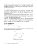
Both types of residual stress distributions are simulated experimentally in a specially
designed vibration test rig for rolling bearings (Gegner & Nierlich, 2008). A type N CRB is
used. The stationary lipless outer ring of the test bearing is displaced and experiences high
vibrational loading via the sliding contact to the rollers. It thus becomes the specimen. In
Tribological Aspects of Rolling Bearing Failures
65
addition to the radial load, controlled uni- to triaxial vibrations can be applied in axial,
tangential and radial direction. Figure 35 displays a photograph of the rig. It represents a
view of the housing of the test bearing and the equipment for the transmission of axial and
tangential vibrations (radial excitation from below) with thermocouples and displacement
sensors.
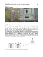
A micro friction model of the rolling-sliding contact is introduced by means of Figure 36. It
describes the effect of vibrational loading. As shown in Figure 36, tangential forces by
sliding friction acting on a rolling contact increase the equivalent stress and shift its
maximum toward the surface on indentation-free raceways (Broszeit et al., 1977). A
transition, indicated by solid-line curves, occurs between friction coefficients μ of 0.2 and
0.3: above and below μ=0.25, the increasing maximum of the Tresca equivalent stress is
located directly on or near the surface, respectively. If the yield strength of the material is
exceeded (cf. Figure 5), therefore, type A or B residual stress depth profiles are generated.
Fig. 35. Housing of the test bearing with devices for vibration generation
Material response to vibrational loading, which causes increased mixed friction, is described
in the tribological model by partitioning the nominal contact area A into microscopic
sections of different friction coefficients (Gegner & Nierlich, 2008). The inset of Figure 36
illustrates the basic idea. In some subdomains, arranged e.g. in the form of dry spots or
bands, peak values from μ
>
≈0.2 (type B) to μ
>
≥0.3 (type A) are supposed to be reached
intermittently for short periods. The thixotropy effect supports this concept because
shearing of the lubricant by vibrational loading reduces the viscosity, which increases the
tendency to mixed friction. In the other subareas of the contact, μ
<
is much lower so that the
average friction coefficient μ
(eff)
, meeting a mixing rule, remains below 0.1 as typical of
running rolling bearings. Besides the verified compressive residual stress buildup,
nonuniform cyclic mechanical loading of the contact area by, in general, complex three-
Tribology - Lubricants and Lubrication
66
dimensional vibrations is also evident from occasionally observed dent-like plastic
deformation on the surface, spots of dark etching regions in the microstructure of the
outermost material and varying preferred orientation of yielding across the raceway width,
reflected in differing tangential and axial components of the residual stresses in the affected
edge zone (Gegner & Nierlich, 2008). Friction increase is confirmed by temperature rise in
the lubricating gap that correlates with the power loss per contact area. This effect can be
exploited to easily assess the vibration resistance of specific oils or greases on the adapted
bearing test rig (Gegner & Nierlich, 2008).
Fig. 36. Distribution of the Tresca equivalent stress below a rolling-sliding contact (z
0
depth
indicated for pure radial load, i.e. μ=0) and illustration of the tribological model of localized
friction coefficient in the inset (F
n
is the normal force)
Under the influence of vibrations, disturbance of proper contact operating conditions in a
way that high shearing stresses are induced in the lubricating film can promote lubricant
degradation (Kudish & Covitch, 2010). Reduced lubricity enhances the effect of sliding
friction, e.g. described in the tribological model of Figure 36. Further to the discussed
mechanical and thermal influence, vibration loading induces chemical aging of the lubricant
and its additives (Gegner & Nierlich, 2008). Contaminations, like water or wear debris,
increase the effect. The gradual decomposition process and associated acidification of the
lubricant promote, for instance, the initiation of surface cracks on the raceway by
tribochemical dissolution of nonmetallic MnS inclusion lines, which is discussed in the next
section.
5.2 Tribochemically initiated surface cracks
First, Figure 37 gives a demonstrative example of a corrosive attack by a decomposed
lubricant. The etching pattern on the raceway reveals chemical smoothing of the surface.
Copper contamination by abrasion from the graphite-brass ground brush of the diesel
electric locomotive gets into the grease of the train wheel bearing and accelerates lubricant
aging. As evident from Figure 37, the foreign particles also cause indentations on the
raceway. An electrical oil sensor system can be used for online condition monitoring of the
lubricant (Gegner et al., 2010). The application in industrial gearboxes, for instance of wind
turbines, is of special practical interest. Note that the (e.g., extreme pressure) additives
markedly influence the electrical properties of the lubricant (Prashad, 2006).
Tribological Aspects of Rolling Bearing Failures
67
Fig. 37. SEM-SE image of a chemical surface attack on the outer ring raceway of a CRB
As exemplified by Figure 38, some manganese sulfide lines intersect the rolling contact
surface. Such inclusions are manufacturing related from the steelmaking process, despite the
high level of cleanliness of bearing grades.
Fig. 38. LOM micrograph of the etched metallographic section of a sulfide inclusion line
intersecting the surface of the inner ring raceway of a cylindrical roller bearing
On the inner ring raceway of a cylindrical roller bearing of a weaving machine examined in
Figure 39, mixed friction is indicated by the mechanically smoothed honing structure. Due
to aging of the lubricating oil, as detected under vibration loading, the gradually acidifying
fluid attacks the steel surface. Tribochemical dissolution of manufacturing related MnS
inclusion lines leaves crack-like defects on the raceway. Sulfur is continuously removed as
gaseous H
2
S by hydrogen from decomposition products of the lubricant:
MnS + H
2
→ H
2
S
↑
+ Mn (6)
The remaining manganese is then preferentially corroded out. This new mechanism of crack
formation on tribologically loaded raceway surfaces is verified by chemical characterization
using energy dispersive X-ray (EDX) microanalysis on the SEM. The EDX spectra in Figure
39, recorded at an acceleration voltage of 20 kV, confirm residues of manganese and sulfur
at four sites (S1 to S4) of an emerging crack, thus excluding accidental intersection. The ring
is made of martensitically hardened bearing steel. Reaction layer formation on the raceway
is reflected in the signals of phosphorus from lubricant additives and oxygen.
Crack initiation by tribochemical reaction is also found on lateral surfaces of rollers. In
Figure 40, remaining manganese and sulfur are detected by elemental mapping in the insets
on the right.
Tribology - Lubricants and Lubrication
68
Fig. 39. SEM-SE images of cracks on the IR raceway of a CRB from the gearbox of a weaving
machine and EDX spectra S1 to S4 taken at the indicated analysis positions
Fig. 40. SEM-SE image of a crack on a CRB roller and elemental mapping (area as indicated)
Tribological Aspects of Rolling Bearing Failures
69
The tribochemical dissolution of MnS lines on raceway surfaces during the operation of
rolling bearings also agrees with the general tendency that inclusions of all types reduce the
corrosion resistance of the steel. The chemical attack occurs by the lubricant aged in service.
The example of an early stage of defect evolution in Figure 41a points out that continuous
dissolution but not fracturing of MnS inclusions gradually initiates a surface crack. Three
analysis positions, where residues of manganese and sulfur are found, are indicated in the
SEM image. An exemplary EDX spectrum is shown in Figure 41b. The inner ring raceway of
the ball bearing from a car alternator reveals high-frequency electric current passage (cf.
Figure 26a) that promotes lubricant aging (see section 4.3).
Fig. 41. Tribochemically induced crack evolution on the IR raceway of a DGBB revealing
(a) a SEM-SE image with indicated sites where EDX analysis proves the presence of residues
of MnS dissolution and (b) a recorded EDX spectrum exemplarily of the analysis results
After defect initiation on MnS inclusions, further damage development involves shallow
micropitting (Gegner & Nierlich, 2008). Figure 42a also suggests crack propagation into the
depth. Four sites of verified MnS residues are indicated, for which Figure 42b provides a
representative detection example. The partly smoothed raceway reflects the effect of mixed
friction.
Fig. 42. Documentation of damage evolution by (a) a SEM-SE image of shallow material
removals along dissolved MnS inclusions on the IR raceway of a TRB from an industrial
gearbox with indication of four positions where EDX analysis reveals MnS residues and
(b) EDX spectrum exemplarily of the analysis results recorded at the sites given in Figure 42a
Tribology - Lubricants and Lubrication
70
The EDX reference analysis of bearing steel is provided in Figure 43. It allows comparisons
with the spectra of Figures 39, 41b and 42b.
Fig. 43. EDX reference spectrum of bearing steel for comparison of the signals
5.3 Gray staining – Corrosion rolling contact fatigue
Gray staining by dense micropitting, well known as a surface damage on tooth flanks of
gears, is also caused by mixed friction in rolling-sliding contact. The flatly expanded shallow
material fractures of only few µm depth, which cover at least parts of an affected raceway,
are frequently initiated along honing marks. In Figure 44a, propagation of material
delamination to the right occurs into sliding direction. Typical features of the influence of
corrosion are visible on the open fracture surfaces. The corresponding XRD material
response analysis in Figure 44b shows that vibrational loading of the tribological contact can
cause gray staining. Note that the shallow micropits do not affect the residual stress state
considerably. The smoothed raceway of Fig. 44a, which indicates mixed friction, is virtually
free of indentations. A characteristic type A vibration residual stress profile, maybe with
some type B contribution in 100 µm depth (cf. Figures 33 and 36, z
0
much larger), is
obtained. The XRD rolling contact fatigue damage parameter of b/B≥0.83 reaches or slightly
exceeds the L
10
equivalent value of 0.86 for the surface failure mode of roller bearings.
Fig. 44. Investigation of gray staining on the IR raceway of a CRB revealing (a) a SEM-SE
image and (b) the measured type A vibration residual stress and XRD peak width
distribution