Advances in Haptics Part 2 potx
Bạn đang xem bản rút gọn của tài liệu. Xem và tải ngay bản đầy đủ của tài liệu tại đây (4.18 MB, 40 trang )
AdvancesinHaptics32
The second device uses a planar array of cylindrical coils to levitate a platform of one or
more magnets. By using redundant control methods and an experimentally measured high
resolution model of the forces and torques generated on the levitated magnets from each
coil, the translation range of the magnet in horizontal directions and its rotation in all
directions can be extended indefinitely. These new devices permit fuller wrist and forearm
motions of the user for haptic interaction rather than the fingertips-only motions provided
by previous magnetic levitation haptic interface devices. Design, analysis, and control
methods are presented with measured haptic performance characteristics and haptic
interaction task results from both devices.
The following section surveys current technology background in magnetic levitation and
grasped haptic interaction devices actuated by motorized linkages and/or cables. Section 3
describes early Loretz force magnetic levitation devices developed for haptic interaction by
Hollis, Salcudean, and Berkelman. Sections 4 and 5 describe our current development of a
Lorentz force magnetic levitation haptic interface device with a new magnet and coil
configuration to increase its translation and rotation ranges and a levitation system using an
array of cylindrical coils to levitate one or more disk magnets, followed by a future work
and conclusion section.
2. Research Background
2.1 Magnetic Levitation Systems
Magnetic levitation systems can provide advantages for applications in manipulation (Oh et
al., 1993; Khamesee & Shameli, 2005) fine positioning (Kim & Trumper, 1998; Kim et al.,
2004), and haptic interaction (Hollis & Salcudean, 1993; Berkelman & Hollis, 2000). Surveys
of magnetic levitation technology for rail transportation are given in (Lee et al., 2006) and for
magnetic bearings in (Schweitzer et al., 1994). Other existing systems (Wang & Busch-
Vishniac, 1994; Lai et al., 2007; Robertson et al., 2005; Zhang & Menq, 2007 ) also typically
have ranges of motion which are limited however to a small fraction of the dimensions of
the levitated body in most or all directions, and to rotation angles of less than 20 degrees.
High frequency feedback control is necessary to stabilize magnetic levitation. Non-contact
position sensing for feedback control of magnetic levitation can be provided by optical
methods using LED markers and position sensing photodiodes, Hall effect magnetic sensing
(Gohin et al., 2007), or by laser interferometry which can provide submicrometer precision
position sensing.
Lorentz force levitation was initially developed for compliant assembly robotic wrists
(Hollis and Salcudean, 1993). Hollis and Salcudean pioneered the use of Lorentz force
actuation from currents in flat racetrack-shaped coils suspended between horseshoe-shaped
magnet assemblies, producing forces independent of coil positions provided that magnetic
fields are constant.
A large range of motion levitation system for small magnets using multiple permanent
magnets, pole pieces, and actuation coils to control magnetic fields is described in
(Khamesee & Shameli, 2005). A gripper has been added to this system for magnetic
levitation micromanipulation (Craig & Khamesee, 2007), however the spatial rotation of the
magnet is uncontrolled.
Spherical motors (Yan et al., 2006; Chirikjian & Stein, 1999) have been developed to control
spatial orientation of a rigid body using magnets and coils, yet these are supported by
bearings and not levitated or controlled in position. A dipole model for simplified magnetic
field torque computations in spherical motor is presented in (Lee et al., 2009).
The previous work most closely related to our current research on levitation of cylindrical
magnets using a coil array was by (Groom & Britcher, 1992), who carried out extensive
analysis of electromagnetic actuation, rigid body dynamics, and feedback control methods
for levitation with large rotations. Owing to limitations in position and orientation sensing,
implementation was limited to small motions however. Baheti and Koumboulis (Baheti,
1984; Koumboulis & Skarpetis, 1996) have also carried out related work on magnetic
suspension and balance systems for models in wind tunnels.
2.2 High-Fidelity Haptic Interface Devices
Haptic interface devices are typically actuated by DC motors through linkages and low-
friction drivetrains such as belts and cables. As the motors produce torque directly, it is
straightforward to generate haptic forces to the user given the kinematics of the linkage.
High fidelity haptic interaction with position control bandwidths greater than 100 Hz may
be realized by designing the linkage to be as stiff and lightweight as possible, with minimal
joint friction and backlash. Parallel linkage designs can be made particularly stiff and
lightweight, although joint friction may be more significant. Many of these devices provide
3 DOF force feedback only, as this is sufficent for haptic interaction at a single “fingertip”
point and a 6 DOF mechanism must add complexity, mass, and friction which reduce its
dynamic performance.
The most widely used haptic interface devices are the Phantom devices from Sensable
Technologies Inc (Massie & Salisbury, 1994). In these devices the user grasps a pen which is
mounted on a gimbal to a counterweighted, cable-driven parallelogram linkage. 3 DOF
force feedback and and 6 DOF force and torque feedback models of various sizes and
configurations are available. The Delta haptic device (Grange et al., 2001) is based on 3
parallel link sets and has similar properties, and is also commercially available in 3 and 6
DOF feedback versions.
The Pantograph (Hayward et al., 1994) design maximizes the control bandwith obtainable
from a 2 DOF planar parallelogram linkage. The Freedom 6/7 (Hayward, 1995) devices
provide 6 and 7 DOF with an attached gripper using a complex linkage with cable drives.
3. Racetrack Coil Lorentz Force Magnetic Levitation Haptic Interfaces
3.1 IBM Magic Wrist
The Magic Wrist was adapted for haptic interaction by fixing it to a stationary base rather
than a robotic arm (Berkelman et al., 1995), as shown in Figure 1. This device provided high
control bandwidths, position resolution, and stiff haptic contacts, but its motion range is
limited to less than 10 mm and 10 degrees rotation. The levitated coils in this device are
embedded in a hexagonal box.
UsingMagneticLevitationforHapticInteraction 33
The second device uses a planar array of cylindrical coils to levitate a platform of one or
more magnets. By using redundant control methods and an experimentally measured high
resolution model of the forces and torques generated on the levitated magnets from each
coil, the translation range of the magnet in horizontal directions and its rotation in all
directions can be extended indefinitely. These new devices permit fuller wrist and forearm
motions of the user for haptic interaction rather than the fingertips-only motions provided
by previous magnetic levitation haptic interface devices. Design, analysis, and control
methods are presented with measured haptic performance characteristics and haptic
interaction task results from both devices.
The following section surveys current technology background in magnetic levitation and
grasped haptic interaction devices actuated by motorized linkages and/or cables. Section 3
describes early Loretz force magnetic levitation devices developed for haptic interaction by
Hollis, Salcudean, and Berkelman. Sections 4 and 5 describe our current development of a
Lorentz force magnetic levitation haptic interface device with a new magnet and coil
configuration to increase its translation and rotation ranges and a levitation system using an
array of cylindrical coils to levitate one or more disk magnets, followed by a future work
and conclusion section.
2. Research Background
2.1 Magnetic Levitation Systems
Magnetic levitation systems can provide advantages for applications in manipulation (Oh et
al., 1993; Khamesee & Shameli, 2005) fine positioning (Kim & Trumper, 1998; Kim et al.,
2004), and haptic interaction (Hollis & Salcudean, 1993; Berkelman & Hollis, 2000). Surveys
of magnetic levitation technology for rail transportation are given in (Lee et al., 2006) and for
magnetic bearings in (Schweitzer et al., 1994). Other existing systems (Wang & Busch-
Vishniac, 1994; Lai et al., 2007; Robertson et al., 2005; Zhang & Menq, 2007 ) also typically
have ranges of motion which are limited however to a small fraction of the dimensions of
the levitated body in most or all directions, and to rotation angles of less than 20 degrees.
High frequency feedback control is necessary to stabilize magnetic levitation. Non-contact
position sensing for feedback control of magnetic levitation can be provided by optical
methods using LED markers and position sensing photodiodes, Hall effect magnetic sensing
(Gohin et al., 2007), or by laser interferometry which can provide submicrometer precision
position sensing.
Lorentz force levitation was initially developed for compliant assembly robotic wrists
(Hollis and Salcudean, 1993). Hollis and Salcudean pioneered the use of Lorentz force
actuation from currents in flat racetrack-shaped coils suspended between horseshoe-shaped
magnet assemblies, producing forces independent of coil positions provided that magnetic
fields are constant.
A large range of motion levitation system for small magnets using multiple permanent
magnets, pole pieces, and actuation coils to control magnetic fields is described in
(Khamesee & Shameli, 2005). A gripper has been added to this system for magnetic
levitation micromanipulation (Craig & Khamesee, 2007), however the spatial rotation of the
magnet is uncontrolled.
Spherical motors (Yan et al., 2006; Chirikjian & Stein, 1999) have been developed to control
spatial orientation of a rigid body using magnets and coils, yet these are supported by
bearings and not levitated or controlled in position. A dipole model for simplified magnetic
field torque computations in spherical motor is presented in (Lee et al., 2009).
The previous work most closely related to our current research on levitation of cylindrical
magnets using a coil array was by (Groom & Britcher, 1992), who carried out extensive
analysis of electromagnetic actuation, rigid body dynamics, and feedback control methods
for levitation with large rotations. Owing to limitations in position and orientation sensing,
implementation was limited to small motions however. Baheti and Koumboulis (Baheti,
1984; Koumboulis & Skarpetis, 1996) have also carried out related work on magnetic
suspension and balance systems for models in wind tunnels.
2.2 High-Fidelity Haptic Interface Devices
Haptic interface devices are typically actuated by DC motors through linkages and low-
friction drivetrains such as belts and cables. As the motors produce torque directly, it is
straightforward to generate haptic forces to the user given the kinematics of the linkage.
High fidelity haptic interaction with position control bandwidths greater than 100 Hz may
be realized by designing the linkage to be as stiff and lightweight as possible, with minimal
joint friction and backlash. Parallel linkage designs can be made particularly stiff and
lightweight, although joint friction may be more significant. Many of these devices provide
3 DOF force feedback only, as this is sufficent for haptic interaction at a single “fingertip”
point and a 6 DOF mechanism must add complexity, mass, and friction which reduce its
dynamic performance.
The most widely used haptic interface devices are the Phantom devices from Sensable
Technologies Inc (Massie & Salisbury, 1994). In these devices the user grasps a pen which is
mounted on a gimbal to a counterweighted, cable-driven parallelogram linkage. 3 DOF
force feedback and and 6 DOF force and torque feedback models of various sizes and
configurations are available. The Delta haptic device (Grange et al., 2001) is based on 3
parallel link sets and has similar properties, and is also commercially available in 3 and 6
DOF feedback versions.
The Pantograph (Hayward et al., 1994) design maximizes the control bandwith obtainable
from a 2 DOF planar parallelogram linkage. The Freedom 6/7 (Hayward, 1995) devices
provide 6 and 7 DOF with an attached gripper using a complex linkage with cable drives.
3. Racetrack Coil Lorentz Force Magnetic Levitation Haptic Interfaces
3.1 IBM Magic Wrist
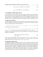
The Magic Wrist was adapted for haptic interaction by fixing it to a stationary base rather
than a robotic arm (Berkelman et al., 1995), as shown in Figure 1. This device provided high
control bandwidths, position resolution, and stiff haptic contacts, but its motion range is
limited to less than 10 mm and 10 degrees rotation. The levitated coils in this device are
embedded in a hexagonal box.
AdvancesinHaptics34
Fig. 1. IBM Magic Wrist used as haptic interface device
3.2 UBC Teleoperation Master and Powermouse
The Teloperation Master developed at the University of British Columbia (Salcudean et al.,
1995) has a similar size and motion range as the Magic Wrist, yet has a novel magnet and
coil configuration. Its structure, with the grasped cover removed, is shown in Figure 2(a).
The Powermouse (Salcudean & Parker, 1997) is a smaller desktop device, with reduced mass
and a small motion range adaped for fingertip interaction. Its levitation coils are arranged
on the faces of a cube embedded inside the housing of the device shown in Figure 2(b).
3.3 CMU / Butterfly Haptics Maglev Haptic Interface
Another Lorentz force magnetic levitation haptic interface device was developed at
Carnegie Mellon by Berkelman and Hollis (Berkelman & Hollis, 2000) , with the coil and
magnet configuration and position sensing system modified to provide a large increase in
the ranges of motion in both translation, at 25 mm, and rotation at 15 degrees. The main
factor in the motion range increase was to embed large actuator coils tightly together in a
thin hemispherical shell, with the interaction handle mounted at the center. The top of the
device and its use with a graphically displayed environment on a PC are shown in Figure 3.
Fig. 2. (a) UBC Teleoperation Master, (b) UBC Powermouse
Fig. 3. Carnegie Mellon University Prototype (a) Levitated Handle Grasped by User, (b)
Interaction with Simulated Environment
A commercial successor to this design, with improved position sensing feedback, a lighter,
stiffer levitated hemisphere shell, and with a software programming interface, is currently
produced by Butterfly Haptics LLC. At least 10 devices are in use in several different
research labs composing a maglev haptic consortium.
4. Double Coil Layer Lorentz Magnetic Levitation Design
4.1 Design
Our first extended range magnetic levitation design is a Lorentz levitation device with coils
on a spherical shell and a user handle mounted at the center of the shell, as in the Carnegie
Mellon Lorentz devices. This device uses a novel coil shape, magnet configuration, and
arranges the coils in two layers so that the magnetic field gap widths can be doubled at
approximately the same field intensity as before and the coil areas can be increased many
times more on a shell of approximately the same radius, resulting in a doubling of the
translation range and a tripling of the rotation range in all directions. The basic design is
described in more detail in (Berkelman, 2007) and shown in Figure 4. Instead of using
racetrack-shaped coils in which the coil windings follow oval paths, a new coil shape shown
in Figure 5(a) is used in which the windings follow straight paths across the centers of the
coils, and curved return paths around the periphery of the round coils. This allows the coils
to be arranged in two layers as in Figure 5(b), with the straight wires across the centers of
the coils orthogonal to one another. In this arrangement, the areas of the coils can be
increased considerably without increasing the radius of the spherical shell, and each pair of
layered coils requires only two magnets to generate their shared magnetic field. Large,
curved iron pole pieces pass above and around the levitated coil assemblies to form a
magnetic flux path from one magnet to the other on the opposite sides of each gap. The
centers of the coil pairs are arranged at 0, 120, and 240 degrees around the circumference at
an angle of 35 degrees below the horizontal plane, on a spherical surface with a 125 mm
radius, and each coil spans a solid angle of 90 degrees. The effective solid angle of each coil
is reduced to approximately 70 degrees due to the width of the magnets and the return
UsingMagneticLevitationforHapticInteraction 35
Fig. 1. IBM Magic Wrist used as haptic interface device
3.2 UBC Teleoperation Master and Powermouse
The Teloperation Master developed at the University of British Columbia (Salcudean et al.,
1995) has a similar size and motion range as the Magic Wrist, yet has a novel magnet and
coil configuration. Its structure, with the grasped cover removed, is shown in Figure 2(a).
The Powermouse (Salcudean & Parker, 1997) is a smaller desktop device, with reduced mass
and a small motion range adaped for fingertip interaction. Its levitation coils are arranged
on the faces of a cube embedded inside the housing of the device shown in Figure 2(b).
3.3 CMU / Butterfly Haptics Maglev Haptic Interface
Another Lorentz force magnetic levitation haptic interface device was developed at
Carnegie Mellon by Berkelman and Hollis (Berkelman & Hollis, 2000) , with the coil and
magnet configuration and position sensing system modified to provide a large increase in
the ranges of motion in both translation, at 25 mm, and rotation at 15 degrees. The main
factor in the motion range increase was to embed large actuator coils tightly together in a
thin hemispherical shell, with the interaction handle mounted at the center. The top of the
device and its use with a graphically displayed environment on a PC are shown in Figure 3.
Fig. 2. (a) UBC Teleoperation Master, (b) UBC Powermouse
Fig. 3. Carnegie Mellon University Prototype (a) Levitated Handle Grasped by User, (b)
Interaction with Simulated Environment
A commercial successor to this design, with improved position sensing feedback, a lighter,
stiffer levitated hemisphere shell, and with a software programming interface, is currently
produced by Butterfly Haptics LLC. At least 10 devices are in use in several different
research labs composing a maglev haptic consortium.
4. Double Coil Layer Lorentz Magnetic Levitation Design
4.1 Design
Our first extended range magnetic levitation design is a Lorentz levitation device with coils
on a spherical shell and a user handle mounted at the center of the shell, as in the Carnegie
Mellon Lorentz devices. This device uses a novel coil shape, magnet configuration, and
arranges the coils in two layers so that the magnetic field gap widths can be doubled at
approximately the same field intensity as before and the coil areas can be increased many
times more on a shell of approximately the same radius, resulting in a doubling of the
translation range and a tripling of the rotation range in all directions. The basic design is
described in more detail in (Berkelman, 2007) and shown in Figure 4. Instead of using
racetrack-shaped coils in which the coil windings follow oval paths, a new coil shape shown
in Figure 5(a) is used in which the windings follow straight paths across the centers of the
coils, and curved return paths around the periphery of the round coils. This allows the coils
to be arranged in two layers as in Figure 5(b), with the straight wires across the centers of
the coils orthogonal to one another. In this arrangement, the areas of the coils can be
increased considerably without increasing the radius of the spherical shell, and each pair of
layered coils requires only two magnets to generate their shared magnetic field. Large,
curved iron pole pieces pass above and around the levitated coil assemblies to form a
magnetic flux path from one magnet to the other on the opposite sides of each gap. The
centers of the coil pairs are arranged at 0, 120, and 240 degrees around the circumference at
an angle of 35 degrees below the horizontal plane, on a spherical surface with a 125 mm
radius, and each coil spans a solid angle of 90 degrees. The effective solid angle of each coil
is reduced to approximately 70 degrees due to the width of the magnets and the return
AdvancesinHaptics36
paths of the wires around the edges of the coils and the magnet gaps are 53 mm, so that the
device can provide a motion range of 50 mm in translation and approximately 60 degrees in
rotation in all directions.
As the translation range is approximately double and the rotation range is triple that of
previous levitated haptic interaction devices, the workspace volume is actually increased by
a factor of 8 and the rotation space by a factor of 27. The increased motion range
Fig. 4. Extended motion range spherical shell Lorentz force magnetic levitation device (a)
Design, (b) device as fabricated
Fig. 5. (a) Double layer circular coil wire paths, (b) Magnet and double coil configuration
of the new device is not merely an incremental improvement, but enables a qualitatively
much greater variety of interactive tasks to be simulated as the increased range is
comparable to the full range of human wrist movement, whereas previous haptic levitation
devices could accommodate fingertip motions only. For example, common manual
manipulation tasks such as turning doorknobs, keys, and hexagonal nuts and screwheads
can be realistically haptically simulated with the new device, and 60 degrees of rotation and
50 mm of translation is sufficient to simulate many tasks in minimally invasive surgery
(Rosen et al., 2002).
The force generated by each coil can be modelled as a single force vector at the center of
each coil, and one coil in each pair generates vertical and the other generates horizontal
forces. The magnitude of the force generated by each coil is approximately 3.0
Newtons/Amp. With the coil center locations at:
1,2 3,4 5,6
cos(35) cos(120) cos(35) cos(240) cos(35)
0.125 0 , 0.125 sin(120) sin(35) , 0.125 sin(240) cos(35)
sin(35) sin (35) sin (35)
r r r
(1)
in m, and the forces generated by each coil at:
1 1 2 2 3 3
sin(35) 0 cos(120) sin(35)
3.0 0 , 3.0 1 , 3.0 sin(120) sin(35) ,
cos(35) 0 cos(35)
f
i f i f i
(2)
4 4 5 5 6 6
sin(20) cos(240) sin(35) sin(240)
3.0 cos(35) , 3.0 sin(240) sin(35) , 3.0 cos(240) ,
0 cos(35) 0
f
i f i f i
in Newtons, with angles in degrees, then the current to force and torque vector
transformation matrix can be given as:
1
2
3
1 2
41 1 2 2
5
6
x
y
z
x
y
z
f
i
f
i
i
f f f
ir f r f
i
i
(3)
to relate currents in A to forces in N and torques in N-m. When the sphere radius and the
force magnitudes are normalized to 1 to compensate for differences in force and torque
units, the condition number of the transformation matrix is 3.7, indicating that the matrix is
invertable and forces and torques can be efficiently generated in all directions without
requiring excessively larger coil currents for some directions.
4.2 Analysis and Fabrication
Electromagnetic finite element analysis
was performed to find magnet shapes and
dimensions to concentrate and maximize magnetic fields necessary for levitation. This
analysis indicated that the minimum field strength in between magnets is approximately
0.25 T, which is expected from experience (Berkelman & Hollis, 2000) to be sufficient for
levitation and high-fidelity haptic interaction. The mass of the fabricated levitated body is
1200 g; by fabricating new coils using aluminum wire and using a more lightweight
UsingMagneticLevitationforHapticInteraction 37
paths of the wires around the edges of the coils and the magnet gaps are 53 mm, so that the
device can provide a motion range of 50 mm in translation and approximately 60 degrees in
rotation in all directions.
As the translation range is approximately double and the rotation range is triple that of
previous levitated haptic interaction devices, the workspace volume is actually increased by
a factor of 8 and the rotation space by a factor of 27. The increased motion range
Fig. 4. Extended motion range spherical shell Lorentz force magnetic levitation device (a)
Design, (b) device as fabricated
Fig. 5. (a) Double layer circular coil wire paths, (b) Magnet and double coil configuration
of the new device is not merely an incremental improvement, but enables a qualitatively
much greater variety of interactive tasks to be simulated as the increased range is
comparable to the full range of human wrist movement, whereas previous haptic levitation
devices could accommodate fingertip motions only. For example, common manual
manipulation tasks such as turning doorknobs, keys, and hexagonal nuts and screwheads
can be realistically haptically simulated with the new device, and 60 degrees of rotation and
50 mm of translation is sufficient to simulate many tasks in minimally invasive surgery
(Rosen et al., 2002).
The force generated by each coil can be modelled as a single force vector at the center of
each coil, and one coil in each pair generates vertical and the other generates horizontal
forces. The magnitude of the force generated by each coil is approximately 3.0
Newtons/Amp. With the coil center locations at:
1,2 3,4 5,6
cos(35) cos(120) cos(35) cos(240) cos(35)
0.125 0 , 0.125 sin(120) sin(35) , 0.125 sin(240) cos(35)
sin(35) sin (35) sin (35)
r r r
(1)
in m, and the forces generated by each coil at:
1 1 2 2 3 3
sin(35) 0 cos(120) sin(35)
3.0 0 , 3.0 1 , 3.0 sin(120) sin(35) ,
cos(35) 0 cos(35)
f
i f i f i
(2)
4 4 5 5 6 6
sin(20) cos(240) sin(35) sin(240)
3.0 cos(35) , 3.0 sin(240) sin(35) , 3.0 cos(240) ,
0 cos(35) 0
f
i f i f i
in Newtons, with angles in degrees, then the current to force and torque vector
transformation matrix can be given as:
1
2
3
1 2
41 1 2 2
5
6
x
y
z
x
y
z
f
i
f
i
i
f f f
ir f r f
i
i
(3)
to relate currents in A to forces in N and torques in N-m. When the sphere radius and the
force magnitudes are normalized to 1 to compensate for differences in force and torque
units, the condition number of the transformation matrix is 3.7, indicating that the matrix is
invertable and forces and torques can be efficiently generated in all directions without
requiring excessively larger coil currents for some directions.
4.2 Analysis and Fabrication
Electromagnetic finite element analysis
was performed to find magnet shapes and
dimensions to concentrate and maximize magnetic fields necessary for levitation. This
analysis indicated that the minimum field strength in between magnets is approximately
0.25 T, which is expected from experience (Berkelman & Hollis, 2000) to be sufficient for
levitation and high-fidelity haptic interaction. The mass of the fabricated levitated body is
1200 g; by fabricating new coils using aluminum wire and using a more lightweight
AdvancesinHaptics38
support structure we aim to reduce the levitated mass to 500 g or less. In Figure 4(b), the
iron pole pieces on two of the magnet assemblies have been rotated about the magnet axes
by approximately 30 degrees to provide more ergonomic access for the user to more easily
grasp the levitated handle without affecting the magnetic fields or the range of motion of the
device.
4.3 Experimental Results
A sample large scale vertical step input motion trajectory for the free-floating levitated coils
in the vertical direction is shown in Figure 5. The control gains used were as follows:
translation rotation
Kp
2.0 N/mm 0.0875 N-m/degree
Kd
0.01 N-sec/mm 0.00035 N-m-sec/degree
As these are very preliminary results, it is expected that more careful modeling, calibration,
and signal processing will result in considerable increases of the maximum stable gains and
a more damped response.
Regarding the positioning accuracy of the levitated bowl and the stiffness of the coil
structure, it is notable that any flexion of the coils from high actuation forces would not
affect the position accuracy of the manipulation handle, as the position sensing feedback is
from LED markers close to the center of the structure, which is reinforced with an additional
layer of aluminum and a collar around the base of the handle. Furthermore, for haptic
interaction applications, absolute position accuracy of the device is not as critical as the
incremental position and force accuracy and control bandwidths to the perceived fidelity of
the haptic interaction.
Fig. 6. Vertical step response results for new Lorentz levitation device
5. Magnet Levitation by Planar Array of Cylindrical Coils
5.1 Design
A redundant actuation method was used to levitate a single magnet by combining actuation
forces and torques from more than 5 coils at a time. The potential advantages of redundant
actuation compared to selections of coil subsets at each magnet position are that the
maximum required coil currents for levitation may be reduced by distributing the
generation of lifting forces over more coils, and discontinuous force disturbances due to
measurement and position errors as coil currents are abruptly switched on and off during
motion trajectories can be avoided. Sixteen coils of 25 mm diameter, 30 mm height, and 1000
windings are currently used, providing a motion range of approximately 100x80x30 mm
with potentially unlimited tilt range. Rotation about the axis of a single disk magnet cannot
be controlled due to its radial symmetry, so single magnet platform levitation leaves this
yaw angle uncontrolled. The array levitation control methods, design, and initial results are
described in further detail in (Berkelman & Dzadovsky, 2008). The levitated mass is
approximately 125 g.
5.2 Control
To determine the model of force and torque generation between a single magnet and coil, an
experimental setup of motion stages and a force sensor was used as in Figure 7(a). Although
it is possible to obtain a force and torque generation model either analytically (as described
in [5]) or from electromagnetic finite element analysis, in this case it is simpler and faster to
obtain the model experimentally, and furthermore the effects of variations in the magnet
material and its magnetization are accounted for directly.
The 6 force and torque elements generated between the magnet and coil were recorded at 1
mm intervals of vertical and radial separation and 30 degree angular intervals, resulting in
the force and torque data partially shown in shown in Figure 7(b). The forces and torques
generated by each coil were found to be independent and proportional to each coil current
to a very close approximation, allowing the current to force and torque transformation to be
represented in linear matrix form at any magnet position and orientation. This data was
used to calculate the current to force and torque transformation for single magnet levitation.
Defining the angle from each coil center i to the magnet center in the horizontal plane as
i
,
the transformation from currents to forces and torques is as follows:
1 1 1 1
1 1 1 1
1
1
cos( ) ( , , , ) sin( ) ( , , , )
sin( ) ( , , , ) cos( ) ( , , , )
( , , , )
cos( )
x i y i
x
x i y iy
x iz
x
y
z
f r z f r z
f
f r z f r z
f
f r zf
f
1
2
1 1 1
1 1 1 1
1
( , , , ) sin( ) ( , , , )
sin( ) ( , , , ) cos( ) ( , , , )
( , , , )
x i y i
x i y i
x i
i
i
r z f r z
f r z f r z
f r z
(4)
where z is the levitation height of the magnet center above the coil plane, and r
i
is the
horizontal distance from the center of the coil i to the center of the magnet. Since the coil
forces
UsingMagneticLevitationforHapticInteraction 39
support structure we aim to reduce the levitated mass to 500 g or less. In Figure 4(b), the
iron pole pieces on two of the magnet assemblies have been rotated about the magnet axes
by approximately 30 degrees to provide more ergonomic access for the user to more easily
grasp the levitated handle without affecting the magnetic fields or the range of motion of the
device.
4.3 Experimental Results
A sample large scale vertical step input motion trajectory for the free-floating levitated coils
in the vertical direction is shown in Figure 5. The control gains used were as follows:
translation rotation
K
p
2.0 N/mm 0.0875 N-m/degree
K
d
0.01 N-sec/mm 0.00035 N-m-sec/degree
As these are very preliminary results, it is expected that more careful modeling, calibration,
and signal processing will result in considerable increases of the maximum stable gains and
a more damped response.
Regarding the positioning accuracy of the levitated bowl and the stiffness of the coil
structure, it is notable that any flexion of the coils from high actuation forces would not
affect the position accuracy of the manipulation handle, as the position sensing feedback is
from LED markers close to the center of the structure, which is reinforced with an additional
layer of aluminum and a collar around the base of the handle. Furthermore, for haptic
interaction applications, absolute position accuracy of the device is not as critical as the
incremental position and force accuracy and control bandwidths to the perceived fidelity of
the haptic interaction.
Fig. 6. Vertical step response results for new Lorentz levitation device
5. Magnet Levitation by Planar Array of Cylindrical Coils
5.1 Design
A redundant actuation method was used to levitate a single magnet by combining actuation
forces and torques from more than 5 coils at a time. The potential advantages of redundant
actuation compared to selections of coil subsets at each magnet position are that the
maximum required coil currents for levitation may be reduced by distributing the
generation of lifting forces over more coils, and discontinuous force disturbances due to
measurement and position errors as coil currents are abruptly switched on and off during
motion trajectories can be avoided. Sixteen coils of 25 mm diameter, 30 mm height, and 1000
windings are currently used, providing a motion range of approximately 100x80x30 mm
with potentially unlimited tilt range. Rotation about the axis of a single disk magnet cannot
be controlled due to its radial symmetry, so single magnet platform levitation leaves this
yaw angle uncontrolled. The array levitation control methods, design, and initial results are
described in further detail in (Berkelman & Dzadovsky, 2008). The levitated mass is
approximately 125 g.
5.2 Control
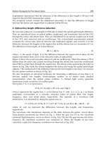
To determine the model of force and torque generation between a single magnet and coil, an
experimental setup of motion stages and a force sensor was used as in Figure 7(a). Although
it is possible to obtain a force and torque generation model either analytically (as described
in [5]) or from electromagnetic finite element analysis, in this case it is simpler and faster to
obtain the model experimentally, and furthermore the effects of variations in the magnet
material and its magnetization are accounted for directly.
The 6 force and torque elements generated between the magnet and coil were recorded at 1
mm intervals of vertical and radial separation and 30 degree angular intervals, resulting in
the force and torque data partially shown in shown in Figure 7(b). The forces and torques
generated by each coil were found to be independent and proportional to each coil current
to a very close approximation, allowing the current to force and torque transformation to be
represented in linear matrix form at any magnet position and orientation. This data was
used to calculate the current to force and torque transformation for single magnet levitation.
Defining the angle from each coil center i to the magnet center in the horizontal plane as
i
,
the transformation from currents to forces and torques is as follows:
1 1 1 1
1 1 1 1
1
1
cos( ) ( , , , ) sin( ) ( , , , )
sin( ) ( , , , ) cos( ) ( , , , )
( , , , )
cos( )
x i y i
x
x i y iy
x iz
x
y
z
f r z f r z
f
f r z f r z
f
f r zf
f
1
2
1 1 1
1 1 1 1
1
( , , , ) sin( ) ( , , , )
sin( ) ( , , , ) cos( ) ( , , , )
( , , , )
x i y i
x i y i
x i
i
i
r z f r z
f r z f r z
f r z
(4)
where z is the levitation height of the magnet center above the coil plane, and r
i
is the
horizontal distance from the center of the coil i to the center of the magnet. Since the coil
forces
AdvancesinHaptics40
Fig. 7. (a) Motion stage and force/torque measurement setup, (b) Radial force, vertical
force, and torque generated on magnet by coil with 1.0 Ampere current
and torques are measured at discrete values of
, cubic interpolation is used to estimate the
values of the continuous functions.
For 6 degree of freedom controlled levitation of platforms with multiple disk magnets,
additional terms must be added due to the r×f torques from magnet forces f generated at a
distance r from the center of mass of the levitated platform; it is these transformation terms
which enable generation of
z
torques to control the yaw angle.
As forces and torques are both produced in 3 dimensions, and there are 16 coils in the
current setup, each resulting transformation matrix is 6x16 elements. This rectangular
matrix is kinematically redundant, as the number of actuators is greater than the DOF to be
controlled. For redundant systems in general, the Moore-Penrose pseudoinverse A
+
of A
(Moore, 1920; Penrose, 1955) can be used to calculate actuation currents I = A
+
F with the
lowest sum of squared currents for levitation control, adapting control methods developed
for redundant actuation velocity control and execution of subspace tasks as described in
(Nenchev, 1992; Baillieul, 1987). In our system however, the pseudoinverse of the
transformation matrix cannot be directly inverted to produce the coil currents to produce a
desired set of forces and torques, as no combination of coil currents can produce any torque
on the magnet about its principal axis. For 5 DOF levitation control at arbitrary orientations,
the torque vectors in the transformation matrices can rotated so that one of the torque
directions is aligned with the magnet axis, and the row corresponding to these torques is
reduced to approximately zero. This row can then be eliminated from the transformation
matrix, and the pseudoinverse of the resulting reduced 5x16 transform matrix can then be
used to calculate coil currents to generate two torques perpendicular to the axis of the
magnet to control its orientation while leaving the rotation of the magnet about its principal
axis uncontrolled.
The force/torque to current transforms are precalculated to the closest 1.0 mm in translation
and 30 degrees in orientation, and stored in a lookup table for use during realtime control.
Linear interpolation of the measured force and torque data described previously is used
online for control, as the distance and angle from each coil to the magnet are not restricted to
1 mm and 30 degree intervals. Numerical computation software was used for the calculation
of the force/torque to current transformation lookup tables.
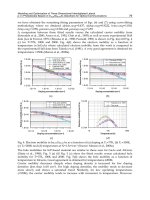
Condition numbers of the transformation matrix across the motion plane are shown for a
horizontal magnet orientation in Figure 8(a) and a vertical orientation in Figure 8(b) at a 25
mm levitation height. The locations of the 16 coil centers are indicated by asterisks ’*’, these
are arranged in a hexagonal configuration with a spacing of 35 mm. The transformation
condition numbers are greatest directly above the coil centers because the horizontal force
and torque torque generation capabilites of the coil underneath are zero although the
vertical force generation efficiencies are maximized at these locations.
Fig. 8. Coil current to force/torque vector transformation matrix condition numbers, (a)
Horizontal orientation, (b) vertical orientation
5.3 Results and Discussion
Using the system and methods described, we have realized stable levitation with 5 DOF
control of a single disk magnet, as shown in Figure 9(a), and 6 DOF control of a magnet pair
shown in Figure 9(b). A single levitated magnet may be embedded in a computer mouse
shell for user interaction, as shown in Figure 10(a), and a single magnet may be levitated in
any orientation by fixing 12 position markers to the levitated body oriented on the faces of a
dodecahedron, so that at least 3 markers are visible to the position sensor at all times, as
shown in Figure 10(b).
UsingMagneticLevitationforHapticInteraction 41
Fig. 7. (a) Motion stage and force/torque measurement setup, (b) Radial force, vertical
force, and torque generated on magnet by coil with 1.0 Ampere current
and torques are measured at discrete values of
, cubic interpolation is used to estimate the
values of the continuous functions.
For 6 degree of freedom controlled levitation of platforms with multiple disk magnets,
additional terms must be added due to the r×f torques from magnet forces f generated at a
distance r from the center of mass of the levitated platform; it is these transformation terms
which enable generation of
z
torques to control the yaw angle.
As forces and torques are both produced in 3 dimensions, and there are 16 coils in the
current setup, each resulting transformation matrix is 6x16 elements. This rectangular
matrix is kinematically redundant, as the number of actuators is greater than the DOF to be
controlled. For redundant systems in general, the Moore-Penrose pseudoinverse A
+
of A
(Moore, 1920; Penrose, 1955) can be used to calculate actuation currents I = A
+
F with the
lowest sum of squared currents for levitation control, adapting control methods developed
for redundant actuation velocity control and execution of subspace tasks as described in
(Nenchev, 1992; Baillieul, 1987). In our system however, the pseudoinverse of the
transformation matrix cannot be directly inverted to produce the coil currents to produce a
desired set of forces and torques, as no combination of coil currents can produce any torque
on the magnet about its principal axis. For 5 DOF levitation control at arbitrary orientations,
the torque vectors in the transformation matrices can rotated so that one of the torque
directions is aligned with the magnet axis, and the row corresponding to these torques is
reduced to approximately zero. This row can then be eliminated from the transformation
matrix, and the pseudoinverse of the resulting reduced 5x16 transform matrix can then be
used to calculate coil currents to generate two torques perpendicular to the axis of the
magnet to control its orientation while leaving the rotation of the magnet about its principal
axis uncontrolled.
The force/torque to current transforms are precalculated to the closest 1.0 mm in translation
and 30 degrees in orientation, and stored in a lookup table for use during realtime control.
Linear interpolation of the measured force and torque data described previously is used
online for control, as the distance and angle from each coil to the magnet are not restricted to
1 mm and 30 degree intervals. Numerical computation software was used for the calculation
of the force/torque to current transformation lookup tables.
Condition numbers of the transformation matrix across the motion plane are shown for a
horizontal magnet orientation in Figure 8(a) and a vertical orientation in Figure 8(b) at a 25
mm levitation height. The locations of the 16 coil centers are indicated by asterisks ’*’, these
are arranged in a hexagonal configuration with a spacing of 35 mm. The transformation
condition numbers are greatest directly above the coil centers because the horizontal force
and torque torque generation capabilites of the coil underneath are zero although the
vertical force generation efficiencies are maximized at these locations.
Fig. 8. Coil current to force/torque vector transformation matrix condition numbers, (a)
Horizontal orientation, (b) vertical orientation
5.3 Results and Discussion
Using the system and methods described, we have realized stable levitation with 5 DOF
control of a single disk magnet, as shown in Figure 9(a), and 6 DOF control of a magnet pair
shown in Figure 9(b). A single levitated magnet may be embedded in a computer mouse
shell for user interaction, as shown in Figure 10(a), and a single magnet may be levitated in
any orientation by fixing 12 position markers to the levitated body oriented on the faces of a
dodecahedron, so that at least 3 markers are visible to the position sensor at all times, as
shown in Figure 10(b).
AdvancesinHaptics42
Fig. 9. (a) 5 DOF motion control with single disk magnet, (b) 6 DOF motion control
Large scale motion trajectories from a single free-floating levitated magnet are shown in
Figure 11. The control gains used were as follows:
translation rotation
Kp
0.2 N/mm 5.25 N-mm/degree
Kd
0.002 N-sec/mm 0.0525 N-mm-sec/degree
The position control bandwidths of the system are limited by the maximum stable
proportional gain, or stiffness of the controller, this gain is limited in turn by the resolution
and noise level of the position sensor and the update rate of the controller. Initial levitation
of two magnet platforms has also been demonstrated for 6 degree-of-freedom levitation
control including yaw rotations.
6. Future Work and Conclusions
The planar array levitation system has greater potential for further expansion of its motion
range in horizontal directions and rotations in all directions, but it is less efficient than the
Lorentz levitation device, which can generate higher forces and torques without
overheating. Each of the two systems will be interfaced to publically available haptic
interaction software such as Chai3d and H3D to evaluate user perception and task
performance using the devices.
Further development to be undertaken for each system includes modeling of the magnetic
field variations in the Lorentz force device for better control performance, and modeling of
magnetic actuation at any rotation angle for the planar system. Coils with iron cores will be
used for more efficient actuation.
The two described magnetic levitation systems each provide greater motion ranges than any
other previous magnetic levitation device for haptic interaction. The magnetic levitation
systems and methods described are part of a larger research effort to investigate and
develop magnetic levitation for high-fidelity haptic interaction.
Fig. 10. (a) Levitated mouse with embedded magnet for haptic interaction, (b) 12 marker
levitated body for levitation at any orientation
Fig. 11. (a) Motion trajectory for magnet in horizontal orientation, (b) vertical orientation
7. References
R. Baheti, “Multivariable frequency domain controller for magnetic suspension and balance
systems,” IEEE Transactions on Automatic Control, vol. 29, no. 8, pp. 725–728, 1984.
J. Baillieul, “A constraint oriented approach to inverse problems for kinematically
redundant manipulators,” IEEE International Conference on Robotics and Automation,
Raleigh, March 1987, pp. 1827–1833.
P. J. Berkelman, R. L. Hollis, and S. E. Salculdean, "Interacting with Virtual Environments
using a Magnetic Levitation Haptic Interface", Int'l Conf. on Intelligent Robots and
Systems, Pittsburgh, August 1995.
P. J. Berkelman and R. L. Hollis, "Lorentz magnetic levitation for haptic interaction: Device
design, function, and integration with simulated environments", International
Journal of Robotics Research, 9(7):644–667, 2000.
P. J. Berkelman, "A novel coil configuration to extend the motion range of lorentz force
magnetic levitation devices for haptic interaction", IEEE/RSJ International Conference
on Intelligent Robots and Systems, San Diego, October 2007.
UsingMagneticLevitationforHapticInteraction 43
Fig. 9. (a) 5 DOF motion control with single disk magnet, (b) 6 DOF motion control
Large scale motion trajectories from a single free-floating levitated magnet are shown in
Figure 11. The control gains used were as follows:
translation rotation
Kp
0.2 N/mm 5.25 N-mm/degree
Kd
0.002 N-sec/mm 0.0525 N-mm-sec/degree
The position control bandwidths of the system are limited by the maximum stable
proportional gain, or stiffness of the controller, this gain is limited in turn by the resolution
and noise level of the position sensor and the update rate of the controller. Initial levitation
of two magnet platforms has also been demonstrated for 6 degree-of-freedom levitation
control including yaw rotations.
6. Future Work and Conclusions
The planar array levitation system has greater potential for further expansion of its motion
range in horizontal directions and rotations in all directions, but it is less efficient than the
Lorentz levitation device, which can generate higher forces and torques without
overheating. Each of the two systems will be interfaced to publically available haptic
interaction software such as Chai3d and H3D to evaluate user perception and task
performance using the devices.
Further development to be undertaken for each system includes modeling of the magnetic
field variations in the Lorentz force device for better control performance, and modeling of
magnetic actuation at any rotation angle for the planar system. Coils with iron cores will be
used for more efficient actuation.
The two described magnetic levitation systems each provide greater motion ranges than any
other previous magnetic levitation device for haptic interaction. The magnetic levitation
systems and methods described are part of a larger research effort to investigate and
develop magnetic levitation for high-fidelity haptic interaction.
Fig. 10. (a) Levitated mouse with embedded magnet for haptic interaction, (b) 12 marker
levitated body for levitation at any orientation
Fig. 11. (a) Motion trajectory for magnet in horizontal orientation, (b) vertical orientation
7. References
R. Baheti, “Multivariable frequency domain controller for magnetic suspension and balance
systems,” IEEE Transactions on Automatic Control, vol. 29, no. 8, pp. 725–728, 1984.
J. Baillieul, “A constraint oriented approach to inverse problems for kinematically
redundant manipulators,” IEEE International Conference on Robotics and Automation,
Raleigh, March 1987, pp. 1827–1833.
P. J. Berkelman, R. L. Hollis, and S. E. Salculdean, "Interacting with Virtual Environments
using a Magnetic Levitation Haptic Interface", Int'l Conf. on Intelligent Robots and
Systems, Pittsburgh, August 1995.
P. J. Berkelman and R. L. Hollis, "Lorentz magnetic levitation for haptic interaction: Device
design, function, and integration with simulated environments", International
Journal of Robotics Research, 9(7):644–667, 2000.
P. J. Berkelman, "A novel coil configuration to extend the motion range of lorentz force
magnetic levitation devices for haptic interaction", IEEE/RSJ International Conference
on Intelligent Robots and Systems, San Diego, October 2007.
AdvancesinHaptics44
P. J. Berkelman and M. Dzadovsky, "Magnet levitation and trajectory following motion
control using a planar array of cylindrical coils", ASME Dynamic Systems and Control
Conference, Ann Arbor, October 2008.
G. S. Chirikjian and D. Stein, "Kinematic design and commutation of a spherical stepper
motor", IEEE/ASME Transactions on Mechatronics, 4(4):342–353, December 1999.
D. G. Craig and M. B. Khamesee, “Motion control of a large gap magnetic suspension
system for microrobotic manipulation,” Journal of Physics D: Applied Physics, vol. 40,
no. 11, pp. 3277–3285, 2007.
S. Grange and F. Conti, P. Rouiller, P. Helmer, and C. Baur, "Overview of the Delta Haptic
Device", Eurohaptics, Birmingham UK, 2001.
A. Gohin, J. Simeray, W. X. Bing, and L. L. Qing, “Levitation device,” U. S. Patent No.
20,070,170,798, July 2007.
N. J. Groom and C. P. Britcher, "A description of a laboratory model magnetic suspension
test fixture with large angular capability", IEEE Conference on Control Applications,,
Dayton, September 1992, pp 454–459.
V. Hayward, J. Choksi, G. Lanvin, and C. Ramstein, "Design and multi-objective
optimization of a linkage for a haptic interface", ARK'94, 4th Int'l Workshop on
Advances in Robot Kinematics, Ljubliana, June 1994.
V. Hayward, "Toward a Seven Axis Haptic Device", Int'l Conf. on Intelligent Robots and
Systems, Pittsburgh, August 1995, pp. 113-139.
R. L. Hollis, S. Salcudean, and A. P. Allan, "A six degree-of-freedom magnetically levitated
variable compliance fine motion wrist: design, modeling, and control", IEEE
Transactions on Robotics and Automation, 7(3):320–332, June 1991.
R. L. Hollis and S. E. Salcudean, "Lorentz levitation technology: a new approach to fine
motion robotics, teleoperation, haptic interfaces, and vibration isolation", Proc. 6th
Int’l Symposium on Robotics Research, Hidden Valley, PA, October 1993.
W J. Kim and D. Trumper, “High-precision magnetic levitation stage for
photolithography,” Precision Engineering, vol. 22, pp. 66–77, 1998.
W J. Kim, N. Bhat, and T. Hu, “Integrated multidimensional positioner for precision
manufacturing,” Proceedings of the Institution of Mechanical Engineers Part B: Journal
of Engineering Manufacturing, vol. 218, pp. 431–442, 2004
M. B. Khamesee and E. Shameli, "Regulation technique for a large gap magnetic field for 3d
non-contact manipulation", Mechatronics, 15:1073–1087, 2005.
F. N. Koumboulis and M. G. Skarpetis, “Static controllers for magnetic suspension and
balance systems,” IEE Proceedings–Control Theory and Applications, vol. 143, no. 4,
pp. 338–348, 1996.
Y C. Lai, Y L. Lee, and J Y. Yen, "Design and servo control of a single-deck planar maglev
stage", IEEE Transactions on Magnetics, 43(6):2600–2602, June 2007.
H W. Lee, K C. Kim, and J. Lee, “Review of maglev train technologies,” IEEE Transactions
on Magnetics, vol. 42, no. 7, pp. 1917–1925, July 2006.
T. Massie and K. Salisbury, "The PHANToM Haptic Interface: A Device for Probing Virtual
Objects", Symposium on Haptic Interfaces for Virtual Environment and
Teleoperator Systems, Chicago, November, 1994.
E. H. Moore, "On the reciprocal of the general algebraic matrix", Bulletin of the American
Mathematical Society, 26:394–395, 1920.
D. N. Nenchev, “Restricted jacobian matrices of redundant manipulators in constrained
motion tasks,” International Journal of Robotics Research, vol. 11, no. 6, pp. 584–597,
1992.
S R. Oh, R. L. Hollis, and S. E. Salcudean, “Precision assembly with a magnetically levitated
wrist,” in IEEE Int’l Conf. on Robotics and Automation, Atlanta, May 1993, pp. 127–
134.
R. Penrose. "A generalized inverse for matrices", Proceedings of the Cambridge Philosophical
Society, 51:406–413, 1955.
W. Robertson, B. Cazzolato, and A. Zander, “A multipole array magnetic spring,” IEEE
Transactions on Magnetics, vol. 41, no. 10, pp. 3826–3828, October 2005.
J. Rosen, J. D. Brown, L. Chang, M. Barreca, M. Sinanan, and B. Hannaford, "The blue
DRAGON - a system for measuring the kinematics and the dynamics of minimally
invasive surgical tools in vivo", IEEE International Conference on Robotics and
Automation, Washington DC, May 2002.
S. Salcudean, N.M. Wong and R.L. Hollis, "Design and control of a force-reflecting
teleoperation system with magnetically levitated master and wrist", IEEE
Transactions on Robotics and Automation", 11:2, December 1995, pp. 844-858.
S. Salcudean and N. Parker, "6-dof desk-top voice-coil joystick", International Mechanical
Engineering Congress and Exposition, Dallas, November 1997.
G. Schweitzer, H. Bleuler, and A. Traxler, Active Magnetic Bearings - Basics, Properties, and
Applications. Zurich: Hochschulverlag AG, 1994.
I Y. Wang and I. Busch-Vishniac, “A new repulsive magnetic levitation approach using
permanent magnets and air-core electromagnets,” IEEE Transactions on Magnetics,
vol. 30, no. 4, pp. 1422–1432, 1994.
L. Yan, I M. Chen, C. K. Lim, G. Yang, W. Lin, and K M. Lee, "Torque modeling of
spherical actuators with double-layer poles", IEEE/RSJ International Conference on
Intelligent Robots and Systems, Beijing, October 2006, pp. 5447–5452.
H. Zhang and C H. Menq, “Six-axis magnetic levitation and motion control,” IEEE
Transactions on Robotics, vol. 23, no. 2, pp. 196–205, April 2007.
UsingMagneticLevitationforHapticInteraction 45
P. J. Berkelman and M. Dzadovsky, "Magnet levitation and trajectory following motion
control using a planar array of cylindrical coils", ASME Dynamic Systems and Control
Conference, Ann Arbor, October 2008.
G. S. Chirikjian and D. Stein, "Kinematic design and commutation of a spherical stepper
motor", IEEE/ASME Transactions on Mechatronics, 4(4):342–353, December 1999.
D. G. Craig and M. B. Khamesee, “Motion control of a large gap magnetic suspension
system for microrobotic manipulation,” Journal of Physics D: Applied Physics, vol. 40,
no. 11, pp. 3277–3285, 2007.
S. Grange and F. Conti, P. Rouiller, P. Helmer, and C. Baur, "Overview of the Delta Haptic
Device", Eurohaptics, Birmingham UK, 2001.
A. Gohin, J. Simeray, W. X. Bing, and L. L. Qing, “Levitation device,” U. S. Patent No.
20,070,170,798, July 2007.
N. J. Groom and C. P. Britcher, "A description of a laboratory model magnetic suspension
test fixture with large angular capability", IEEE Conference on Control Applications,,
Dayton, September 1992, pp 454–459.
V. Hayward, J. Choksi, G. Lanvin, and C. Ramstein, "Design and multi-objective
optimization of a linkage for a haptic interface", ARK'94, 4th Int'l Workshop on
Advances in Robot Kinematics, Ljubliana, June 1994.
V. Hayward, "Toward a Seven Axis Haptic Device", Int'l Conf. on Intelligent Robots and
Systems, Pittsburgh, August 1995, pp. 113-139.
R. L. Hollis, S. Salcudean, and A. P. Allan, "A six degree-of-freedom magnetically levitated
variable compliance fine motion wrist: design, modeling, and control", IEEE
Transactions on Robotics and Automation, 7(3):320–332, June 1991.
R. L. Hollis and S. E. Salcudean, "Lorentz levitation technology: a new approach to fine
motion robotics, teleoperation, haptic interfaces, and vibration isolation", Proc. 6th
Int’l Symposium on Robotics Research, Hidden Valley, PA, October 1993.
W J. Kim and D. Trumper, “High-precision magnetic levitation stage for
photolithography,” Precision Engineering, vol. 22, pp. 66–77, 1998.
W J. Kim, N. Bhat, and T. Hu, “Integrated multidimensional positioner for precision
manufacturing,” Proceedings of the Institution of Mechanical Engineers Part B: Journal
of Engineering Manufacturing, vol. 218, pp. 431–442, 2004
M. B. Khamesee and E. Shameli, "Regulation technique for a large gap magnetic field for 3d
non-contact manipulation", Mechatronics, 15:1073–1087, 2005.
F. N. Koumboulis and M. G. Skarpetis, “Static controllers for magnetic suspension and
balance systems,” IEE Proceedings–Control Theory and Applications, vol. 143, no. 4,
pp. 338–348, 1996.
Y C. Lai, Y L. Lee, and J Y. Yen, "Design and servo control of a single-deck planar maglev
stage", IEEE Transactions on Magnetics, 43(6):2600–2602, June 2007.
H W. Lee, K C. Kim, and J. Lee, “Review of maglev train technologies,” IEEE Transactions
on Magnetics, vol. 42, no. 7, pp. 1917–1925, July 2006.
T. Massie and K. Salisbury, "The PHANToM Haptic Interface: A Device for Probing Virtual
Objects", Symposium on Haptic Interfaces for Virtual Environment and
Teleoperator Systems, Chicago, November, 1994.
E. H. Moore, "On the reciprocal of the general algebraic matrix", Bulletin of the American
Mathematical Society, 26:394–395, 1920.
D. N. Nenchev, “Restricted jacobian matrices of redundant manipulators in constrained
motion tasks,” International Journal of Robotics Research, vol. 11, no. 6, pp. 584–597,
1992.
S R. Oh, R. L. Hollis, and S. E. Salcudean, “Precision assembly with a magnetically levitated
wrist,” in IEEE Int’l Conf. on Robotics and Automation, Atlanta, May 1993, pp. 127–
134.
R. Penrose. "A generalized inverse for matrices", Proceedings of the Cambridge Philosophical
Society, 51:406–413, 1955.
W. Robertson, B. Cazzolato, and A. Zander, “A multipole array magnetic spring,” IEEE
Transactions on Magnetics, vol. 41, no. 10, pp. 3826–3828, October 2005.
J. Rosen, J. D. Brown, L. Chang, M. Barreca, M. Sinanan, and B. Hannaford, "The blue
DRAGON - a system for measuring the kinematics and the dynamics of minimally
invasive surgical tools in vivo", IEEE International Conference on Robotics and
Automation, Washington DC, May 2002.
S. Salcudean, N.M. Wong and R.L. Hollis, "Design and control of a force-reflecting
teleoperation system with magnetically levitated master and wrist", IEEE
Transactions on Robotics and Automation", 11:2, December 1995, pp. 844-858.
S. Salcudean and N. Parker, "6-dof desk-top voice-coil joystick", International Mechanical
Engineering Congress and Exposition, Dallas, November 1997.
G. Schweitzer, H. Bleuler, and A. Traxler, Active Magnetic Bearings - Basics, Properties, and
Applications. Zurich: Hochschulverlag AG, 1994.
I Y. Wang and I. Busch-Vishniac, “A new repulsive magnetic levitation approach using
permanent magnets and air-core electromagnets,” IEEE Transactions on Magnetics,
vol. 30, no. 4, pp. 1422–1432, 1994.
L. Yan, I M. Chen, C. K. Lim, G. Yang, W. Lin, and K M. Lee, "Torque modeling of
spherical actuators with double-layer poles", IEEE/RSJ International Conference on
Intelligent Robots and Systems, Beijing, October 2006, pp. 5447–5452.
H. Zhang and C H. Menq, “Six-axis magnetic levitation and motion control,” IEEE
Transactions on Robotics, vol. 23, no. 2, pp. 196–205, April 2007.
AdvancesinHaptics46
SolvingtheCorrespondenceProbleminHaptic/MultisensoryInterfaceDesign 47
Solving the Correspondence Problem inHaptic/Multisensory Interface
Design
CharlesSpence,MaryK.Ngo,Ju-HwanLeeandHongTan
X
Solving the Correspondence Problem in
Haptic/Multisensory Interface Design
Charles Spence
1
, Mary K. Ngo
1
, Ju-Hwan Lee
1
and Hong Tan
2
University of Oxford
1
& Purdue University
2
Oxford, UK
1
& Indiana, USA
2
1. Introduction
There has been a recent resurgence of interest in the use of haptic displays to augment
human performance, and to provide an additional means of information transfer to interface
operators whose visual and/or auditory modalities may be otherwise informationally-
overloaded (e.g., Gallace et al., 2007; Kaczmarek & Bach-y-Rita, 1995; Spence & Ho, 2008a;
Yannier et al., 2008; Zlotnik, 1988). Over the last few years, researchers have investigated the
use of tactile interfaces to provide assistance in a wide variety of settings including
everything from vibrating belts to provide navigation support (Nagel et al., 2005) through to
wrist watches that allow the user to tell the time by the pattern of vibration that they feel on
their wrist (Töyssy et al., 2008). However, the more extravagant predictions made by early
researchers regarding the potential uses of vibrotactile interfaces – that people would soon
be monitoring the latest stock market figures via vibrating waist displays (see Geldard, 1974;
Hennessy, 1966), and/or watching television using nothing more than a 20 by 20 array of
vibrators on the back of their chairs (the so-called “tactile television”; Collins, 1970) – have,
as yet, proved to be too far-fetched (even allowing for extensive practice to familiarize
themselves with the devices concerned).
The problem with the implementation of these predictions was that early researchers
typically failed to account for the fundamental human limits on the processing of tactile
information through artificial
displays (e.g., see Gallace et al., 2007; Spence & Driver, 1997b,
for reviews). Here, it is critical to note that humans are severely limited in their capacity to
process information, and, if anything, the limits on the processing of tactile information
seem to be far more restrictive than for visual or auditory modalities (see Spence & Gallace,
2007; Spence & Ho, 2008a). What is more, many vibrotactile interfaces were originally tested
in the laboratory under conditions of unimodal sensory stimulation. In real-life
environments, however, multiple senses are likely to be stimulated at the same time, and
visual stimuli seem to have priority access to our attentional resources (Posner et al., 1976;
Spence et al., 2001). Nevertheless, one area where there has been a lot of interest (and
promise shown) in the last few years relates to the use of non-visual cues to facilitate
people’s visual search performance. It is on this aspect of tactile and multisensory displays
that this chapter will focus.
3
AdvancesinHaptics48
It is our belief, given the known limitations on the processing of tactile information, that the
primary role of tactile information displays in the coming years will be in terms of providing
relatively simple information to interface operators in order not to overload their limited
capacity for tactile information processing under conditions of concurrent multisensory
stimulation (Spence & Ho, 2008a; see also Cao et al., 2007). However, it is important to note
that we do not wish to imply by this that the haptic sense is necessarily fundamentally
inferior to vision or hearing in terms of its ability to transmit information to an interface
operator. In fact, it is often taken for granted (and hence under-appreciated) that the haptic
sense is actually capable of processing vast amounts of information in our daily lives. This
may be partly due to the fact that few of us encounter people who are haptically-challenged
or are aware of the devastating effects caused by the loss of tactile/kinesthetic sensation.
The story of Ian Waterman, an Englishman who lost his haptic sense from the neck down,
provides a rare glimpse into the crucial role tactile/kinesthetic information plays in our
daily tasks, such as helping us to maintain our posture, walk, and even button-up our shirt
in the morning (see Cole, 1995).
Before we proceed, it is also worth pointing out that most tactile displays stimulate only a
small part of the haptic sense. The term haptics is used here to refer to both tactile and
kinesthetic sensing, as well as manual manipulation (Loomis & Lederman, 1986). The majority
of tactile displays that have been developed for user interfaces only provide passive
vibrotactile stimulation, and their bandwidth and spatial density (when an array of tactors are
used) do not yet fully match the sensory capabilities of humans (e.g., Verrillo & Gescheider,
1992). Force-feedback devices constitute a type of kinesthetic display, but they are typically not
portable and hence their usage is limited in applications such as collision avoidance systems
and facilitating visual search in dynamic environments. It is therefore not too surprising that
the success of tactile displays has, to date, been so limited, since we have yet to tap into the full
potential of the haptic sense. It is important to note, however, that there are many ‘small‘
mouse-like devices which provide force-feedback (Akamatsu & MacKenzie, 1995, 1996) or
stylus pen type devices (Forlines & Balakrishnan, 2008) that have now been shown to be
effective in daily computing situations (Viau et al., 2005). Therefore, size may not turn out to be
as big a problem as previously thought when considering the use of kinesthetic feedback.
The deaf and deaf-and-blind community have long used methods such as fingerspelling and
Tadoma (see Tan & Pentland, 2001, for a review) in order to communicate: With the Tadoma
method (see Reed et al., 1985), deaf and blind individuals place their hand on a speaker’s
face with their thumb resting vertically on the center of the speaker’s lips, and the fingers
spread across the speaker’s cheek and neck. Tadoma users are able to pick-up the
naturalistic mouth opening, airflow, muscle tension and laryngeal vibration information
through the hand. Tadoma users can achieve rates of information transfer of up to 12 bits/s
(see Reed & Durlach, 1998), which is about half of the rate exhibited by able-bodied
individuals when monitoring audiovisual speech.
The success of ’natural
‘ tactile communication methods, such as Tadoma, provides living
proof that haptics, when properly engaged, has the potential to provide an effective
communication channel with a surprisingly high rate of information transmission. That
said, it is also important to note that there are tremendous individual differences with
regard to the limits of tactile information transfer (see Craig, 1977). For instance, two of the
many thousands of sighted participants tested by Craig over the years were found to be able
to read at a phenomenal rate of 70-100 words per minute (approximately 9-13 bits/s)
through their fingertips using the vibrotactile patterns generated by the Optacon (Bliss et al.,
1970); That is, at rates two to three times those seen in blind participants with an equivalent
amount of practice. More impressive still was the fact that Craig’s ’extraordinary observers‘,
as he called them, were able to read at a higher rate through their fingertip than through an
equivalent visual display! Thus, we would argue that while it is still important for tactile
interface designers to consider the limits of human tactile processing, the opportunities for
innovative tactile interfaces to provide useful information to interface operators in the
coming years ought to be stressed. Some possibilities here for the increased use of tactile
interfaces include the provision of alert and interrupt signals (Calhoun et al., 2003; Hameed
et al., 2009), directional or waypoint navigation signals (e.g., Bosman et al., 2003; Ho &
Spence, 2007; Jones et al., 2006; Nagel et al., 2005; Van Erp, 2005; Van Erp et al., 2004, 2005;
Van Erp & Van Veen, 2004; Van Veen et al., 2004), orientation signals (e.g., for astronauts
working in microgravity or deep-sea divers; Van Erp & Van Veen, 2006), signals to improve
situational awareness (e.g., Raj et al., 2000) and/or spatial warning signals (e.g., Ho et al.,
2006; Ho & Spence, 2008; Van Erp et al., 2007).
Compared to ’natural‘ tactile communication methods, most artificial tactile displays
developed for tactile aids and human-computer interactions have yet to demonstrate
information rates beyond 6-7 bits/s (see Reed & Durlach, 1998). In the future, this may be
remedied by expanding haptic displays so that they can stimulate both the tactile and
kinesthetic senses (e.g., Reed et al., 2003; Tan et al., 1999, submitted). It could also be argued
that we have yet to learn how to communicate through the skin as effectively as we might
using display technology and coding schemes that go beyond simply mimicking vision (the
retina; see the next section) or hearing (the cochlea). Learning more about the perceptual
grouping of tactile information, such as through the study of tactile Gestalts, will likely help
here (see Gallace & Spence, submitted). However, when thinking about the presentation of
tactile patterns to the skin of an interface operator, it is important to highlight an often
under-appreciated problem relating to the question of what perspective we view
stimuli/patterns that are ’drawn‘/presented on the skin.
2. From what perspective do we view tactile stimuli presented on the skin?
It is interesting to note here that the issue of where to present vibrotactile information on an
interface operator’s body is becoming more and more important now that researchers are
increasingly looking at the possibility of presenting letters and other meaningful, spatially-
distributed patterns of vibrotactile stimulation using vibrotactile chairs, corsets etc. (Auvray
& Spence, 2009; Jones et al., 2006; Jones & Sarter, 2008; Loomis, 1974; Tan et al., 2003;
Yanagida et al., 2004). For example, Yanagida et al. reported up to 87% successful letter
recognition in some cases using a 3 x 3 array of vibrators on the back of a chair. Note that the
vibrators were activated sequentially, and in the same sequence (as if someone were tracing
the letter on the chair’s, or person’s, back).
Given that nearly 50% of our skin surface is found on the torso, the back clearly offers great
opportunities for the tactile presentation of information. One well-known psychological
illusion that is relevant to the discussion here occurs when an ambiguous letter (such as a
‘b’, ‘d’, ‘p’, ‘q’) is drawn on a person’s forehead (e.g., Krech & Crutchfeld, 1958, p. 205;
Natsoulas, 1966; Natsoulas & Dubanoski, 1964). If the person on whom the letter is drawn is
asked to identify the letter, they will often describe the mirror image of the letter that was
SolvingtheCorrespondenceProbleminHaptic/MultisensoryInterfaceDesign 49
It is our belief, given the known limitations on the processing of tactile information, that the
primary role of tactile information displays in the coming years will be in terms of providing
relatively simple information to interface operators in order not to overload their limited
capacity for tactile information processing under conditions of concurrent multisensory
stimulation (Spence & Ho, 2008a; see also Cao et al., 2007). However, it is important to note
that we do not wish to imply by this that the haptic sense is necessarily fundamentally
inferior to vision or hearing in terms of its ability to transmit information to an interface
operator. In fact, it is often taken for granted (and hence under-appreciated) that the haptic
sense is actually capable of processing vast amounts of information in our daily lives. This
may be partly due to the fact that few of us encounter people who are haptically-challenged
or are aware of the devastating effects caused by the loss of tactile/kinesthetic sensation.
The story of Ian Waterman, an Englishman who lost his haptic sense from the neck down,
provides a rare glimpse into the crucial role tactile/kinesthetic information plays in our
daily tasks, such as helping us to maintain our posture, walk, and even button-up our shirt
in the morning (see Cole, 1995).
Before we proceed, it is also worth pointing out that most tactile displays stimulate only a
small part of the haptic sense. The term haptics is used here to refer to both tactile and
kinesthetic sensing, as well as manual manipulation (Loomis & Lederman, 1986). The majority
of tactile displays that have been developed for user interfaces only provide passive
vibrotactile stimulation, and their bandwidth and spatial density (when an array of tactors are
used) do not yet fully match the sensory capabilities of humans (e.g., Verrillo & Gescheider,
1992). Force-feedback devices constitute a type of kinesthetic display, but they are typically not
portable and hence their usage is limited in applications such as collision avoidance systems
and facilitating visual search in dynamic environments. It is therefore not too surprising that
the success of tactile displays has, to date, been so limited, since we have yet to tap into the full
potential of the haptic sense. It is important to note, however, that there are many ‘small‘
mouse-like devices which provide force-feedback (Akamatsu & MacKenzie, 1995, 1996) or
stylus pen type devices (Forlines & Balakrishnan, 2008) that have now been shown to be
effective in daily computing situations (Viau et al., 2005). Therefore, size may not turn out to be
as big a problem as previously thought when considering the use of kinesthetic feedback.
The deaf and deaf-and-blind community have long used methods such as fingerspelling and
Tadoma (see Tan & Pentland, 2001, for a review) in order to communicate: With the Tadoma
method (see Reed et al., 1985), deaf and blind individuals place their hand on a speaker’s
face with their thumb resting vertically on the center of the speaker’s lips, and the fingers
spread across the speaker’s cheek and neck. Tadoma users are able to pick-up the
naturalistic mouth opening, airflow, muscle tension and laryngeal vibration information
through the hand. Tadoma users can achieve rates of information transfer of up to 12 bits/s
(see Reed & Durlach, 1998), which is about half of the rate exhibited by able-bodied
individuals when monitoring audiovisual speech.
The success of ’natural‘ tactile communication methods, such as Tadoma, provides living
proof that haptics, when properly engaged, has the potential to provide an effective
communication channel with a surprisingly high rate of information transmission. That
said, it is also important to note that there are tremendous individual differences with
regard to the limits of tactile information transfer (see Craig, 1977). For instance, two of the
many thousands of sighted participants tested by Craig over the years were found to be able
to read at a phenomenal rate of 70-100 words per minute (approximately 9-13 bits/s)
through their fingertips using the vibrotactile patterns generated by the Optacon (Bliss et al.,
1970); That is, at rates two to three times those seen in blind participants with an equivalent
amount of practice. More impressive still was the fact that Craig’s ’extraordinary observers‘,
as he called them, were able to read at a higher rate through their fingertip than through an
equivalent visual display! Thus, we would argue that while it is still important for tactile
interface designers to consider the limits of human tactile processing, the opportunities for
innovative tactile interfaces to provide useful information to interface operators in the
coming years ought to be stressed. Some possibilities here for the increased use of tactile
interfaces include the provision of alert and interrupt signals (Calhoun et al., 2003; Hameed
et al., 2009), directional or waypoint navigation signals (e.g., Bosman et al., 2003; Ho &
Spence, 2007; Jones et al., 2006; Nagel et al., 2005; Van Erp, 2005; Van Erp et al., 2004, 2005;
Van Erp & Van Veen, 2004; Van Veen et al., 2004), orientation signals (e.g., for astronauts
working in microgravity or deep-sea divers; Van Erp & Van Veen, 2006), signals to improve
situational awareness (e.g., Raj et al., 2000) and/or spatial warning signals (e.g., Ho et al.,
2006; Ho & Spence, 2008; Van Erp et al., 2007).
Compared to ’natural‘ tactile communication methods, most artificial tactile displays
developed for tactile aids and human-computer interactions have yet to demonstrate
information rates beyond 6-7 bits/s (see Reed & Durlach, 1998). In the future, this may be
remedied by expanding haptic displays so that they can stimulate both the tactile and
kinesthetic senses (e.g., Reed et al., 2003; Tan et al., 1999, submitted). It could also be argued
that we have yet to learn how to communicate through the skin as effectively as we might
using display technology and coding schemes that go beyond simply mimicking vision (the
retina; see the next section) or hearing (the cochlea). Learning more about the perceptual
grouping of tactile information, such as through the study of tactile Gestalts, will likely help
here (see Gallace & Spence, submitted). However, when thinking about the presentation of
tactile patterns to the skin of an interface operator, it is important to highlight an often
under-appreciated problem relating to the question of what perspective we view
stimuli/patterns that are ’drawn‘/presented on the skin.
2. From what perspective do we view tactile stimuli presented on the skin?
It is interesting to note here that the issue of where to present vibrotactile information on an
interface operator’s body is becoming more and more important now that researchers are
increasingly looking at the possibility of presenting letters and other meaningful, spatially-
distributed patterns of vibrotactile stimulation using vibrotactile chairs, corsets etc. (Auvray
& Spence, 2009; Jones et al., 2006; Jones & Sarter, 2008; Loomis, 1974; Tan et al., 2003;
Yanagida et al., 2004). For example, Yanagida et al. reported up to 87% successful letter
recognition in some cases using a 3 x 3 array of vibrators on the back of a chair. Note that the
vibrators were activated sequentially, and in the same sequence (as if someone were tracing
the letter on the chair’s, or person’s, back).
Given that nearly 50% of our skin surface is found on the torso, the back clearly offers great
opportunities for the tactile presentation of information. One well-known psychological
illusion that is relevant to the discussion here occurs when an ambiguous letter (such as a
‘b’, ‘d’, ‘p’, ‘q’) is drawn on a person’s forehead (e.g., Krech & Crutchfeld, 1958, p. 205;
Natsoulas, 1966; Natsoulas & Dubanoski, 1964). If the person on whom the letter is drawn is
asked to identify the letter, they will often describe the mirror image of the letter that was
AdvancesinHaptics50
actually drawn – e.g., frequently saying ‘b’ if a ‘d’ was drawn, etc. (see Kikuchi et al., 1979).
Krech and Crutchfield (1958) found that about 75% of people take an internal perspective
(i.e., as if looking out from an imagined perspective in the middle of the body; the so-called
‘egocentre’; note that it is this perspective that leads to the mirror-reversals), while the
remaining 25% took the external perspective (as if standing outside themselves), when a
character was drawn on their forehead. A similar confusion has also been shown to occur
for letters drawn (or presented) on the stomach. By contrast, the majority of people tend to
report letters (or other symbols) that are drawn on the back of their head (or on their back)
correctly. Such results have been taken to show that when trying to interpret the pattern of
stimulation on their backs, people are likely to take an ‘external’ perspective (see Figure 1).
In fact, it has been argued that we normally take this external perspective (as if standing
behind ourselves) when trying to interpret patterns drawn on the body. This may perhaps
help to explain why it is so easy to achieve ‘out-of-body’experiences in precisely this
situation (i.e., when it appears that we are standing outside and behind ourselves; see Aspell
et al., 2009; Ehrsson, 2007; Lenggenhager et al., 2007).
Fig. 1. When trying to interpret the pattern of tactile stimulation presented on our back,
people can either take an ‘internal’, or an ‘external’, perspective (e.g., see Corcoran, 1977).
Research has shown that people normally take an external perspective (Auvray & Spence,
2009); That is, they interpret the pattern of tactile stimulation as if standing outside and
behind themselves (i.e., adopting the perspective shown in the figure).
Taken as a whole, the experimental literature that has investigated the viewpoint from
which people interpret letters/symbols drawn on the skin suggests that presenting
meaningful stimulus patterns to an interface operators’ back may be easier than presenting
the same stimuli to their stomach. It is certainly likely to result in a more consistent pattern
of responding from interface operators. Back displays also have the advantage of keeping an
interface operator’s hands free. Pattern recognition also appears to be superior on the back
than on the forearm (Jones et al., 2006). Furthermore, presenting tactile stimuli to stationary
parts of the body (such as the back) also avoids the change numbness/blindness that can be
experienced when tactile stimuli are presented to moving limbs (see Gallace et al., 2009).
3. The crossmodal correspondence problem in multisensory interface design
In recent years, there has been a rapid growth of research investigating the effectiveness of
tactile cues in directing an interface operator’s visual attention in a particular direction.
Often the effectiveness of these tactile cues has been measured against the effectiveness of
auditory cues (since both are non-visual). In this chapter, the focus will be on the vibrotactile
(auditory and audiotactile) cuing of visual search in cluttered visual displays. Given that
tactile cues will nearly always be presented in different spatial locations from the visual
displays that they are designed to inform an interface operator about, this raises the
correspondence problem (e.g., Fujisaki & Nishida, 2007; Marr, 1982).
In its traditional form, the correspondence problem referred to the difficult situation faced
by the brain when it has to ‘decide’ which stimulus in one eye should be matched with
which stimulus in the other eye (especially with stimulus displays such as random dot
stereograms; e.g., Julesz, 1971; Marr, 1982). However, while it was originally framed as a
purely unimodal visual problem, researchers have recently come to realize that (in complex
real-world scenes) the brain also faces a crossmodal version of the correspondence problem
(see Fujisaki & Nishida, 2007): How, for example, in a cluttered everyday, multisensory
scene, does the brain know which visual, auditory, and tactile stimuli to bind into unified
multisensory perceptual events and which to keep separate? A large body of basic
psychological research has shown that spatiotemporal synchrony, semantic and synaesthetic
congruency, and the ‘unity effect’ all play a role here in helping the brain decide which
sensory stimuli should be bound, and which should be kept separate (Parise & Spence, 2009;
see Spence, 2007, for a review).
Taking things one stage further, it can certainly be argued that the typical interface operator
has a very similar (if not even more challenging) problem to solve. How does s/he know
which location in the visual field s/he is being directed to look at on perceiving a
completely-unrelated tactile stimulus that is presented on some part of their anatomy (often
their back)? Clearly, while temporal synchrony can sometimes help here (but note that cues
will sometimes need to be presented in advance of, or after, the relevant visual event; see
below), precise spatial coincidence cannot. How then does an interface operator know which
location in a distal visual display is being referred to by tactile stimuli on their body (e.g.,
back)? Is there a natural, dare we say ‘intuitive’ (Ho et al., 2007b; Van Erp, 2005),
correspondence that interface designers can capitalize upon? If, as the literature briefly
reviewed in the preceding section suggests, people take the perspective of standing behind
themselves, looking forward as if ‘seeing’ their back from behind, then one might imagine
that a tactile stimulus presented to the left side, say, of the participant’s back, if projected
forward, would lead the participant to attend to the left side of the visual display. We will
move now to a review of the evidence on the tactile cuing of visual search.
4. Facilitating visual search using non-visual and multisensory cues
Van der Burg et al. (2009) recently investigated whether vibrotactile cues could be used to
facilitate participants’ visual search performance in cluttered displays. The visual search
SolvingtheCorrespondenceProbleminHaptic/MultisensoryInterfaceDesign 51
actually drawn – e.g., frequently saying ‘b’ if a ‘d’ was drawn, etc. (see Kikuchi et al., 1979).
Krech and Crutchfield (1958) found that about 75% of people take an internal perspective
(i.e., as if looking out from an imagined perspective in the middle of the body; the so-called
‘egocentre’; note that it is this perspective that leads to the mirror-reversals), while the
remaining 25% took the external perspective (as if standing outside themselves), when a
character was drawn on their forehead. A similar confusion has also been shown to occur
for letters drawn (or presented) on the stomach. By contrast, the majority of people tend to
report letters (or other symbols) that are drawn on the back of their head (or on their back)
correctly. Such results have been taken to show that when trying to interpret the pattern of
stimulation on their backs, people are likely to take an ‘external’ perspective (see Figure 1).
In fact, it has been argued that we normally take this external perspective (as if standing
behind ourselves) when trying to interpret patterns drawn on the body. This may perhaps
help to explain why it is so easy to achieve ‘out-of-body’experiences in precisely this
situation (i.e., when it appears that we are standing outside and behind ourselves; see Aspell
et al., 2009; Ehrsson, 2007; Lenggenhager et al., 2007).
Fig. 1. When trying to interpret the pattern of tactile stimulation presented on our back,
people can either take an ‘internal’, or an ‘external’, perspective (e.g., see Corcoran, 1977).
Research has shown that people normally take an external perspective (Auvray & Spence,
2009); That is, they interpret the pattern of tactile stimulation as if standing outside and
behind themselves (i.e., adopting the perspective shown in the figure).
Taken as a whole, the experimental literature that has investigated the viewpoint from
which people interpret letters/symbols drawn on the skin suggests that presenting
meaningful stimulus patterns to an interface operators’ back may be easier than presenting
the same stimuli to their stomach. It is certainly likely to result in a more consistent pattern
of responding from interface operators. Back displays also have the advantage of keeping an
interface operator’s hands free. Pattern recognition also appears to be superior on the back
than on the forearm (Jones et al., 2006). Furthermore, presenting tactile stimuli to stationary
parts of the body (such as the back) also avoids the change numbness/blindness that can be
experienced when tactile stimuli are presented to moving limbs (see Gallace et al., 2009).
3. The crossmodal correspondence problem in multisensory interface design
In recent years, there has been a rapid growth of research investigating the effectiveness of
tactile cues in directing an interface operator’s visual attention in a particular direction.
Often the effectiveness of these tactile cues has been measured against the effectiveness of
auditory cues (since both are non-visual). In this chapter, the focus will be on the vibrotactile
(auditory and audiotactile) cuing of visual search in cluttered visual displays. Given that
tactile cues will nearly always be presented in different spatial locations from the visual
displays that they are designed to inform an interface operator about, this raises the
correspondence problem
(e.g., Fujisaki & Nishida, 2007; Marr, 1982).
In its traditional form, the correspondence problem referred to the difficult situation faced
by the brain when it has to ‘decide’ which stimulus in one eye should be matched with
which stimulus in the other eye (especially with stimulus displays such as random dot
stereograms; e.g., Julesz, 1971; Marr, 1982). However, while it was originally framed as a
purely unimodal visual problem, researchers have recently come to realize that (in complex
real-world scenes) the brain also faces a crossmodal version of the correspondence problem
(see Fujisaki & Nishida, 2007): How, for example, in a cluttered everyday, multisensory
scene, does the brain know which visual, auditory, and tactile stimuli to bind into unified
multisensory perceptual events and which to keep separate? A large body of basic
psychological research has shown that spatiotemporal synchrony, semantic and synaesthetic
congruency, and the ‘unity effect’ all play a role here in helping the brain decide which
sensory stimuli should be bound, and which should be kept separate (Parise & Spence, 2009;
see Spence, 2007, for a review).
Taking things one stage further, it can certainly be argued that the typical interface operator
has a very similar (if not even more challenging) problem to solve. How does s/he know
which location in the visual field s/he is being directed to look at on perceiving a
completely-unrelated tactile stimulus that is presented on some part of their anatomy (often
their back)? Clearly, while temporal synchrony can sometimes help here (but note that cues
will sometimes need to be presented in advance of, or after, the relevant visual event; see
below), precise spatial coincidence cannot. How then does an interface operator know which
location in a distal visual display is being referred to by tactile stimuli on their body (e.g.,
back)? Is there a natural, dare we say ‘intuitive
’ (Ho et al., 2007b; Van Erp, 2005),
correspondence that interface designers can capitalize upon? If, as the literature briefly
reviewed in the preceding section suggests, people take the perspective of standing behind
themselves, looking forward as if ‘seeing’ their back from behind, then one might imagine
that a tactile stimulus presented to the left side, say, of the participant’s back, if projected
forward, would lead the participant to attend to the left side of the visual display. We will
move now to a review of the evidence on the tactile cuing of visual search.
4. Facilitating visual search using non-visual and multisensory cues
Van der Burg et al. (2009) recently investigated whether vibrotactile cues could be used to
facilitate participants’ visual search performance in cluttered displays. The visual search
AdvancesinHaptics52
displays in their study consisted of 24, 36, or 48 line segments oriented at +
22.5º that
regularly, but unpredictably, changed colour during the course of each trial (see Figure 2).
The participants had to discriminate the orientation (horizontal vs. vertical) of the visual
target that was presented somewhere in the display on each and every trial. The vibrotactile
cue was presented from a mobile phone vibrator attached to the back of the participant’s left
hand. It should be pointed out that this non-visual cue was entirely spatially non-predictive
with regard to the likely location of the visual target in the display, but that its onset was
temporally synchronized with the colour change of the visual target.
Van der Burg et al.’s (2009) results showed that the vibrotactile cue had a dramatic effect on
the efficiency of participants’ visual search performance: Search slopes dropped from 91
ms/item in the baseline no-cue condition to just 26 ms/item when the vibrotactile cue was
presented: For the largest set size, the benefit resulting from vibrotactile cuing equated to a
mean reduction in search latencies of more than 1,300 ms (or 30%). While error rates
increased as the set size increased, there were no differences as a function of whether the cue
was present or absent (thus arguing against a speed-accuracy trade-off account of this RT
benefit; see Spence & Driver, 1997a). Interestingly, the benefits of vibrotactile cuing on
participants’ visual search performance were of an equivalent magnitude to those that had
been reported in an earlier study in which a spatially non-predictive auditory cue had been
presented over headphones instead. In that study, the search slope was 31 ms/item when an
auditory cue was present, as compared to 147 ms/item in the no-cue condition (see Van der
Burg et al., 2008, Experiment 1).
Fig. 2. An example of the kind of visual search display (with a set size of 48) used in Van der
Burg et al.’s (2008, 2009) recent studies. The target was a horizontal or vertical line segment
presented amongst tilted distractors. In this display, the horizontal target is located in the
top left quadrant.
Ngo and Spence (in press, submitted) have recently extended Van der Burg et al.’s (2008,
2009) research findings: In their first experiment, they demonstrated that vibrotactile cues
presented to both sides of the participant’s waist (rather than to the participant’s left hand as
in Van der Burg et al.’s, 2008, study) led to an equivalent visual search benefit as compared
to when an auditory cue was presented over a pair of loudspeakers, one placed to either
side of the computer monitor on which the visual search displays were presented (rather
than over headphones as in Van der Burg et al.’s, 2008, study). In a second experiment, Ngo
and Spence (submitted) went on to show that bimodal audiotactile cues resulted in visual
search performance that was no better than that seen when the unimodal (either tactile or
auditory) cues were presented (see Figure 3).
Fig. 3. Mean RT (in ms) and percentages of errors for the no cue, auditory, vibrotactile, and
audiotactile conditions in Ngo and Spence’s (submitted, Experiment 2) recent visual search
study. Error bars represent the standard errors of the means.
In a subsequent experiment, Ngo and Spence (submitted) went on to investigate whether
making the cue (either tactile or auditory) spatially informative with respect to the likely
side of the target would lead to any additional performance advantage. In this study, the
cue correctly predicted the side of the target on 80% of the trials and was invalid on the
remaining 20% of trials. Under such conditions, participants’ visual search performance was
improved still further as compared to the spatially-uninformative central cuing condition
(see Figure 4). It is, though, unclear whether this performance benefit should be attributed to
the overt or covert orienting of participants’ spatial attention to the side of the cue (see
Spence & Driver, 1994, 2004). However, given the relatively long mean visual search
latencies (> 3,000 ms), it would seem likely that the participants in Ngo and Spence’s
experiment would have moved their eyes around the visual display during the interval
between its onset and the moment when they actually initiated their manual discrimination
response (see Henderson, 2003; Henderson & Hollingworth, 1998; Tan et al., 2009; Van der
Burg et al., 2008).
SolvingtheCorrespondenceProbleminHaptic/MultisensoryInterfaceDesign 53
displays in their study consisted of 24, 36, or 48 line segments oriented at +22.5º that
regularly, but unpredictably, changed colour during the course of each trial (see Figure 2).
The participants had to discriminate the orientation (horizontal vs. vertical) of the visual
target that was presented somewhere in the display on each and every trial. The vibrotactile
cue was presented from a mobile phone vibrator attached to the back of the participant’s left
hand. It should be pointed out that this non-visual cue was entirely spatially non-predictive
with regard to the likely location of the visual target in the display, but that its onset was
temporally synchronized with the colour change of the visual target.
Van der Burg et al.’s (2009) results showed that the vibrotactile cue had a dramatic effect on
the efficiency of participants’ visual search performance: Search slopes dropped from 91
ms/item in the baseline no-cue condition to just 26 ms/item when the vibrotactile cue was
presented: For the largest set size, the benefit resulting from vibrotactile cuing equated to a
mean reduction in search latencies of more than 1,300 ms (or 30%). While error rates
increased as the set size increased, there were no differences as a function of whether the cue
was present or absent (thus arguing against a speed-accuracy trade-off account of this RT
benefit; see Spence & Driver, 1997a). Interestingly, the benefits of vibrotactile cuing on
participants’ visual search performance were of an equivalent magnitude to those that had
been reported in an earlier study in which a spatially non-predictive auditory cue had been
presented over headphones instead. In that study, the search slope was 31 ms/item when an
auditory cue was present, as compared to 147 ms/item in the no-cue condition (see Van der
Burg et al., 2008, Experiment 1).
Fig. 2. An example of the kind of visual search display (with a set size of 48) used in Van der
Burg et al.’s (2008, 2009) recent studies. The target was a horizontal or vertical line segment
presented amongst tilted distractors. In this display, the horizontal target is located in the
top left quadrant.
Ngo and Spence (in press, submitted) have recently extended Van der Burg et al.’s (2008,
2009) research findings: In their first experiment, they demonstrated that vibrotactile cues
presented to both sides of the participant’s waist (rather than to the participant’s left hand as
in Van der Burg et al.’s, 2008, study) led to an equivalent visual search benefit as compared
to when an auditory cue was presented over a pair of loudspeakers, one placed to either
side of the computer monitor on which the visual search displays were presented (rather
than over headphones as in Van der Burg et al.’s, 2008, study). In a second experiment, Ngo
and Spence (submitted) went on to show that bimodal audiotactile cues resulted in visual
search performance that was no better than that seen when the unimodal (either tactile or
auditory) cues were presented (see Figure 3).
Fig. 3. Mean RT (in ms) and percentages of errors for the no cue, auditory, vibrotactile, and
audiotactile conditions in Ngo and Spence’s (submitted, Experiment 2) recent visual search
study. Error bars represent the standard errors of the means.
In a subsequent experiment, Ngo and Spence (submitted) went on to investigate whether
making the cue (either tactile or auditory) spatially informative with respect to the likely
side of the target would lead to any additional performance advantage. In this study, the
cue correctly predicted the side of the target on 80% of the trials and was invalid on the
remaining 20% of trials. Under such conditions, participants’ visual search performance was
improved still further as compared to the spatially-uninformative central cuing condition
(see Figure 4). It is, though, unclear whether this performance benefit should be attributed to
the overt or covert orienting of participants’ spatial attention to the side of the cue (see
Spence & Driver, 1994, 2004). However, given the relatively long mean visual search
latencies (> 3,000 ms), it would seem likely that the participants in Ngo and Spence’s
experiment would have moved their eyes around the visual display during the interval
between its onset and the moment when they actually initiated their manual discrimination
response (see Henderson, 2003; Henderson & Hollingworth, 1998; Tan et al., 2009; Van der
Burg et al., 2008).
AdvancesinHaptics54
Fig. 4. Mean RT (in ms) and percentages of errors for the spatially uninformative, spatially
valid, and spatially invalid auditory and vibrotactile cue conditions in Ngo and Spence’s
(submitted, Experiment 3) recent visual search study. Error bars represent the standard
errors of the means.
Here, for the first time in the task popularized by Van der Burg et al. (2008, 2009), auditory
cues were found to result in significantly faster overall visual search latencies than
vibrotactile cues (there had been no difference in any of the previous studies using this
paradigm). The visual search slopes were also shallower following auditory than following
vibrotactile cuing. Why should this be so? Well, it may be that when a non-visual cue
provides spatial
information to a participant (or interface operator), it is more advantageous
if the cue is presented from the same functional region of space as the target stimulus that
the cue is informing the interface operator about (see Ho & Spence, 2008; Previc, 2000;
Spence & Ho, 2008b, on this point).
5. Interim Summary
To summarize, Van der Burg et al.’s (2008, 2009) recent research has shown that spatially
uninformative auditory and vibrotactile cues can be used to facilitate participants’ visual
search performance in cluttered visual displays. Ngo and Spence (in press, submitted) have
extended these findings by showing that the performance benefits occur even when the
auditory and vibrotactile cues are presented from different locations (in space and/or on a
participant’s body), and that bimodal audiotactile cues are no more effective than unimodal
cues in facilitating participants’ visual search performance. Ngo and Spence have also
demonstrated that performance can be facilitated even further simply by making the cue
spatially informative with regard to the likely side on which the target is presented. One
obvious follow-up question to emerge from this line of research concerns whether operator
performance could be facilitated still further simply by making the non-visual (i.e., tactile, or
for that matter auditory, or audiotactile) cue even more informative with regards to the
likely location of the visual target. While, as yet, no one has addressed this question using
Van der Burg et al.’s specific ‘pip and pop’ or ‘poke and pop’ visual search tasks, other
researchers have shown that visual search and change detection performance can benefit
from the cuing of as many as three or four locations on a person’s back.
6. From left/right cuing to quadrant cuing and beyond
Lindeman et al. (2003) highlighted a facilitatory effect of vibrotactile spatial cuing on
participants’ visual search performance using three possible cue locations on the left,
middle, and right of a participant’s back (presented using a chair-back mounted vibrotactile
display). The participants in their study had to search a display of 24 random letters in order
to find a target letter (that was specified at the bottom of the screen; see Figure 5).
Participants responded by using the mouse to click on one of the letters in the display. The
vibrotactile cues in this study were 100% valid with regard to the panel (left, middle, or
right) in which the visual target would be found. Under such conditions, vibrotactile cuing
led to a 12% reduction in search latencies as compared to a no-cue baseline condition.
Interestingly, however, Lindeman et al. also reported that visually cuing the relevant section
of the visual display (see the right panel of Figure 5) led to a much larger (30%) reduction in
target detection latencies. Once again, bimodal visuotactile cuing was shown to result in
performance that was no better than that seen following the most effective of the unimodal
cues (cf. Ngo & Spence, submitted).
Fig. 5. Example of a visual search display used in Lindeman et al.’s (2003) visual search
study. The search display is made up of three panels of 8 letters. A visual cue is shown
highlighting the right panel. The target letter is indicated on the bottom of the screen.
It is, however, important to note here that it is unclear whether the reduced efficacy of
vibrotactile (relative to visual) cuing reported by Lindeman et al. (2003) simply reflected
uncertainty on the part of their participants with regard to the location of the vibrotactile
cues on their back (since no measure of localization accuracy was provided in this study).
Alternatively, however, this difference may also reflect the fact that, in this particular
experimental setting, vibrotactile cues were simply not as effective as visual cues in
facilitating participants’ visual search performance. It is interesting to note at this point that
simultaneous visual cuing (the presentation of a visual halo around the display coinciding
with the visual target colour change) was found to be singularly ineffective in facilitating
SolvingtheCorrespondenceProbleminHaptic/MultisensoryInterfaceDesign 55
Fig. 4. Mean RT (in ms) and percentages of errors for the spatially uninformative, spatially
valid, and spatially invalid auditory and vibrotactile cue conditions in Ngo and Spence’s
(submitted, Experiment 3) recent visual search study. Error bars represent the standard
errors of the means.
Here, for the first time in the task popularized by Van der Burg et al. (2008, 2009), auditory
cues were found to result in significantly faster overall visual search latencies than
vibrotactile cues (there had been no difference in any of the previous studies using this
paradigm). The visual search slopes were also shallower following auditory than following
vibrotactile cuing. Why should this be so? Well, it may be that when a non-visual cue
provides spatial information to a participant (or interface operator), it is more advantageous
if the cue is presented from the same functional region of space as the target stimulus that
the cue is informing the interface operator about (see Ho & Spence, 2008; Previc, 2000;
Spence & Ho, 2008b, on this point).
5. Interim Summary
To summarize, Van der Burg et al.’s (2008, 2009) recent research has shown that spatially
uninformative auditory and vibrotactile cues can be used to facilitate participants’ visual
search performance in cluttered visual displays. Ngo and Spence (in press, submitted) have
extended these findings by showing that the performance benefits occur even when the
auditory and vibrotactile cues are presented from different locations (in space and/or on a
participant’s body), and that bimodal audiotactile cues are no more effective than unimodal
cues in facilitating participants’ visual search performance. Ngo and Spence have also
demonstrated that performance can be facilitated even further simply by making the cue
spatially informative with regard to the likely side on which the target is presented. One
obvious follow-up question to emerge from this line of research concerns whether operator
performance could be facilitated still further simply by making the non-visual (i.e., tactile, or
for that matter auditory, or audiotactile) cue even more informative with regards to the
likely location of the visual target. While, as yet, no one has addressed this question using
Van der Burg et al.’s specific ‘pip and pop’ or ‘poke and pop’ visual search tasks, other
researchers have shown that visual search and change detection performance can benefit
from the cuing of as many as three or four locations on a person’s back.
6. From left/right cuing to quadrant cuing and beyond
Lindeman et al. (2003) highlighted a facilitatory effect of vibrotactile spatial cuing on
participants’ visual search performance using three possible cue locations on the left,
middle, and right of a participant’s back (presented using a chair-back mounted vibrotactile
display). The participants in their study had to search a display of 24 random letters in order
to find a target letter (that was specified at the bottom of the screen; see Figure 5).
Participants responded by using the mouse to click on one of the letters in the display. The
vibrotactile cues in this study were 100% valid with regard to the panel (left, middle, or
right) in which the visual target would be found. Under such conditions, vibrotactile cuing
led to a 12% reduction in search latencies as compared to a no-cue baseline condition.
Interestingly, however, Lindeman et al. also reported that visually cuing the relevant section
of the visual display (see the right panel of Figure 5) led to a much larger (30%) reduction in
target detection latencies. Once again, bimodal visuotactile cuing was shown to result in
performance that was no better than that seen following the most effective of the unimodal
cues (cf. Ngo & Spence, submitted).
Fig. 5. Example of a visual search display used in Lindeman et al.’s (2003) visual search
study. The search display is made up of three panels of 8 letters. A visual cue is shown
highlighting the right panel. The target letter is indicated on the bottom of the screen.
It is, however, important to note here that it is unclear whether the reduced efficacy of
vibrotactile (relative to visual) cuing reported by Lindeman et al. (2003) simply reflected
uncertainty on the part of their participants with regard to the location of the vibrotactile
cues on their back (since no measure of localization accuracy was provided in this study).
Alternatively, however, this difference may also reflect the fact that, in this particular
experimental setting, vibrotactile cues were simply not as effective as visual cues in
facilitating participants’ visual search performance. It is interesting to note at this point that
simultaneous visual cuing (the presentation of a visual halo around the display coinciding
with the visual target colour change) was found to be singularly ineffective in facilitating