Advances in Haptics Part 3 potx
Bạn đang xem bản rút gọn của tài liệu. Xem và tải ngay bản đầy đủ của tài liệu tại đây (2.99 MB, 40 trang )
AdvancesinHaptics72
Spence, C., & Ho, C. (2008a). Tactile and multisensory spatial warning signals for drivers.
IEEE Transactions on Haptics, 1, 121-129.
Spence, C., & Ho, C. (2008b). Multisensory warning signals for event perception and safe
driving. Theoretical Issues in Ergonomics Science, 9, 523-554.
Spence, C., McDonald, J., & Driver, J. (2004). Exogenous spatial cuing studies of human
crossmodal attention and multisensory integration. In C. Spence & J. Driver (Eds.),
Crossmodal space and crossmodal attention (pp. 277-320). Oxford, UK: Oxford
University Press.
Spence, C., Nicholls, M. E. R., Gillespie, N., & Driver, J. (1998). Cross-modal links in
exogenous covert spatial orienting between touch, audition, and vision. Perception
& Psychophysics, 60, 544-557.
Spence, C., & Santangelo, V. (2009). Capturing spatial attention with multisensory cues.
Hearing Research.
Spence, C., Shore, D. I., & Klein, R. M. (2001). Multisensory prior entry. Journal of
Experimental Psychology: General, 130, 799-832.
Spence, C., & Squire, S. B. (2003). Multisensory integration: Maintaining the perception of
synchrony. Current Biology, 13, R519-R521.
Stein, B. E., London, N., Wilkinson, L. K., & Price, D. P. (1996). Enhancement of perceived
visual intensity by auditory stimuli: A psychophysical analysis. Journal of Cognitive
Neuroscience, 8, 497-506.
Stein, B. E., & Meredith, M. A. (1993). The merging of the senses. Cambridge, MA: MIT Press.
Stein, B. E., & Stanford, T. R. (2008). Multisensory integration: Current issues from the
perspective of the single neuron. Nature Reviews Neuroscience, 9, 255-267.
Tan, H. Z., Durlach, N. I., Reed, C. M., & Rabinowitz, W. M. (1999). Information
transmission with a multifinger tactual display. Perception & Psychophysics, 61, 993-
1008.
Tan, H. Z., Gray, R., Spence, C., Jones, C. M., & Rosli, R. M. (2009). The haptic cuing of visual
spatial attention: Evidence of a spotlight effect. In B. E. Rogowitz & T. N. Pappas
(Eds.), Proceedings of SPIE-IS&T Electronic Imaging, Human Vision and Electronic
Imaging XIV (12 pp.). San Jose, CA, Jan. 18-22.
Tan, H. Z., Gray, R., Young, J. J., & Irawan, P. (2001). Haptic cuing of a visual change-
detection task: Implications for multimodal interfaces. In M. J. Smith, G. Salvendy,
D. Harris, & R. J. Koubek (Eds.), Usability evaluation and interface design: Cognitive
engineering, intelligent agents and virtual reality. Proceedings of the 9th International
Conference on Human-Computer Interaction (Vol. 1; pp. 678-682). Mahwah, NJ:
Erlbaum.
Tan, H. Z., Gray, R., Young, J. J., & Traylor, R. (2003). A haptic back display for attentional
and directional cueing. Haptics-e: The Electronic Journal of Haptics Research, 3 (1), June
11, 2003.
Tan, H. Z. & Pentland, A. (2001). Tactual displays for sensory substitution and wearable
computers. In W. Barfield & T. Caudell (Eds.), Fundamentals of wearable computers
and augmented reality (pp. 579-598). Mahwah, NJ: Lawrence Erlbaum Associates.
Tan, H. Z., Reed, C. M., & Durlach, N. I. (submitted). Optimum information-transfer rates
for communication through haptic and other sensory modalities. IEEE Transactions
on Haptics.
Töyssy, S., Raisamo, J., & Raisamo, R. (2008). Telling time by vibration. In M. Ferre (Ed.),
EuroHaptics 2008, LNCS 5024, 924-929. Berlin: Springer-Verlag.
Van der Burg, E., Olivers, C. N. L., Bronkhorst, A. W., & Theeuwes, J. (2008). Non-spatial
auditory signals improve spatial visual search. Journal of Experimental Psychology:
Human Perception and Performance, 34, 1053-1065.
Van der Burg, E., Olivers, C. N. L., Bronkhorst, A. W., & Theeuwes, J. (2009). Poke and pop:
Tactile-visual synchrony increases visual saliency. Neuroscience Letters, 450, 60-64.
Van Erp, J. B. F. (2005). Presenting directions with a vibrotactile torso display. Ergonomics,
48, 302-313.
Van Erp, J. B. F., Eriksson, L., Levin, B., Carlander, O., Veltman, J. E., & Vos, W. K. (2007).
Tactile cueing effects on performance in simulated aerial combat with high
acceleration. Aviation, Space and Environmental Medicine, 78, 1128-1134.
Van Erp, J. B. F., Jansen, C., Dobbins, T., & van Veen, H. A. H. C. (2004). Vibrotactile
waypoint navigation at sea and in the air: Two case studies. Proceedings of
EuroHaptics 2004 (pp. 166-173). Munich, Germany, June 5-7.
Van Erp, J. B. F., & Van Veen, H. A. H. C. (2004). Vibrotactile in-vehicle navigation system.
Transportation Research Part F, 7, 247-256.
Van Erp, J. B. F., & Van Veen, H. A. H. C. (2006). Touch down: The effect of artificial touch
cues on orientation in microgravity. Neuroscience Letters, 404, 78-82.
Van Erp, J. B. F., Van Veen, H. A. H. C., Jansen, C., & Dobbins, T. (2005). Waypoint
navigation with a vibrotactile waist belt. ACM Transactions on Applied Perception, 2,
106-117.
Van Veen, H J., Spapé, M, & van Erp, J. B. F. (2004). Waypoint navigation on land: Different
ways of coding distance to the next waypoint. Proceedings of EuroHaptics 2004 (pp.
160-165). Munich, Germany, June 5-7.
Verrillo, R. T., & Gescheider, G. A. (1992). Perception via the sense of touch. In I. R.
Summers (Ed.), Tactile aids for the hearing impaired (pp. 1-36). London: Whurr
Publishers.
Viau, A., Najm, M., Chapman, C. E., & Levin, M. F. (2005). Effect of tactile feedback on
movement speed and precision during work-related tasks using a computer mouse.
Human Factors, 47, 816-826.
Vroomen, J., & de Gelder, B. (2000). Sound enhances visual perception: Cross-modal effects
of auditory organization on vision. Journal of Experimental Psychology: Human
Perception and Performance, 26, 1583-1590.
Weerts, T. C., Thurlow, W. R. (1971). The effects of eye position and expectation in sound
localization. Perception & Psychophysics, 9, 35-39.
Weinstein, S. (1968). Intensive and extensive aspects of tactile sensitivity as a function of
body part, sex, and laterality. In D. R. Kenshalo (Ed.), The skin senses (pp. 195-222).
Springfield, Ill: Thomas.
Wilska, A. (1954). On the vibrational sensitivity in different regions of the body surface. Acta
Physiologica Scandinavica, 31, 285-289.
Yanagida, Y., Kakita, M., Lindeman, R. W., Kume, Y., & Tetsutani, N. (2004). Vibrotactile
letter reading using a low-resolution tactor array. In Proceedings of the 12th
International Symposium on Haptic Interfaces for Virtual Environment and Teleoperator
Systems (pp. 400-406). Chicago, IL.
SolvingtheCorrespondenceProbleminHaptic/MultisensoryInterfaceDesign 73
Spence, C., & Ho, C. (2008a). Tactile and multisensory spatial warning signals for drivers.
IEEE Transactions on Haptics, 1, 121-129.
Spence, C., & Ho, C. (2008b). Multisensory warning signals for event perception and safe
driving. Theoretical Issues in Ergonomics Science, 9, 523-554.
Spence, C., McDonald, J., & Driver, J. (2004). Exogenous spatial cuing studies of human
crossmodal attention and multisensory integration. In C. Spence & J. Driver (Eds.),
Crossmodal space and crossmodal attention (pp. 277-320). Oxford, UK: Oxford
University Press.
Spence, C., Nicholls, M. E. R., Gillespie, N., & Driver, J. (1998). Cross-modal links in
exogenous covert spatial orienting between touch, audition, and vision. Perception
& Psychophysics, 60, 544-557.
Spence, C., & Santangelo, V. (2009). Capturing spatial attention with multisensory cues.
Hearing Research.
Spence, C., Shore, D. I., & Klein, R. M. (2001). Multisensory prior entry. Journal of
Experimental Psychology: General, 130, 799-832.
Spence, C., & Squire, S. B. (2003). Multisensory integration: Maintaining the perception of
synchrony. Current Biology, 13, R519-R521.
Stein, B. E., London, N., Wilkinson, L. K., & Price, D. P. (1996). Enhancement of perceived
visual intensity by auditory stimuli: A psychophysical analysis. Journal of Cognitive
Neuroscience, 8, 497-506.
Stein, B. E., & Meredith, M. A. (1993). The merging of the senses. Cambridge, MA: MIT Press.
Stein, B. E., & Stanford, T. R. (2008). Multisensory integration: Current issues from the
perspective of the single neuron. Nature Reviews Neuroscience, 9, 255-267.
Tan, H. Z., Durlach, N. I., Reed, C. M., & Rabinowitz, W. M. (1999). Information
transmission with a multifinger tactual display. Perception & Psychophysics, 61, 993-
1008.
Tan, H. Z., Gray, R., Spence, C., Jones, C. M., & Rosli, R. M. (2009). The haptic cuing of visual
spatial attention: Evidence of a spotlight effect. In B. E. Rogowitz & T. N. Pappas
(Eds.), Proceedings of SPIE-IS&T Electronic Imaging, Human Vision and Electronic
Imaging XIV (12 pp.). San Jose, CA, Jan. 18-22.
Tan, H. Z., Gray, R., Young, J. J., & Irawan, P. (2001). Haptic cuing of a visual change-
detection task: Implications for multimodal interfaces. In M. J. Smith, G. Salvendy,
D. Harris, & R. J. Koubek (Eds.), Usability evaluation and interface design: Cognitive
engineering, intelligent agents and virtual reality. Proceedings of the 9th International
Conference on Human-Computer Interaction (Vol. 1; pp. 678-682). Mahwah, NJ:
Erlbaum.
Tan, H. Z., Gray, R., Young, J. J., & Traylor, R. (2003). A haptic back display for attentional
and directional cueing. Haptics-e: The Electronic Journal of Haptics Research, 3 (1), June
11, 2003.
Tan, H. Z. & Pentland, A. (2001). Tactual displays for sensory substitution and wearable
computers. In W. Barfield & T. Caudell (Eds.), Fundamentals of wearable computers
and augmented reality (pp. 579-598). Mahwah, NJ: Lawrence Erlbaum Associates.
Tan, H. Z., Reed, C. M., & Durlach, N. I. (submitted). Optimum information-transfer rates
for communication through haptic and other sensory modalities. IEEE Transactions
on Haptics.
Töyssy, S., Raisamo, J., & Raisamo, R. (2008). Telling time by vibration. In M. Ferre (Ed.),
EuroHaptics 2008, LNCS 5024, 924-929. Berlin: Springer-Verlag.
Van der Burg, E., Olivers, C. N. L., Bronkhorst, A. W., & Theeuwes, J. (2008). Non-spatial
auditory signals improve spatial visual search. Journal of Experimental Psychology:
Human Perception and Performance, 34, 1053-1065.
Van der Burg, E., Olivers, C. N. L., Bronkhorst, A. W., & Theeuwes, J. (2009). Poke and pop:
Tactile-visual synchrony increases visual saliency. Neuroscience Letters, 450, 60-64.
Van Erp, J. B. F. (2005). Presenting directions with a vibrotactile torso display. Ergonomics,
48, 302-313.
Van Erp, J. B. F., Eriksson, L., Levin, B., Carlander, O., Veltman, J. E., & Vos, W. K. (2007).
Tactile cueing effects on performance in simulated aerial combat with high
acceleration. Aviation, Space and Environmental Medicine, 78, 1128-1134.
Van Erp, J. B. F., Jansen, C., Dobbins, T., & van Veen, H. A. H. C. (2004). Vibrotactile
waypoint navigation at sea and in the air: Two case studies. Proceedings of
EuroHaptics 2004 (pp. 166-173). Munich, Germany, June 5-7.
Van Erp, J. B. F., & Van Veen, H. A. H. C. (2004). Vibrotactile in-vehicle navigation system.
Transportation Research Part F, 7, 247-256.
Van Erp, J. B. F., & Van Veen, H. A. H. C. (2006). Touch down: The effect of artificial touch
cues on orientation in microgravity. Neuroscience Letters, 404, 78-82.
Van Erp, J. B. F., Van Veen, H. A. H. C., Jansen, C., & Dobbins, T. (2005). Waypoint
navigation with a vibrotactile waist belt. ACM Transactions on Applied Perception, 2,
106-117.
Van Veen, H J., Spapé, M, & van Erp, J. B. F. (2004). Waypoint navigation on land: Different
ways of coding distance to the next waypoint. Proceedings of EuroHaptics 2004 (pp.
160-165). Munich, Germany, June 5-7.
Verrillo, R. T., & Gescheider, G. A. (1992). Perception via the sense of touch. In I. R.
Summers (Ed.), Tactile aids for the hearing impaired (pp. 1-36). London: Whurr
Publishers.
Viau, A., Najm, M., Chapman, C. E., & Levin, M. F. (2005). Effect of tactile feedback on
movement speed and precision during work-related tasks using a computer mouse.
Human Factors, 47, 816-826.
Vroomen, J., & de Gelder, B. (2000). Sound enhances visual perception: Cross-modal effects
of auditory organization on vision. Journal of Experimental Psychology: Human
Perception and Performance, 26, 1583-1590.
Weerts, T. C., Thurlow, W. R. (1971). The effects of eye position and expectation in sound
localization. Perception & Psychophysics, 9, 35-39.
Weinstein, S. (1968). Intensive and extensive aspects of tactile sensitivity as a function of
body part, sex, and laterality. In D. R. Kenshalo (Ed.), The skin senses (pp. 195-222).
Springfield, Ill: Thomas.
Wilska, A. (1954). On the vibrational sensitivity in different regions of the body surface. Acta
Physiologica Scandinavica, 31, 285-289.
Yanagida, Y., Kakita, M., Lindeman, R. W., Kume, Y., & Tetsutani, N. (2004). Vibrotactile
letter reading using a low-resolution tactor array. In Proceedings of the 12th
International Symposium on Haptic Interfaces for Virtual Environment and Teleoperator
Systems (pp. 400-406). Chicago, IL.
AdvancesinHaptics74
Yannier, N., Basdogan, C., Tasiran, S., & Sen, O. L. (2008). Using haptics to convey cause-
and-effect relations in climate visualization. IEEE Transactions on Haptics, 1, 130-141.
Young, J. J., Tan, H. Z., & Gray, R. (2003). Validity of haptic cues and its effect on priming
visual spatial attention. Proceedings of the 11th International Symposium on Haptic
Interfaces for Virtual Environment and Teleoperator Systems (pp. 166-170). Los Angeles,
CA: IEEE Computer Society, March 22-23.
Zlotnik, M. A. (1988). Applying electro-tactile display technology to fighter aircraft - Flying
with feeling again. Proceedings of the IEEE 1988 National Aerospace and Electronics
Conference NAECON 1988, 191-197.
CartesianControlofaCable-DrivenHapticMechanism 75
CartesianControlofaCable-DrivenHapticMechanism
MartinJ.D.Otis,VincentDuchaine,GregBillette,SimonPerreault,ClémentGosselinand
DenisLaurendeau
X
Cartesian Control of a Cable-Driven
Haptic Mechanism
1
Martin J.D. Otis, Vincent Duchaine, Greg Billette,
Simon Perreault, Clément Gosselin and Denis Laurendeau,
Laval University
Canada
1. Introduction
Haptic devices operated through a communication network require a trade-off between the
stability of the interaction and the quality of the haptic display. A haptic device must be
designed to provide the best haptic display in order to reproduce the tactile sensation of
virtual objects, rigid or soft, while ensuring a stable operation to guarantee user safety. The
challenges are greater when considering a locomotion interface where a walker can produce
large wrenches. A Cable-Driven Locomotion Interface, used as a peripheral in a virtual
environment, is designed to address some of the aforementioned issues, since the use of
cables as a mechanical transmission is known to provide many advantages such as low
inertia, which is helpful in attaining high speeds and high accelerations, and the potential
lengths of the cables can allow for large workspaces. Using this mechanism, a walker could
navigate in a virtual environment with the aid of two haptic platforms (one for each foot)
which can be regarded as two independent parallel robots constrained to six degrees of
freedom and sharing a common workspace.
The architecture of the framework is composed of two components: the virtual environment
manager and the controller manager. The former contains the definition of the environment in
which the user navigates, as expressed by a graphic rendering engine and a communication
interface. The second component computes and controls the wrenches from two physical
models to accurately simulate soft and rigid virtual objects. The challenge of high impact
dynamics is addressed with the help of specialized reels that is also introduced as a
potential solution to the issue. The aim of these new reels is to reproduce the vibrations that
would normally be encountered during such an impact.
From kinematic-static duality principle, the total wrench applied on a platform is
distributed optimally in each cable tension by an optimal tension distribution algorithm
thereby allowing the haptic simulation of virtual objects using hybrid
admittance/impedance control with multi-contact interactions. In the context of human-
1© [2009] IEEE. Reprinted, with permission, from Hybrid control with multi-contact
interactions for 6DOF haptic foot platform on a cable-driven locomotion interface,
Symposium on HAPTICS 2008 by Otis, Martin J D. et. al.
4
AdvancesinHaptics76
robot cooperation, some practical aspects of the software design for achieving a safe control
(for avoiding accidents and injuries) with a safety management plan are presented. Finally,
some stability issues are also developed specifically for the cable-driven parallel mechanism.
1.1 Review
The Cable-Driven Locomotion Interface (CDLI) design presented here is based on the
concept of programmable platforms with permanent foot contacts, such as Gait Master
(Iwata et al., 2001), (Onuki et al., 2007) and K-Walker or the Virtual Walking Machine in
(Yoon et al., 2004). CDLI employs two independent cable-driven haptic platforms
constrained in six degrees of freedom (Perreault & Gosselin, 2008). Each platform is attached
to a foot of the walker. Its control system and its geometry are designed so as to support a
wide range of walking patterns including left/right turns and going up/down slopes or
stairs that are either rigid or soft virtual surfaces or objects. In the following paragraphs, a
control algorithm made specifically for cable-driven platforms is presented to address the
issue of the interactions between the virtual foot models linked to the platforms and any
virtual object such as but not limited to uneven terrain.
Several concepts of locomotion interfaces have been developed in order to provide a better
feeling of immersion in a virtual environment and for automated walking rehabilitation. For
instance, the Rehabilitation Robot LOKOMAT (Bernhardt et al., 2005) uses a hybrid force-
position control method for which the force component adjusts the movement of an
actuated leg orthosis so as to influence the LOKOMAT's motion and to automate user gait-
pattern therapy. Such a control method is implemented in the context of the Patient-Driven
Motion Reinforcement paradigm. HapticWalker is a programmable robotic footplate device
that allows arbitrary foot movements during user gait training via specialized motion
generation algorithms (Schmidt et al., 2005). However these control strategies are not well
adapted to a CDLI as well as haptic rendering of contacts with any virtual objects or uneven
terrains. In fact, a CDLI shows substantial advantages over conventional locomotion
interfaces and has the potential to achieve better performances than other devices. For
instance, the haptic foot platform in a CDLI can reach higher accelerations and can move in
a larger workspace. Some designs involving cable-driven mechanisms were devised as the
primary haptic display in a virtual environment. For instance, cable-driven devices have
proven their efficiency as haptic interfaces in virtual sport training such as a tennis force
display (Kawamura et al., 1995) and a catch playing simulator (Morizono et al., 1997).
In this chapter, it is shown that a hybrid admittance/impedance strategy for controlling the
CDLI combines the benefits of both control classes and exploits the contact points geometry
and the physical properties (stiffness, friction, etc.) of the virtual surface colliding with the
virtual foot model. Within the CDLI control algorithm, the measured action wrenches
imposed by the walker's feet move the platforms while a virtual reaction wrench moves the
walker in the virtual environment in the event that a contact is detected between a virtual
object and the virtual foot model. The software also exploits the Newton Game Dynamics
TM
engine, labeled “Newton engine” in the following, for simulating rigid body interactions.
The second section of this chapter presents the software architecture for controlling the
haptic foot platform. The third and the fourth sections covers the development of the control
strategy for multiple-contact points geometry that is used for performing hybrid-controlled
interactions in a CDLI. The fifth one presents a custom physics engine developed under
QNX OS for force rendering on a haptic foot platform so as to manage soft object
interactions. This physics engine includes a Force Optimization Problem (FOP) to distribute
the wrench at each contact point uniformly and optimally. This custom engine is designed
to overcome some drawbacks of the Newton engine, such as transient force computation
and object penetration that occurs when a contact is detected between the virtual foot model
and a compliant surface. Finally, the last section of the chapter presents simulations of the
control strategy with the physics engines in normal gait walking conditions.
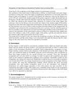
1.2 The geometry of the CDLI
As shown in figure 1, the geometry of the CDLI is optimized to cover the largest workspace
possible in a limited volume (i.e. the overall dimension of the complete CDLI) so as to avoid
cable interferences and to minimize human-cable interferences while the user is walking
(Perreault & Gosselin, 2008). It must be noted that due to the unilaterality of the actuation
principle, a cable-driven parallel platform needs at least seven cables in order to control a six
DOF platform. Since each platform has six DOF so as to emulate human gait (Yoon & Ryu,
2006) and all cable attachment points are chosen so as to reach an optimal workspace, each
haptic foot platform is actuated by eight cables.
The dimensions of the workspace along the X, Y and Z axis are respectively 2 metres, 0.6
metre and 1 metre, all within the overall dimensions of the complete CDLI whose size is
approximately 6.0 metres by 3.5 metres by 3.0 metres. These dimensions allow users to
perform a wide range of walking patterns.
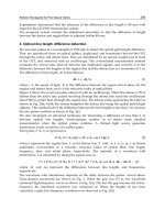
The model of the virtual foot in the virtual environment, shown in figure 2, is
mathematically related to the haptic foot platform by a translation vector and a rotation
matrix between their respective reference frames.
Fi
g
. 1. CAD model of the complete CDLI
taken from (Perreault & Gosselin, 2008)
Fi
g
. 2. Virtual foot models in contact with
virtual objects
1.3 Control Classes for Haptic Rendering
Two control classes are generally employed for haptic rendering on the platforms: an
impedance control class and an admittance control class similar to those described in
(Carignan & Cleary, 2000). Since both control classes use pose and wrench inputs, they are
CartesianControlofaCable-DrivenHapticMechanism 77
robot cooperation, some practical aspects of the software design for achieving a safe control
(for avoiding accidents and injuries) with a safety management plan are presented. Finally,
some stability issues are also developed specifically for the cable-driven parallel mechanism.
1.1 Review
The Cable-Driven Locomotion Interface (CDLI) design presented here is based on the
concept of programmable platforms with permanent foot contacts, such as Gait Master
(Iwata et al., 2001), (Onuki et al., 2007) and K-Walker or the Virtual Walking Machine in
(Yoon et al., 2004). CDLI employs two independent cable-driven haptic platforms
constrained in six degrees of freedom (Perreault & Gosselin, 2008). Each platform is attached
to a foot of the walker. Its control system and its geometry are designed so as to support a
wide range of walking patterns including left/right turns and going up/down slopes or
stairs that are either rigid or soft virtual surfaces or objects. In the following paragraphs, a
control algorithm made specifically for cable-driven platforms is presented to address the
issue of the interactions between the virtual foot models linked to the platforms and any
virtual object such as but not limited to uneven terrain.
Several concepts of locomotion interfaces have been developed in order to provide a better
feeling of immersion in a virtual environment and for automated walking rehabilitation. For
instance, the Rehabilitation Robot LOKOMAT (Bernhardt et al., 2005) uses a hybrid force-
position control method for which the force component adjusts the movement of an
actuated leg orthosis so as to influence the LOKOMAT's motion and to automate user gait-
pattern therapy. Such a control method is implemented in the context of the Patient-Driven
Motion Reinforcement paradigm. HapticWalker is a programmable robotic footplate device
that allows arbitrary foot movements during user gait training via specialized motion
generation algorithms (Schmidt et al., 2005). However these control strategies are not well
adapted to a CDLI as well as haptic rendering of contacts with any virtual objects or uneven
terrains. In fact, a CDLI shows substantial advantages over conventional locomotion
interfaces and has the potential to achieve better performances than other devices. For
instance, the haptic foot platform in a CDLI can reach higher accelerations and can move in
a larger workspace. Some designs involving cable-driven mechanisms were devised as the
primary haptic display in a virtual environment. For instance, cable-driven devices have
proven their efficiency as haptic interfaces in virtual sport training such as a tennis force
display (Kawamura et al., 1995) and a catch playing simulator (Morizono et al., 1997).
In this chapter, it is shown that a hybrid admittance/impedance strategy for controlling the
CDLI combines the benefits of both control classes and exploits the contact points geometry
and the physical properties (stiffness, friction, etc.) of the virtual surface colliding with the
virtual foot model. Within the CDLI control algorithm, the measured action wrenches
imposed by the walker's feet move the platforms while a virtual reaction wrench moves the
walker in the virtual environment in the event that a contact is detected between a virtual
object and the virtual foot model. The software also exploits the Newton Game Dynamics
TM
engine, labeled “Newton engine” in the following, for simulating rigid body interactions.
The second section of this chapter presents the software architecture for controlling the
haptic foot platform. The third and the fourth sections covers the development of the control
strategy for multiple-contact points geometry that is used for performing hybrid-controlled
interactions in a CDLI. The fifth one presents a custom physics engine developed under
QNX OS for force rendering on a haptic foot platform so as to manage soft object
interactions. This physics engine includes a Force Optimization Problem (FOP) to distribute
the wrench at each contact point uniformly and optimally. This custom engine is designed
to overcome some drawbacks of the Newton engine, such as transient force computation
and object penetration that occurs when a contact is detected between the virtual foot model
and a compliant surface. Finally, the last section of the chapter presents simulations of the
control strategy with the physics engines in normal gait walking conditions.
1.2 The geometry of the CDLI
As shown in figure 1, the geometry of the CDLI is optimized to cover the largest workspace
possible in a limited volume (i.e. the overall dimension of the complete CDLI) so as to avoid
cable interferences and to minimize human-cable interferences while the user is walking
(Perreault & Gosselin, 2008). It must be noted that due to the unilaterality of the actuation
principle, a cable-driven parallel platform needs at least seven cables in order to control a six
DOF platform. Since each platform has six DOF so as to emulate human gait (Yoon & Ryu,
2006) and all cable attachment points are chosen so as to reach an optimal workspace, each
haptic foot platform is actuated by eight cables.
The dimensions of the workspace along the X, Y and Z axis are respectively 2 metres, 0.6
metre and 1 metre, all within the overall dimensions of the complete CDLI whose size is
approximately 6.0 metres by 3.5 metres by 3.0 metres. These dimensions allow users to
perform a wide range of walking patterns.
The model of the virtual foot in the virtual environment, shown in figure 2, is
mathematically related to the haptic foot platform by a translation vector and a rotation
matrix between their respective reference frames.
Fig. 1. CAD model of the complete CDLI
taken from (Perreault & Gosselin, 2008)
Fi
g
. 2. Virtual foot models in contact with
virtual objects
1.3 Control Classes for Haptic Rendering
Two control classes are generally employed for haptic rendering on the platforms: an
impedance control class and an admittance control class similar to those described in
(Carignan & Cleary, 2000). Since both control classes use pose and wrench inputs, they are
AdvancesinHaptics78
instead defined by the output or the feedback loop. The properties of each approach are
compared in table 1. The Cobotic Hand Controller (Faulring et al., 2007) and the
HapticMaster (van der Linde & Lammertse, 2003) are both mechanisms that use admittance
control. On the other hand, the Excalibur (Adams et al., 2000) and the Phantom (McJunkin &
al., 2005) haptic devices have been designed as impedance displays that use impedance
control.
Indeed, two virtual object models could be defined: an admittance model and an impedance
model. Using linear circuit theory (quadripole or two-ports models), there are four possible
topologies described by the immitance matrices: the impedance matrix, the admittance
matrix, the hybrid matrix and the alternate hybrid matrix that the controller could manage
as described in (Adams & Hannaford, 1999).
The hybrid control strategy combining these two control classes (interacting with the both
virtual object models) ensure that free movements and contact with a rigid virtual object are
rendered realistically by the platforms. Section 4 describes a method for selecting the
appropriate control class using both the geometry of the contact points and the virtual object
properties.
Impedance-controlled system (impedance
control with force feedback)
Admittance-controlled system (admittance
control with position/velocity feedback)
Controls the wrench applied by the haptic
foot platform
Controls the pose or velocity of the haptic
device
Is subject to instabilities when the user
releases the device
Is subject to instabilities when the stiffness
of the user's legs increases
Can simulate highly compliant virtual
objects
Can simulate an unyielding virtual object
Table 1. Comparison of the control classes
1.4 Stability issues
The capability for a human to stabilize an unstable system or even to destabilize a stable
system is a recurrent problem in the haptic interface control. Two methods are developed in
the literature for stability analysis. The first one is based on human and environment models
(on-line or real-time computation of the muscle stiffness) in order to adjust an admittance
model in the controller that gives pose setpoints computed from the user applied wrench
measured at the end effector. This method consists in adjusting the control law for ensuring
stability of the system (Tsumugiwa et al., 2002). The analysis of the stability could then be
performed with different strategies such as Routh-Hurwitz, root-locus, Nyquist, Lyapunov
or μ-analysis among others. In the other case, the second method does not use any model.
This method analyses the transfer of energy inside the system like in (Hannaford & Ryu,
2002). On the other hand, there exist numerous stabilizing techniques such as those
exploited in adaptive or robust control.
A stable haptic system dissipates more energy than the overall control system produces.
However, this diminishes the realism of the haptic display as the dissipated energy
increases. It is therefore a trade-off between performance and transparency. In cable tension
control applications the dissipated energy should be compensated for so as to lead the
system toward an unstable regime. The stabilizing method uses a virtual damping
parameter in order to dissipate accumulated energy with a passivity observer (PO) and a
passivity controller (PC). This method was used also for compensating the delay on the
network.
Friction hysteresis in reel increases vibrations in the cables when the reel's mechanical parts
stick and slip. Furthermore, rigid contacts between the virtual object and the foot produce
discontinuities in cable tensions that have a tendency to create or emphasize cable
vibrations. Finally, the stiffness of the reel and of the mechanical structure should be at least
larger than the one of the virtual object so that mechanical deformation cannot generate
more instability. From this analysis, which excludes the electronic hardware, six types of
instability inside a hybrid control architecture for a Cable-Driven Mechanism can be
considered:
1. Cable vibration and tension discontinuities;
2. Mechanical design (stiffness of the overall mechanical structure including
motorized reel, friction hysteresis, actuator dynamic, encoder resolution, etc.);
3. Hybrid control architecture with uncertainty (Cheah et al., 2003) and with flexible
joint (Goldsmith et al., 1999);
4. Contacts with a stiff virtual object with one or more contact points (Lu & Song,
2008);
5. Interaction between a human and a mechanism (Duchaine & Gosselin, 2009) and
6. Time delay (latency) over the network (Changhyun et al., 2008).
2. Software Architecture for Control
The hardware architecture is composed of two components: a soft real-time module
implemented on a standard PC running Windows which manages the virtual environment
with a graphic rendering engine, and a hard real-time module implemented on a standard
PC running QNX whose primary tasks is to control and drive the cable-driven platforms
and a server that ensures intercommunication and synchronization between different
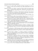
walkers. The software architecture is designed to exploit the above hardware and is thus
composed of the two components shown in figure 3: the Virtual Environment Manager and
the Controller Manager which are described in the next sections.
2.1 Virtual Environment Manager
The Virtual Environment Manager (VEM) is responsible for handling haptic objects (virtual
foot model and virtual object), a physics engine, and a virtual user (an avatar) whose feet are
shown to be moving in a virtual environment. The avatar therefore mimics the movements
of the user so that he or she can observe his actions in the virtual environment. The virtual
user defines the characteristics of the walker who can observe the virtual environment in
coherence with his feet. For the physics engine, Newton Game Dynamics
TM
is used as a slave
engine while the master physics engine is implemented on a second PC using QNX OS in
the controller manager as described in section 2.2. The communication between both physics
engines is ensured by a client communication interface and a server communication interface.
CartesianControlofaCable-DrivenHapticMechanism 79
instead defined by the output or the feedback loop. The properties of each approach are
compared in table 1. The Cobotic Hand Controller (Faulring et al., 2007) and the
HapticMaster (van der Linde & Lammertse, 2003) are both mechanisms that use admittance
control. On the other hand, the Excalibur (Adams et al., 2000) and the Phantom (McJunkin &
al., 2005) haptic devices have been designed as impedance displays that use impedance
control.
Indeed, two virtual object models could be defined: an admittance model and an impedance
model. Using linear circuit theory (quadripole or two-ports models), there are four possible
topologies described by the immitance matrices: the impedance matrix, the admittance
matrix, the hybrid matrix and the alternate hybrid matrix that the controller could manage
as described in (Adams & Hannaford, 1999).
The hybrid control strategy combining these two control classes (interacting with the both
virtual object models) ensure that free movements and contact with a rigid virtual object are
rendered realistically by the platforms. Section 4 describes a method for selecting the
appropriate control class using both the geometry of the contact points and the virtual object
properties.
Impedance-controlled system (impedance
control with force feedback)
Admittance-controlled system (admittance
control with position/velocity feedback)
Controls the wrench applied by the haptic
foot platform
Controls the pose or velocity of the haptic
device
Is subject to instabilities when the user
releases the device
Is subject to instabilities when the stiffness
of the user's legs increases
Can simulate highly compliant virtual
objects
Can simulate an unyielding virtual object
Table 1. Comparison of the control classes
1.4 Stability issues
The capability for a human to stabilize an unstable system or even to destabilize a stable
system is a recurrent problem in the haptic interface control. Two methods are developed in
the literature for stability analysis. The first one is based on human and environment models
(on-line or real-time computation of the muscle stiffness) in order to adjust an admittance
model in the controller that gives pose setpoints computed from the user applied wrench
measured at the end effector. This method consists in adjusting the control law for ensuring
stability of the system (Tsumugiwa et al., 2002). The analysis of the stability could then be
performed with different strategies such as Routh-Hurwitz, root-locus, Nyquist, Lyapunov
or μ-analysis among others. In the other case, the second method does not use any model.
This method analyses the transfer of energy inside the system like in (Hannaford & Ryu,
2002). On the other hand, there exist numerous stabilizing techniques such as those
exploited in adaptive or robust control.
A stable haptic system dissipates more energy than the overall control system produces.
However, this diminishes the realism of the haptic display as the dissipated energy
increases. It is therefore a trade-off between performance and transparency. In cable tension
control applications the dissipated energy should be compensated for so as to lead the
system toward an unstable regime. The stabilizing method uses a virtual damping
parameter in order to dissipate accumulated energy with a passivity observer (PO) and a
passivity controller (PC). This method was used also for compensating the delay on the
network.
Friction hysteresis in reel increases vibrations in the cables when the reel's mechanical parts
stick and slip. Furthermore, rigid contacts between the virtual object and the foot produce
discontinuities in cable tensions that have a tendency to create or emphasize cable
vibrations. Finally, the stiffness of the reel and of the mechanical structure should be at least
larger than the one of the virtual object so that mechanical deformation cannot generate
more instability. From this analysis, which excludes the electronic hardware, six types of
instability inside a hybrid control architecture for a Cable-Driven Mechanism can be
considered:
1. Cable vibration and tension discontinuities;
2. Mechanical design (stiffness of the overall mechanical structure including
motorized reel, friction hysteresis, actuator dynamic, encoder resolution, etc.);
3. Hybrid control architecture with uncertainty (Cheah et al., 2003) and with flexible
joint (Goldsmith et al., 1999);
4. Contacts with a stiff virtual object with one or more contact points (Lu & Song,
2008);
5. Interaction between a human and a mechanism (Duchaine & Gosselin, 2009) and
6. Time delay (latency) over the network (Changhyun et al., 2008).
2. Software Architecture for Control
The hardware architecture is composed of two components: a soft real-time module
implemented on a standard PC running Windows which manages the virtual environment
with a graphic rendering engine, and a hard real-time module implemented on a standard
PC running QNX whose primary tasks is to control and drive the cable-driven platforms
and a server that ensures intercommunication and synchronization between different
walkers. The software architecture is designed to exploit the above hardware and is thus
composed of the two components shown in figure 3: the Virtual Environment Manager and
the Controller Manager which are described in the next sections.
2.1 Virtual Environment Manager
The Virtual Environment Manager (VEM) is responsible for handling haptic objects (virtual
foot model and virtual object), a physics engine, and a virtual user (an avatar) whose feet are
shown to be moving in a virtual environment. The avatar therefore mimics the movements
of the user so that he or she can observe his actions in the virtual environment. The virtual
user defines the characteristics of the walker who can observe the virtual environment in
coherence with his feet. For the physics engine, Newton Game Dynamics
TM
is used as a slave
engine while the master physics engine is implemented on a second PC using QNX OS in
the controller manager as described in section 2.2. The communication between both physics
engines is ensured by a client communication interface and a server communication interface.
AdvancesinHaptics80
The Haptic Scene Manager (HSM) is the main interface with which the virtual environment is
built and configured. The HSM is responsible for configuring the Newton engine according
to the simulation requirements.
Fig. 3. Software architecture
It is also responsible for the creation, set up, and destruction of virtual objects having a
haptic presence in the environment. Besides the HSM, the haptic module uses two other
managers for the hands (hand manager) and feet (foot manager that define the avatar). The foot
manager, which is connected to the virtual user, communicates with the controller manager
using a TCP/IP connection. Over this communication link, the Newton engine provides the
contact points between each virtual foot model and the virtual object to the controller
manager and also provides the normal/tangent vectors to these contact points as well as the
penetration into the virtual object. Conversely, the controller manager responds to these
inputs by providing the foot manager with the pose and the speed of the haptic foot platform
resulting from the contact, as well as the total wrench computed by the custom physics
engine which then moves the virtual foot model and the virtual object in the scene.
The communication link between the VEM and the controller manager must support a
minimum transmission rate of approximately 100 Hz in order to transfer a burst of 512 bytes
with a maximum latency of one millisecond. Although there are hardware solutions
satisfying these requirements, the main issue still remains the latency of the asynchronous
process which is only executed whenever possible. Some solutions for resolving
communication bandwidth limitations are given in (Sakr et al., 2009), where a prediction
approach is exploited with the knowledge of human haptic perception (Just Noticeable
Differences of Weber's law). The definition of a deadband is used for data reduction. This
deadband consists of velocity and pose threshold values where there are no significant new
informations. In the proposed system described in this chapter, the quantity of data
transmitted over the network is based on the selection of meaningful contact points from
those evaluated by the Newton engine. In fact, only three points are required by the
controller manager to define the control class that will be applied in the appropriated DOF.
2.2 Controller Manager
The controller manager runs two processes: a hard real-time periodic process (labeled control
algorithm process) responsible for the hybrid control algorithm, and a soft real-time
asynchronous process that manages the virtual environment updates between the foot
manager and the control algorithm process. The periodic process can be pre-empted any time
by the asynchronous process. The rate of the periodic process for controlling the actuators
and the sampling rate achieved for wrench sensing are both set at a multiple of the analog
input signal number and has a minimal rate of 500 Hz, and in the best case, 1 kHz.
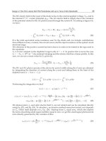
The virtual torquer in tandem with the control algorithm process runs the master physics
engine (labeled Haptic Display Rendering (HDR) in figure 4) as well as a washout filter that
maintains the walker at the centre of the workspace using a variable impedance model and
position feedback as described in (Yoon & Ryu, 2006) and (Yoon. & Ryu, 2009).
Fig. 4. Simplified control algorithm process with interactions of both physics engines
The control algorithm process, detailed in figure 4, accepts one input (the output of a 6 DOF
wrench sensor) and produces two outputs (cable tensions τ
c
and platform poses P
PF
).
The appropriate reaction wrench h
r
is computed from the interaction between both
physics engines. These engines also determine whether the degrees of freedom for each
platform should be controlled in impedance or in admittance. Depending on the selected
control class, the 6 DOF wrench sensor can produce, an action wrench h
a
which moves
each platform using a hybrid control scheme.
The total wrench h
c
applied at the centre of mass of the platform is balanced with
positive cable tensions using an Optimal Tension Distribution (OTD) algorithm as described
in (Fang et al., 2004). The result being a set of equilibrium tension values τ
c
, called the
setpoint, that the cable tension controllers then attempt to follow. The pose of each platform
is computed with the Direct Kinematic Problem (DKP) algorithm using the lengths of the
cables ρ
m
as input.
Since a virtual object can be rigid or soft, two physics engines are implemented to ensure a
general approach that allows the physical reactions between the platforms and virtual
objects to be adjusted. The HDR decides which reaction wrench computed by both engines
must be transferred to the hybrid control. This choice depends both on the properties of the
CartesianControlofaCable-DrivenHapticMechanism 81
The Haptic Scene Manager (HSM) is the main interface with which the virtual environment is
built and configured. The HSM is responsible for configuring the Newton engine according
to the simulation requirements.
Fig. 3. Software architecture
It is also responsible for the creation, set up, and destruction of virtual objects having a
haptic presence in the environment. Besides the HSM, the haptic module uses two other
managers for the hands (hand manager) and feet (foot manager that define the avatar). The foot
manager, which is connected to the virtual user, communicates with the controller manager
using a TCP/IP connection. Over this communication link, the Newton engine provides the
contact points between each virtual foot model and the virtual object to the controller
manager and also provides the normal/tangent vectors to these contact points as well as the
penetration into the virtual object. Conversely, the controller manager responds to these
inputs by providing the foot manager with the pose and the speed of the haptic foot platform
resulting from the contact, as well as the total wrench computed by the custom physics
engine which then moves the virtual foot model and the virtual object in the scene.
The communication link between the VEM and the controller manager must support a
minimum transmission rate of approximately 100 Hz in order to transfer a burst of 512 bytes
with a maximum latency of one millisecond. Although there are hardware solutions
satisfying these requirements, the main issue still remains the latency of the asynchronous
process which is only executed whenever possible. Some solutions for resolving
communication bandwidth limitations are given in (Sakr et al., 2009), where a prediction
approach is exploited with the knowledge of human haptic perception (Just Noticeable
Differences of Weber's law). The definition of a deadband is used for data reduction. This
deadband consists of velocity and pose threshold values where there are no significant new
informations. In the proposed system described in this chapter, the quantity of data
transmitted over the network is based on the selection of meaningful contact points from
those evaluated by the Newton engine. In fact, only three points are required by the
controller manager to define the control class that will be applied in the appropriated DOF.
2.2 Controller Manager
The controller manager runs two processes: a hard real-time periodic process (labeled control
algorithm process) responsible for the hybrid control algorithm, and a soft real-time
asynchronous process that manages the virtual environment updates between the foot
manager and the control algorithm process. The periodic process can be pre-empted any time
by the asynchronous process. The rate of the periodic process for controlling the actuators
and the sampling rate achieved for wrench sensing are both set at a multiple of the analog
input signal number and has a minimal rate of 500 Hz, and in the best case, 1 kHz.
The virtual torquer in tandem with the control algorithm process runs the master physics
engine (labeled Haptic Display Rendering (HDR) in figure 4) as well as a washout filter that
maintains the walker at the centre of the workspace using a variable impedance model and
position feedback as described in (Yoon & Ryu, 2006) and (Yoon. & Ryu, 2009).
Fig. 4. Simplified control algorithm process with interactions of both physics engines
The control algorithm process, detailed in figure 4, accepts one input (the output of a 6 DOF
wrench sensor) and produces two outputs (cable tensions τ
c
and platform poses P
PF
).
The appropriate reaction wrench h
r
is computed from the interaction between both
physics engines. These engines also determine whether the degrees of freedom for each
platform should be controlled in impedance or in admittance. Depending on the selected
control class, the 6 DOF wrench sensor can produce, an action wrench h
a
which moves
each platform using a hybrid control scheme.
The total wrench h
c
applied at the centre of mass of the platform is balanced with
positive cable tensions using an Optimal Tension Distribution (OTD) algorithm as described
in (Fang et al., 2004). The result being a set of equilibrium tension values τ
c
, called the
setpoint, that the cable tension controllers then attempt to follow. The pose of each platform
is computed with the Direct Kinematic Problem (DKP) algorithm using the lengths of the
cables ρ
m
as input.
Since a virtual object can be rigid or soft, two physics engines are implemented to ensure a
general approach that allows the physical reactions between the platforms and virtual
objects to be adjusted. The HDR decides which reaction wrench computed by both engines
must be transferred to the hybrid control. This choice depends both on the properties of the
AdvancesinHaptics82
virtual object and on the contact points geometry. The contact point detection and the
associated normal vector at the interface between a virtual object and a virtual foot model is
evaluated by the Newton engine and dynamic proxy objects. The HDR exploits these values
to compute its own reaction wrench h
r
and for selecting which control class to use in order
to get the best haptic rendering.
2.3 Cartesian Compensations
Mechanism transparency is crucial when a walker has to use a mechanical device inside a
virtual environment. Indeed, in the virtual world, the user must be able to forget the fact that
he is attached and that he is using a real device. Only the simulated physics (such as friction
between foot and virtual object) inside the virtual environment must be reproduced under the
user's foot. In order for this to happen, it is very important to know the exact behaviour of the
mechanism at any time. This is made possible by knowing the dynamics of the device.
In a locomotion interface, the inertia and weight of platforms and sensors must be
compensated for in order to increase the realism of the haptic display to the user. Therefore,
h
c
not only includes the variable load h
a
applied by a walker's foot on the platform and the
set of wrenches h
r
computed from the interaction between walker's feet and its virtual
environment, but also the effect of the weight h
wPF
and inertia h
iPF
of the
platform and wrench sensors. For impedance control with force feedback, an additional h
r
is
added for haptic rendering of virtual contact between the platform and the virtual object.
Fig. 5. Reference frame of the platform
The compensation for the mechanism inertia and weight (platforms and sensors altogether)
is computed by dynamic wrenches h
iPF
and h
wPF
respectively. Since there are two working
frames, the inertial frame G
g
and the moving frame attached to the end-effector G
PF
(as
described in figure 5), and no deformation is permitted to the platform, h
iPF
can be defined
as follows:
,
,
(1)
where the scalar noted m represents the mass of the platform, the vector noted a
cm
represents the acceleration vector of the centre of mass of the platform in the inertial frame
(i.e. the global reference frame), I
cm
is the inertia matrix of the platform to its centre
of mass and defined in the mobile frame G
PF
(this matrix is constant since the mobile frame
is fixed to the platform), ω is the angular velocity vector of the moving frame G
PF
compared
to the inertial frame G
g
, and r
cm
is the vector connecting the origin of the moving frame to
the centre of mass of the platform in G
PF
.
The value of h
iPF
is negative since it removes the inertia of the moving mechanism. Also the
evaluation of a
cm
with a low level of noise could be difficult with a low resolution of
quadrature encoder inside the reel. This value should be evaluated with a six axis
accelerometer/gyroscope module installed near the centre of mass. For the system
presented in this chapter, it is not recommended to evaluate a
cm
with the wrench sensor
since the wrench sensor is used in the hybrid control.
Finally, to complete the part of dynamic relations related to the platform of the mechanism,
it is needed to describe the wrench of the weight of the platform h
wPF
. Thus, this relation is
defined as follows:
,
(2)
where the vector g is the gravitational acceleration vector. As for the inertia of the motors
and reels, they are accounted for by the cable tension controllers which also consider the
effects of friction at low speed in order to accelerate the responses of their respective control
loop.
2.4 Optimal Tension Distribution
Since each platform is driven by n-6 redundant cables, it is important that the tension be
distributed among them according to kinematic and dynamic conditions so as to minimize
the actuation power over all actuators (Hassan & Khajepour, 2008). It is desired to maintain
the tension in the cables above a minimum threshold value τ
min
to limit cable sagging. Such
a threshold must be greater than the minimal tension set by the precision of the acquisition
system combined with a performance criterion obtained from cable behaviour (Otis et al.,
2009a). Actuators (i.e. reel, motor and cable) are also limited by a maximum torque τ
max
which helps to avoid control problems. Hence, the following force distribution method is
proposed to avoid cable sagging as well as excessive mechanical deformation of the CDLI:
(3)
CartesianControlofaCable-DrivenHapticMechanism 83
virtual object and on the contact points geometry. The contact point detection and the
associated normal vector at the interface between a virtual object and a virtual foot model is
evaluated by the Newton engine and dynamic proxy objects. The HDR exploits these values
to compute its own reaction wrench h
r
and for selecting which control class to use in order
to get the best haptic rendering.
2.3 Cartesian Compensations
Mechanism transparency is crucial when a walker has to use a mechanical device inside a
virtual environment. Indeed, in the virtual world, the user must be able to forget the fact that
he is attached and that he is using a real device. Only the simulated physics (such as friction
between foot and virtual object) inside the virtual environment must be reproduced under the
user's foot. In order for this to happen, it is very important to know the exact behaviour of the
mechanism at any time. This is made possible by knowing the dynamics of the device.
In a locomotion interface, the inertia and weight of platforms and sensors must be
compensated for in order to increase the realism of the haptic display to the user. Therefore,
h
c
not only includes the variable load h
a
applied by a walker's foot on the platform and the
set of wrenches h
r
computed from the interaction between walker's feet and its virtual
environment, but also the effect of the weight h
wPF
and inertia h
iPF
of the
platform and wrench sensors. For impedance control with force feedback, an additional h
r
is
added for haptic rendering of virtual contact between the platform and the virtual object.
Fig. 5. Reference frame of the platform
The compensation for the mechanism inertia and weight (platforms and sensors altogether)
is computed by dynamic wrenches h
iPF
and h
wPF
respectively. Since there are two working
frames, the inertial frame G
g
and the moving frame attached to the end-effector G
PF
(as
described in figure 5), and no deformation is permitted to the platform, h
iPF
can be defined
as follows:
,
,
(1)
where the scalar noted m represents the mass of the platform, the vector noted a
cm
represents the acceleration vector of the centre of mass of the platform in the inertial frame
(i.e. the global reference frame), I
cm
is the inertia matrix of the platform to its centre
of mass and defined in the mobile frame G
PF
(this matrix is constant since the mobile frame
is fixed to the platform), ω is the angular velocity vector of the moving frame G
PF
compared
to the inertial frame G
g
, and r
cm
is the vector connecting the origin of the moving frame to
the centre of mass of the platform in G
PF
.
The value of h
iPF
is negative since it removes the inertia of the moving mechanism. Also the
evaluation of a
cm
with a low level of noise could be difficult with a low resolution of
quadrature encoder inside the reel. This value should be evaluated with a six axis
accelerometer/gyroscope module installed near the centre of mass. For the system
presented in this chapter, it is not recommended to evaluate a
cm
with the wrench sensor
since the wrench sensor is used in the hybrid control.
Finally, to complete the part of dynamic relations related to the platform of the mechanism,
it is needed to describe the wrench of the weight of the platform h
wPF
. Thus, this relation is
defined as follows:
,
(2)
where the vector g is the gravitational acceleration vector. As for the inertia of the motors
and reels, they are accounted for by the cable tension controllers which also consider the
effects of friction at low speed in order to accelerate the responses of their respective control
loop.
2.4 Optimal Tension Distribution
Since each platform is driven by n-6 redundant cables, it is important that the tension be
distributed among them according to kinematic and dynamic conditions so as to minimize
the actuation power over all actuators (Hassan & Khajepour, 2008). It is desired to maintain
the tension in the cables above a minimum threshold value τ
min
to limit cable sagging. Such
a threshold must be greater than the minimal tension set by the precision of the acquisition
system combined with a performance criterion obtained from cable behaviour (Otis et al.,
2009a). Actuators (i.e. reel, motor and cable) are also limited by a maximum torque τ
max
which helps to avoid control problems. Hence, the following force distribution method is
proposed to avoid cable sagging as well as excessive mechanical deformation of the CDLI:
(3)
AdvancesinHaptics84
(4)
where h
c
represents the forces and torques that are applied on a single platform (i.e. the
wrench applied by the cables on that platform), τ
i
is the tension vector of the ith (of n) cable,
W is the pose-dependent wrench matrix computed by the platform Jacobian matrix that
links Cartesian to articular velocities, G is a weighting matrix with its diagonal elements
such that g
i
= 1 for all i, where the mathematical derivation of (3) is presented in (Barrette &
Gosselin, 2005) and an application is described in (Perreault & Gosselin, 2008).
2.5 Human safety and security management plan
In the context of a human and a mechanism interacting within the same workspace, safety
for human user is one of the utmost importance issues to be considered for avoiding
accidents and injuries. The overall control algorithm process has a safety manager with an
error handler that was designed with the help of a risk study. Each component of the
software must have self-testing capabilities (or BIST for Build-In Self Test) for a general
system test planning for the purpose of quality assurance (QA) and safety management. A
Hardware-in-the-loop (HIL) simulator could be implemented as a way for running some
parts of the BIST and partially control the platform. Documentations can be found in the
IEEE 829 Standard for Software Test Documentation, CSA Z432-04 and ISO 14121. For
Cable-Driven Mechanism applied to haptic applications, a minimum of four safety issues
must be considered and documented:
1. Sensors reliability or fault tolerant (cable cut or failure by fatigue);
2. Mechanical interference like cable interference and platform interference with other
parts of the mechanism or the user (Otis et al., 2009a);
3. Workspace limitations when the platform is going outside of its workspace;
4. Human and robot interaction like :
The mechanical device that safely disconnects the user from the mechanism
when the mechanism is out of control (Lauzier & Gosselin, 2009) and,
The safety tether which maintains the equilibrium of the user when walking,
falling or when the mechanism is out of control (Ottaviano et al., 2008), (Grow
& Hollerbach, 2006).
Other safety aspects of the system must also be guaranteed. For example, the system must
manage any sensor destruction and limits on control values (cable length, maximal and
minimal cable tension, maximal current send to the motor, maximum wrench generated
from the physics engine, etc.). Finally, a watchdog timer is included to ensure that the
control algorithm process is executed within the prescribed period of the periodic process
within an error of 5%. This watchdog and the timing period are set using a hardware
interrupt implemented on a data acquisition board that is independent from the software to
avoid control failure and to ensure hard real-time response. For computing derivative and
for reducing noise on this value, the algorithm should consider the time shift generated by
the latency (the 5% error on the prescribed period) of the OS context switching (or other
process running).
3. Admittance/Impedance/Inertial-Wrench Hybrid Control
Hybrid control is a general approach that exhibits the combined advantages of impedance,
admittance, and inertial-wrench control (or more precisely a null wrench control). The
structure of the admittance/impedance hybrid control for one platform is shown in figure 4
and is detailed in figure 6. Two identical control structures are implemented, one per
platform. The selection of the control class for each DOF of the platform is achieved by the П
matrix. The state of the П matrix depends on the orientation of contact points
geometry and the orientations of the platform.
When the reaction force h
r
is null and the impedance control class is selected by the П
matrix, one simply chooses a null force control scheme with an open gain loop G
ch
=K.
Otherwise, impedance or admittance control is applied on the desired DOF for each
platform. Admittance control could be performed by velocity or position feedback which
could produce different experimental results, as described in (Duchaine & Gosselin, 2007).
The desired platform positions P
PFd
(or the desired velocities) are defined by the contact
points given by the Newton engine. As the strategy used by the Newton engine, a wrench
h
p
must be added to the admittance control to avoid any large penetration inside a virtual
object when a collision detection may have been missed because the refresh rate is not
performed in time. This strategy also avoids the computation of a new set of contact points
as the foot enters the object. In the Newton engine, the wrench h
p
is computed with an
impedance model of the object and must be controlled in the physics engine since the
command is a null penetration for a rigid contact. From figure 6, the wrench T
-
I
cm
h
o
to be
computed by the hybrid controller is defined by equations (5) to (8) :
T h ( (P P ) h )
-I
cm o cp p
PF
PFd
GΠ
with,
(5)
(6)
(7)
(8)
where G
cp
is a standard filter that controls the desired position P
PFd
(or the desired velocity)
of the platform (P
PF
is the measured position), Q
c
is the rotation matrix between the
contact points reference frame G
c
and the platform reference frame G
PF
. Q is the
rotation matrix between reference frame G
PF
and its global counterpart G
g
, which is
computed by the DKP with the cable lengths ρ
m
. G
ch
is the wrench controller which should
CartesianControlofaCable-DrivenHapticMechanism 85
(4)
where h
c
represents the forces and torques that are applied on a single platform (i.e. the
wrench applied by the cables on that platform), τ
i
is the tension vector of the ith (of n) cable,
W is the pose-dependent wrench matrix computed by the platform Jacobian matrix that
links Cartesian to articular velocities, G is a weighting matrix with its diagonal elements
such that g
i
= 1 for all i, where the mathematical derivation of (3) is presented in (Barrette &
Gosselin, 2005) and an application is described in (Perreault & Gosselin, 2008).
2.5 Human safety and security management plan
In the context of a human and a mechanism interacting within the same workspace, safety
for human user is one of the utmost importance issues to be considered for avoiding
accidents and injuries. The overall control algorithm process has a safety manager with an
error handler that was designed with the help of a risk study. Each component of the
software must have self-testing capabilities (or BIST for Build-In Self Test) for a general
system test planning for the purpose of quality assurance (QA) and safety management. A
Hardware-in-the-loop (HIL) simulator could be implemented as a way for running some
parts of the BIST and partially control the platform. Documentations can be found in the
IEEE 829 Standard for Software Test Documentation, CSA Z432-04 and ISO 14121. For
Cable-Driven Mechanism applied to haptic applications, a minimum of four safety issues
must be considered and documented:
1. Sensors reliability or fault tolerant (cable cut or failure by fatigue);
2. Mechanical interference like cable interference and platform interference with other
parts of the mechanism or the user (Otis et al., 2009a);
3. Workspace limitations when the platform is going outside of its workspace;
4. Human and robot interaction like :
The mechanical device that safely disconnects the user from the mechanism
when the mechanism is out of control (Lauzier & Gosselin, 2009) and,
The safety tether which maintains the equilibrium of the user when walking,
falling or when the mechanism is out of control (Ottaviano et al., 2008), (Grow
& Hollerbach, 2006).
Other safety aspects of the system must also be guaranteed. For example, the system must
manage any sensor destruction and limits on control values (cable length, maximal and
minimal cable tension, maximal current send to the motor, maximum wrench generated
from the physics engine, etc.). Finally, a watchdog timer is included to ensure that the
control algorithm process is executed within the prescribed period of the periodic process
within an error of 5%. This watchdog and the timing period are set using a hardware
interrupt implemented on a data acquisition board that is independent from the software to
avoid control failure and to ensure hard real-time response. For computing derivative and
for reducing noise on this value, the algorithm should consider the time shift generated by
the latency (the 5% error on the prescribed period) of the OS context switching (or other
process running).
3. Admittance/Impedance/Inertial-Wrench Hybrid Control
Hybrid control is a general approach that exhibits the combined advantages of impedance,
admittance, and inertial-wrench control (or more precisely a null wrench control). The
structure of the admittance/impedance hybrid control for one platform is shown in figure 4
and is detailed in figure 6. Two identical control structures are implemented, one per
platform. The selection of the control class for each DOF of the platform is achieved by the П
matrix. The state of the П matrix depends on the orientation of contact points
geometry and the orientations of the platform.
When the reaction force h
r
is null and the impedance control class is selected by the П
matrix, one simply chooses a null force control scheme with an open gain loop G
ch
=K.
Otherwise, impedance or admittance control is applied on the desired DOF for each
platform. Admittance control could be performed by velocity or position feedback which
could produce different experimental results, as described in (Duchaine & Gosselin, 2007).
The desired platform positions P
PFd
(or the desired velocities) are defined by the contact
points given by the Newton engine. As the strategy used by the Newton engine, a wrench
h
p
must be added to the admittance control to avoid any large penetration inside a virtual
object when a collision detection may have been missed because the refresh rate is not
performed in time. This strategy also avoids the computation of a new set of contact points
as the foot enters the object. In the Newton engine, the wrench h
p
is computed with an
impedance model of the object and must be controlled in the physics engine since the
command is a null penetration for a rigid contact. From figure 6, the wrench T
-
I
cm
h
o
to be
computed by the hybrid controller is defined by equations (5) to (8) :
T h ( (P P ) h )
-I
cm o cp p
PF
PFd
GΠ
with,
(5)
(6)
(7)
(8)
where G
cp
is a standard filter that controls the desired position P
PFd
(or the desired velocity)
of the platform (P
PF
is the measured position), Q
c
is the rotation matrix between the
contact points reference frame G
c
and the platform reference frame G
PF
. Q is the
rotation matrix between reference frame G
PF
and its global counterpart G
g
, which is
computed by the DKP with the cable lengths ρ
m
. G
ch
is the wrench controller which should
AdvancesinHaptics86
be set high enough (bounded by the appropriate stability criteria) to reduce the errors
caused by the dynamics and friction of the cable-driven platform and of the motorized reels.
A transfer matrix T
cm
is used for computing the output wrench at the centre of mass of the
platform since all haptic wrenches are under the foot and the OTD uses the centre of mass as
its reference. Also, to prevent the platform form sticking to the contact point (i.e. when the
hybrid control is oscillating between admittance and impedance), the action wrench h
a
is
added to the output of the hybrid controller with a gain K
h
. This gain and the two Cartesian
controllers must consider the geometry of the mechanism and stability margins. In a Cable-
Driven Mechanism, an anisotropy geometry could be designed and the control would need
more energy in some DOF than other for obtaining the same transparency. Note that the
initial conditions of the integrators and the filters inside both G
ch
and G
cp
must be adjusted
for avoiding bouncing and instability. Furthermore, in some circumstances, kinematics and
dynamics uncertainties must be considered in a hybrid control as described in (Cheah et al.,
2003).
Fig. 6. Admittance/Impedance/Null Force Hybrid Control
The selection between control classes is achieved by the diagonal selection matrix S
c
(1 or 0 on the diagonal and other values are set to 0) and is evaluated in the contact point
reference frame G
c
. The values on the diagonal of matrix S
c
depend on friction, contact
points geometry, and calibration based on experiments. A second selection matrix, П
o
,
defined in equation (9), is used to compute the force at each contact point by selecting the
DOF under constraint using the Force Optimization Problem (FOP) algorithm defined in
section 5.2:
(9)
Thus, a 0 on the diagonal of matrix S
o
allows a null force control by providing a
corresponding null component for the wrench in contact points reference frame G
c
. These
two selection matrices (S
c
and S
o
) are thereby quite similar in function, albeit not identical.
4. Definition of the multi-contact points geometry
Since the control strategy exploits two physics engines (Newton engine and HDR), each
engine can control a given platform's DOF either in admittance or in impedance
simultaneously. The virtual object properties and the contact points geometry are the criteria
that determine the appropriate control class using the selection matrix П that satisfies the
following properties:
1. For a collision between a virtual foot model and a rigid virtual object for which a
friction model is implemented, the selection could be based on the geometry
described by the contact points between the virtual object and the virtual foot
model;
2. To simulate friction, impedance control with force feedback could be chosen
because there is a tangent force at the contact point reacting to an applied force
from the user;
3. For compliant virtual objects, impedance control could be chosen and
4. Movement in free space could be simulated by a null force control, a special case of
impedance control when some components of h
r
are equal to 0.
The favoured method used for selecting a given control class is a multi-contact points
strategy (shown in figure 7) that emphasizes control advantages relating to the simulation of
rigid virtual objects which includes a friction model. Contact points are computed as the
minimum set of points that completely define the boundary of the intersection between a
virtual foot model and a given virtual object. They are represented in the Newton engine in
conjunction with a corresponding set of normal vectors. For a haptic foot platform, a set of
points whose relative distances are within ten millimetres can be viewed by the control
algorithm as a single point.
The multi-contat points strategy used in this case involves the direction of the user-applied
wrench for each foot: if a component of the measured wrench h
a
is in the same direction as a
normal vector describing contact points geometry, which means that the user pushes on the
virtual object, this direction (or DOF) is then constrained by admittance control for rigid
virtual objects; otherwise either null force control is selected to simulate free movement (i.e.
the contact point is eliminated) or impedance control is employed to simulate friction. In the
case of a soft virtual object, impedance control is selected in the direction normal to the
contact points geometry. In figure 7, the normal vector describing contact points geometry is
along the z
c
axis.
Fig. 7. Contact points description for the three cases
CartesianControlofaCable-DrivenHapticMechanism 87
be set high enough (bounded by the appropriate stability criteria) to reduce the errors
caused by the dynamics and friction of the cable-driven platform and of the motorized reels.
A transfer matrix T
cm
is used for computing the output wrench at the centre of mass of the
platform since all haptic wrenches are under the foot and the OTD uses the centre of mass as
its reference. Also, to prevent the platform form sticking to the contact point (i.e. when the
hybrid control is oscillating between admittance and impedance), the action wrench h
a
is
added to the output of the hybrid controller with a gain K
h
. This gain and the two Cartesian
controllers must consider the geometry of the mechanism and stability margins. In a Cable-
Driven Mechanism, an anisotropy geometry could be designed and the control would need
more energy in some DOF than other for obtaining the same transparency. Note that the
initial conditions of the integrators and the filters inside both G
ch
and G
cp
must be adjusted
for avoiding bouncing and instability. Furthermore, in some circumstances, kinematics and
dynamics uncertainties must be considered in a hybrid control as described in (Cheah et al.,
2003).
Fig. 6. Admittance/Impedance/Null Force Hybrid Control
The selection between control classes is achieved by the diagonal selection matrix S
c
(1 or 0 on the diagonal and other values are set to 0) and is evaluated in the contact point
reference frame G
c
. The values on the diagonal of matrix S
c
depend on friction, contact
points geometry, and calibration based on experiments. A second selection matrix, П
o
,
defined in equation (9), is used to compute the force at each contact point by selecting the
DOF under constraint using the Force Optimization Problem (FOP) algorithm defined in
section 5.2:
(9)
Thus, a 0 on the diagonal of matrix S
o
allows a null force control by providing a
corresponding null component for the wrench in contact points reference frame G
c
. These
two selection matrices (S
c
and S
o
) are thereby quite similar in function, albeit not identical.
4. Definition of the multi-contact points geometry
Since the control strategy exploits two physics engines (Newton engine and HDR), each
engine can control a given platform's DOF either in admittance or in impedance
simultaneously. The virtual object properties and the contact points geometry are the criteria
that determine the appropriate control class using the selection matrix П that satisfies the
following properties:
1. For a collision between a virtual foot model and a rigid virtual object for which a
friction model is implemented, the selection could be based on the geometry
described by the contact points between the virtual object and the virtual foot
model;
2. To simulate friction, impedance control with force feedback could be chosen
because there is a tangent force at the contact point reacting to an applied force
from the user;
3. For compliant virtual objects, impedance control could be chosen and
4. Movement in free space could be simulated by a null force control, a special case of
impedance control when some components of h
r
are equal to 0.
The favoured method used for selecting a given control class is a multi-contact points
strategy (shown in figure 7) that emphasizes control advantages relating to the simulation of
rigid virtual objects which includes a friction model. Contact points are computed as the
minimum set of points that completely define the boundary of the intersection between a
virtual foot model and a given virtual object. They are represented in the Newton engine in
conjunction with a corresponding set of normal vectors. For a haptic foot platform, a set of
points whose relative distances are within ten millimetres can be viewed by the control
algorithm as a single point.
The multi-contat points strategy used in this case involves the direction of the user-applied
wrench for each foot: if a component of the measured wrench h
a
is in the same direction as a
normal vector describing contact points geometry, which means that the user pushes on the
virtual object, this direction (or DOF) is then constrained by admittance control for rigid
virtual objects; otherwise either null force control is selected to simulate free movement (i.e.
the contact point is eliminated) or impedance control is employed to simulate friction. In the
case of a soft virtual object, impedance control is selected in the direction normal to the
contact points geometry. In figure 7, the normal vector describing contact points geometry is
along the z
c
axis.
Fig. 7. Contact points description for the three cases
AdvancesinHaptics88
The theory, in the following, applies only for contacts with relatively low deformation.
When the deformation is non-linear, alternative methods must be used. In the particular
case of a linear deformation, there are three possibilities for which the constraints must be
evaluated: the case of a single contact point (section 4.1), two contact points (section 4.2),
and three or more contact points (section 4.3) when the wrench h
a
is in the same direction as
the normal vector describing contact points geometry.
4.1 Single contact point
The presence of a single contact point is a special case where the contact detection algorithm
of the physics engine only finds points that are all situated within a minimal distance, and
thus do not generate enough supporting action to some DOFs of the platform that would
otherwise have been constrained. This case therefore only constrains the platform in the
direction of the normal vector n
c
defined by the tangent plane of the virtual object's surface
at the contact point, assuming that friction vectors lie in this plane; the other directions are
left unconstrained, i.e. free to move around, as shown in figure 7a). Thus, S
c
[2][2] is set to
one and all other values are set to zero, since the z
c
axis is set in the normal direction of the
contact point.
It must be noted that the determination of rotation matrix Q
c
is difficult because only one z
c
axis is defined. An alternative way to compute the force in the contact points reference
frame G
c
is to first compute n
c
, h
a
and q in the global reference frame G
g
, and then find the
projection of h
a
according to (10) instead of using the regular FOP (there is no force
optimization on one contact point and Q
c
is unknown):
(10)
(11)
where [0:2] and [3:5] are operators that select the force and the torque vectors respectively
and the skew() operator gives a square skew-symmetric matrix.
4.2 Two contact points
In the case of two contact points, the platform has only one free DOF left, as shown in figure
7b). The rotation around the x
c
axis is constrained in impedance (null force control) while
the other DOF can be controlled in admittance for a rigid virtual object. Rotation matrix Q
c
is computed with the z
c
axis parallel to z
PF
and the x
c
axis in the direction of the line linking
the two contact points. This rotation matrix is thus defined by (12):
(12)
(13)
(14)
The diagonal of the selection matrix S
c
is set so that only linear movements along the x
c
and
y
c
axis with rotations around z
c
can be controlled in impedance so as to allow friction forces
to be applied, and such that linear movement along the z
c
axis and rotation around the y
c
axis are constrained in admittance for a rigid virtual object. Only the component
representing rotations around the x
c
axis in S
o
is set to zero while all other values on the
diagonal are set to one in order to select null force control.
4.3 Three or more contact points
This situation is simple because all haptic foot platform DOFs are constrained when some
components of h
a
push on the virtual object. Thus, rotation matrix Q
c
and selection matrix
S
o
become identity matrices (figure 7c)) and the components of the diagonal of S
c
are set to
one except for the components representing linear movement along x
c
and y
c
axis that are
set to zero so as to allow friction effects using impedance control.
5. Haptic Display Rendering (HDR)
To simulate soft objects, the collision detection algorithm from the Newton Game
Dynamics
TM
engine is employed in conjunction with a custom physics engine, labeled HDR,
based on the H3D API architecture and some algorithms in ODE (Open Dynamic Engine)
optimized for the multi-contact points approach. This section describes the HDR in detail so
as to be compatible with cable-driven locomotion interface applications and with the desired
hybrid control scheme including wrench sensors designed to obtain the best possible haptic
display.
2
The HDR developed in this paper is based on (Boyd & Wegbreit, 2007) simulation systems
combined with (Ruspini & Khatib, 2000) definition of contact space. The solution to the force
optimization problem, presented in section 5.2, which is computationally intensive, was
proposed in (Baraff, 1994), (Cheng & Orin, 1990) and (Boyd & Wegbreit, 2007). The
approach presented in this section assumes that an object is linearly deformable with respect
to an impedance model as described in (Ramanathan & Metaxas, 2000) that include a static
or dynamic proxy (Mitra & Niemeyer, 2005) and a friction cone law. Force display rendering
can be done by other known engines like Chai3d
1
. As a secondary engine, Newton Game
Dynamics, embedded in the virtual environment manager, has been chosen among others to
provide force feedback of rigid body and collision detection algorithm.
2
1
CartesianControlofaCable-DrivenHapticMechanism 89
The theory, in the following, applies only for contacts with relatively low deformation.
When the deformation is non-linear, alternative methods must be used. In the particular
case of a linear deformation, there are three possibilities for which the constraints must be
evaluated: the case of a single contact point (section 4.1), two contact points (section 4.2),
and three or more contact points (section 4.3) when the wrench h
a
is in the same direction as
the normal vector describing contact points geometry.
4.1 Single contact point
The presence of a single contact point is a special case where the contact detection algorithm
of the physics engine only finds points that are all situated within a minimal distance, and
thus do not generate enough supporting action to some DOFs of the platform that would
otherwise have been constrained. This case therefore only constrains the platform in the
direction of the normal vector n
c
defined by the tangent plane of the virtual object's surface
at the contact point, assuming that friction vectors lie in this plane; the other directions are
left unconstrained, i.e. free to move around, as shown in figure 7a). Thus, S
c
[2][2] is set to
one and all other values are set to zero, since the z
c
axis is set in the normal direction of the
contact point.
It must be noted that the determination of rotation matrix Q
c
is difficult because only one z
c
axis is defined. An alternative way to compute the force in the contact points reference
frame G
c
is to first compute n
c
, h
a
and q in the global reference frame G
g
, and then find the
projection of h
a
according to (10) instead of using the regular FOP (there is no force
optimization on one contact point and Q
c
is unknown):
(10)
(11)
where [0:2] and [3:5] are operators that select the force and the torque vectors respectively
and the skew() operator gives a square skew-symmetric matrix.
4.2 Two contact points
In the case of two contact points, the platform has only one free DOF left, as shown in figure
7b). The rotation around the x
c
axis is constrained in impedance (null force control) while
the other DOF can be controlled in admittance for a rigid virtual object. Rotation matrix Q
c
is computed with the z
c
axis parallel to z
PF
and the x
c
axis in the direction of the line linking
the two contact points. This rotation matrix is thus defined by (12):
(12)
(13)
(14)
The diagonal of the selection matrix S
c
is set so that only linear movements along the x
c
and
y
c
axis with rotations around z
c
can be controlled in impedance so as to allow friction forces
to be applied, and such that linear movement along the z
c
axis and rotation around the y
c
axis are constrained in admittance for a rigid virtual object. Only the component
representing rotations around the x
c
axis in S
o
is set to zero while all other values on the
diagonal are set to one in order to select null force control.
4.3 Three or more contact points
This situation is simple because all haptic foot platform DOFs are constrained when some
components of h
a
push on the virtual object. Thus, rotation matrix Q
c
and selection matrix
S
o
become identity matrices (figure 7c)) and the components of the diagonal of S
c
are set to
one except for the components representing linear movement along x
c
and y
c
axis that are
set to zero so as to allow friction effects using impedance control.
5. Haptic Display Rendering (HDR)
To simulate soft objects, the collision detection algorithm from the Newton Game
Dynamics
TM
engine is employed in conjunction with a custom physics engine, labeled HDR,
based on the H3D API architecture and some algorithms in ODE (Open Dynamic Engine)
optimized for the multi-contact points approach. This section describes the HDR in detail so
as to be compatible with cable-driven locomotion interface applications and with the desired
hybrid control scheme including wrench sensors designed to obtain the best possible haptic
display.
2
The HDR developed in this paper is based on (Boyd & Wegbreit, 2007) simulation systems
combined with (Ruspini & Khatib, 2000) definition of contact space. The solution to the force
optimization problem, presented in section 5.2, which is computationally intensive, was
proposed in (Baraff, 1994), (Cheng & Orin, 1990) and (Boyd & Wegbreit, 2007). The
approach presented in this section assumes that an object is linearly deformable with respect
to an impedance model as described in (Ramanathan & Metaxas, 2000) that include a static
or dynamic proxy (Mitra & Niemeyer, 2005) and a friction cone law. Force display rendering
can be done by other known engines like Chai3d
1
. As a secondary engine, Newton Game
Dynamics, embedded in the virtual environment manager, has been chosen among others to
provide force feedback of rigid body and collision detection algorithm.
2
1
AdvancesinHaptics90
5.1 Computation of the Reaction Wrench
The computation of the reaction wrench h
r
employs the action wrench h
a
measured with the
6DOF force/torque sensors placed under the foot in the platform coordinates at origin
position G
PF
. Note that h
a
is defined as the wrench applied by the walker on a haptic foot
platform as described in figure 8 and h
r
results from the impedance model of a virtual object
and the friction model computed by equation (15):
,
(15)
where Г
ri
is the reaction force at the ith contact point q
i
. Although the presented
algorithms can take into account an arbitrary number of contact points m, the demonstration
and results uses only four points, for visual representation, around each rectangular prism
that serves as a foot bounding box.
During a collision, each contact point must satisfy four constraints, which are defined
similarly to what is presented in (Baraff, 1994):
1. Г
ri
can allow penetration between a virtual foot model and a virtual object;
2. Г
ri
can push but not pull (there is no glue on the virtual object);
3. Г
ri
occurs only at contact points defined on a virtual foot model bounding box, and
4. there is no torque on any point q
i
; the reaction torque applied on the virtual foot
model is computed by q
i
xГ
ri
as in equation (15).
The reaction forces Г
ri
(equation (16)) are composed of the friction forces Г
fi
described by the
Coulomb law model (equation (19) under constraints (18)), the impedance models Г
Ii
(equation (17)), and a given forces Г
Mi
whose purpose are to ensure the conservation of
linear momentum with a desired restitution coefficient (not presented in this paper):
(16)
(17)
(18)
(19)
where A
i
, B
i
and K
i
are respectively the inertia matrices, the damping matrices and the
spring matrices for given penetrations b
i
of a virtual foot model inside a virtual object as
shown in figure 9, for small displacements and for linear elasticities, since the contact model
assumes the absence of coupling between each contact point. µ
c
is the dynamic friction
coefficient, while n
ci
and t
ci
are the normal and tangential vectors at the interface of a contact
point between the virtual foot model and a colliding virtual object computed by the Newton
engine and dynamic proxy objects.
Fi
g
. 8. Collision model with action and
reaction wrenches
Fi
g
. 9. Contact point prox
y
for each contac
t
points with the respective penetration
5.2 Force Optimization Problem (FOP)
This section presents the methodology for computing the action forces Г
ai
at each contact
point under friction cone constraints using the force optimization problem (FOP). The action
wrench is measured in the platform reference frame at the location of the 6DOF sensor (G
PF
).
It must then be transferred to each contact point of the foot bounding box in order to obtain
the desired virtual representation of the user-applied force. Because no model that calls for a
specific force distribution under the foot is used, the action wrench is simply distributed
uniformly and optimally, as described in (Duriez, et al. 2006). It is worth noting that this
distribution should be evaluated by a walkway sensor array as specified in (Reilly, et al.
1991), but such a sensor has not yet been implemented in this work.
The FOP involves two constraints: the equilibrium constraint and the friction cone constraint,
similar to (Melder & Harwin, 2004). The former constraint type is defined by a set of m linear
equations (20), with contact matrices R being defined by equations (21) and (22),
where Г
ai
is the ith optimal force used to construct vector Г
a
= [Г
a0
Г
a(m-1)
]:
with,
o a o a
Π h Π RΓ
(20)
(21)
(22)
CartesianControlofaCable-DrivenHapticMechanism 91
5.1 Computation of the Reaction Wrench
The computation of the reaction wrench h
r
employs the action wrench h
a
measured with the
6DOF force/torque sensors placed under the foot in the platform coordinates at origin
position G
PF
. Note that h
a
is defined as the wrench applied by the walker on a haptic foot
platform as described in figure 8 and h
r
results from the impedance model of a virtual object
and the friction model computed by equation (15):
,
(15)
where Г
ri
is the reaction force at the ith contact point q
i
. Although the presented
algorithms can take into account an arbitrary number of contact points m, the demonstration
and results uses only four points, for visual representation, around each rectangular prism
that serves as a foot bounding box.
During a collision, each contact point must satisfy four constraints, which are defined
similarly to what is presented in (Baraff, 1994):
1. Г
ri
can allow penetration between a virtual foot model and a virtual object;
2. Г
ri
can push but not pull (there is no glue on the virtual object);
3. Г
ri
occurs only at contact points defined on a virtual foot model bounding box, and
4. there is no torque on any point q
i
; the reaction torque applied on the virtual foot
model is computed by q
i
xГ
ri
as in equation (15).
The reaction forces Г
ri
(equation (16)) are composed of the friction forces Г
fi
described by the
Coulomb law model (equation (19) under constraints (18)), the impedance models Г
Ii
(equation (17)), and a given forces Г
Mi
whose purpose are to ensure the conservation of
linear momentum with a desired restitution coefficient (not presented in this paper):
(16)
(17)
(18)
(19)
where A
i
, B
i
and K
i
are respectively the inertia matrices, the damping matrices and the
spring matrices for given penetrations b
i
of a virtual foot model inside a virtual object as
shown in figure 9, for small displacements and for linear elasticities, since the contact model
assumes the absence of coupling between each contact point. µ
c
is the dynamic friction
coefficient, while n
ci
and t
ci
are the normal and tangential vectors at the interface of a contact
point between the virtual foot model and a colliding virtual object computed by the Newton
engine and dynamic proxy objects.
Fig. 8. Collision model with action and
reaction wrenches
Fi
g
. 9. Contact point prox
y
for each contac
t
points with the respective penetration
5.2 Force Optimization Problem (FOP)
This section presents the methodology for computing the action forces Г
ai
at each contact
point under friction cone constraints using the force optimization problem (FOP). The action
wrench is measured in the platform reference frame at the location of the 6DOF sensor (G
PF
).
It must then be transferred to each contact point of the foot bounding box in order to obtain
the desired virtual representation of the user-applied force. Because no model that calls for a
specific force distribution under the foot is used, the action wrench is simply distributed
uniformly and optimally, as described in (Duriez, et al. 2006). It is worth noting that this
distribution should be evaluated by a walkway sensor array as specified in (Reilly, et al.
1991), but such a sensor has not yet been implemented in this work.
The FOP involves two constraints: the equilibrium constraint and the friction cone constraint,
similar to (Melder & Harwin, 2004). The former constraint type is defined by a set of m linear
equations (20), with contact matrices R
being defined by equations (21) and (22),
where Г
ai
is the ith optimal force used to construct vector Г
a
= [Г
a0
Г
a(m-1)
]:
with,
o a o a
Π h Π RΓ
(20)
(21)
(22)
AdvancesinHaptics92
Friction cone constraints are used to define the friction force threshold values at which the
virtual foot model transitions between slipping and sticking on an object surface occur. The
FOP then attempts to compute the optimal forces when the virtual foot model sticks to the
object, and assumes slipping motion when no solution can be found. Hence, the formulation
of the FOP can be implemented using quadratic programming with non-linear constraints as
represented by equation (23) for any m א N
+
:
(23)
where H is a weighting matrix with h
i
= 1 which could represent the force distribution
under the foot (unused for this work) and µ
s
is the static friction coefficient.
5.3. Results for the FOP
This section presents results obtained from the HDR algorithm and its hybrid control
strategy. For demonstration purposes, only the four points at the four vertices of the
rectangular prism representing a virtual foot model bounding box are used. Note that the
number of contact points has to be chosen so as to account for the maximum allowed
communication bandwidth between the VEM and the controller manager. Figures 10 and 11
show the actual scaled version of the CDLI with a Kondo KHR-1HV.
Fig. 10. Feet of the Kondo KHR-1HV on the
scaled version of the CDLI
Fi
g
. 11. Full view of the scaled version of the
CDLI showin
g
the platforms, the cables and
the Virtual Reality screen displaying the scene
The simulation parameters are derived from a straight normal walking trajectory described
in (McFadyen & Prince, 2002) with its corresponding wrench data defined over six DOFs for
a walker mass of about 67 kg. The data consists of force and torque measurements that are
collected at a sampling rate of 100 Hz, when the user walks on a rigid floor during a single
gait cycle, as seen in figure 10.
Fi
g
. 12. Cartesian reaction wrench applied
on the right haptic foot platform
Fig. 13. Normalizes sum of reaction forces
║Г
ri
║at each contact point
The forces generated at each contact point result from the contact points geometry under the
virtual foot model and the action wrench, which partly explains why increasing the number
of contact points enhances some contact force discontinuities that occasionally occur for a
given wrench. Note that this type of discontinuity is expected since the system being
optimized in the equation (20) changes its configuration. Figure 13 shows these
discontinuities for a right foot trajectory that is subject to (16). Attempts to eliminate these
discontinuities a posteriori is cumbersome and quite useless since they will be reduced
and/or eliminated as the virtual foot model increases in complexity, thereby resulting in a
contact distribution that better represents reality.
However, discontinuities in wrench h
o
are still prohibited as they can potentially generate
cable tension discontinuities when using the Optimal Tension Distribution (OTD) algorithm
in conjunction with the cable tension controllers. When such discontinuities occur, the cable
tension controllers cannot follow the computed cable tensions, and the resulting wrench
applied on the haptic foot platform can then become unbalanced. Other stability problems
are presented in (Joly & Micaelli, 1998).
Note that the presence of only four contact points per virtual foot model is advantageous for
visual representation of force distributions, as shown in figure 16, which represents the
frames of the video sequence extracted from the HDR and FOP algorithms over one walking
gait cycle.
While a reaction force is applied to a haptic foot platform during impedance or admittance
control, the action wrench h
a
measured under the foot is employed by the FOP algorithm to
compute friction forces at each contact point. The conditions represented by the friction cone
are plotted in figure 14, and imply that some contact points slip on the virtual object when
the tension forces go below cos(α
i
), thus indicating that a friction force, shown in figure 15,
must be added as a reaction force at these points.
CartesianControlofaCable-DrivenHapticMechanism 93
Friction cone constraints are used to define the friction force threshold values at which the
virtual foot model transitions between slipping and sticking on an object surface occur. The
FOP then attempts to compute the optimal forces when the virtual foot model sticks to the
object, and assumes slipping motion when no solution can be found. Hence, the formulation
of the FOP can be implemented using quadratic programming with non-linear constraints as
represented by equation (23) for any m א N
+
:
(23)
where H is a weighting matrix with h
i
= 1 which could represent the force distribution
under the foot (unused for this work) and µ
s
is the static friction coefficient.
5.3. Results for the FOP
This section presents results obtained from the HDR algorithm and its hybrid control
strategy. For demonstration purposes, only the four points at the four vertices of the
rectangular prism representing a virtual foot model bounding box are used. Note that the
number of contact points has to be chosen so as to account for the maximum allowed
communication bandwidth between the VEM and the controller manager. Figures 10 and 11
show the actual scaled version of the CDLI with a Kondo KHR-1HV.
Fig. 10. Feet of the Kondo KHR-1HV on the
scaled version of the CDLI
Fi
g
. 11. Full view of the scaled version of the
CDLI showin
g
the platforms, the cables and
the Virtual Reality screen displaying the scene
The simulation parameters are derived from a straight normal walking trajectory described
in (McFadyen & Prince, 2002) with its corresponding wrench data defined over six DOFs for
a walker mass of about 67 kg. The data consists of force and torque measurements that are
collected at a sampling rate of 100 Hz, when the user walks on a rigid floor during a single
gait cycle, as seen in figure 10.
Fi
g
. 12. Cartesian reaction wrench applied
on the right haptic foot platform
Fig. 13. Normalizes sum of reaction forces
║Г
ri
║at each contact point
The forces generated at each contact point result from the contact points geometry under the
virtual foot model and the action wrench, which partly explains why increasing the number
of contact points enhances some contact force discontinuities that occasionally occur for a
given wrench. Note that this type of discontinuity is expected since the system being
optimized in the equation (20) changes its configuration. Figure 13 shows these
discontinuities for a right foot trajectory that is subject to (16). Attempts to eliminate these
discontinuities a posteriori is cumbersome and quite useless since they will be reduced
and/or eliminated as the virtual foot model increases in complexity, thereby resulting in a
contact distribution that better represents reality.
However, discontinuities in wrench h
o
are still prohibited as they can potentially generate
cable tension discontinuities when using the Optimal Tension Distribution (OTD) algorithm
in conjunction with the cable tension controllers. When such discontinuities occur, the cable
tension controllers cannot follow the computed cable tensions, and the resulting wrench
applied on the haptic foot platform can then become unbalanced. Other stability problems
are presented in (Joly & Micaelli, 1998).
Note that the presence of only four contact points per virtual foot model is advantageous for
visual representation of force distributions, as shown in figure 16, which represents the
frames of the video sequence extracted from the HDR and FOP algorithms over one walking
gait cycle.
While a reaction force is applied to a haptic foot platform during impedance or admittance
control, the action wrench h
a
measured under the foot is employed by the FOP algorithm to
compute friction forces at each contact point. The conditions represented by the friction cone
are plotted in figure 14, and imply that some contact points slip on the virtual object when
the tension forces go below cos(α
i
), thus indicating that a friction force, shown in figure 15,
must be added as a reaction force at these points.
AdvancesinHaptics94
Fig. 14. Friction cone condition Fig. 15. Norm of the friction force ║Г
fi
║
as a
part of reaction force
Fig. 16. Sequence of the walking simulation with four contact points
6. High dynamic impacts
The CDLI and the FOP presented in the preceding section were developed to render a
haptic force feedback that was meant to stimulate the human kinesthetic sense. This sense is
what gives humans the perception of force in their muscles. It is of course highly solicited
during normal human gait, namely because of the reaction force that the ground inflicts on
the foot which is also felt throughout the leg. There is however another sense that is
neglected by this mechanism as well as by many other haptic mechanisms. This other sense
is called the tactile sense and it is caused by tiny mechanoreceptors situated in glabrous
skin. Some of these receptors are specialized in measuring the strength of deformation of the
skin and others are specialized in measuring the changes in deformation of the skin. With
this sense, a person is therefore able to feel a material's texture by pressing his or her skin on
it's surface and is also able to determine an object's hardness and rigidity upon making
contact. The former sensation is not within the scope of the present research and will
therefore not be discussed any further. The latter sensation is the one that is most important
to this research and it is caused by the transient vibration patterns that occur during a
contact (more so during an impact) that are perceivable by these mechanoreceptors within
human skin. Since different materials produce different vibration patterns, a person is
therefore able differentiate between various materials (Westling and Johanson, 1987). If this
sensation could be implemented in the CDLI, a walker could potentially be able to know
which material constitutes the virtual floor on which he or she is walking.
The motorized reels presented in (Otis et al. 2009b) that are used in the CDLI were designed
mainly to stimulate the human kinesthetic sense. In other words, they were designed to
produce a wrench upon the user. These reels, shown in figure 17, are equipped with a
transmission and for that reason they are also equipped with a cable tension sensor. In this
way, tension control can be achieved via a closed-loop control method.
Fig. 17. First reel design Fig. 18. Impact generating reel with two motors
A potential substitute for the previously mentioned reel is shown in figure 18. It was
presented for the first time in (Billette and Gosselin, 2009) as a means of producing rigid
contacts in simulations such as sword fighting simulations. It was designed to not only be
able to stimulate the user's kinesthetic sense but also his tactile sense. To accomplish the
latter with conventional reels would be quite hard given the fact that in order to stimulate
the mechanoreceptors, they would need to create vibrations with frequencies much higher
than 100 Hz. Evidently, if someone were to try and obtain such vibration frequencies with a
standard electrical motor and reel he would be faced with the following conundrum: If he
minimizes the mechanism's inertia enough to be able to reach these frequencies, the
mechanism will not be strong enough to produce the required torque. The prototype in
figure 18 addresses this issue by completely rethinking the contact strategy. Instead of
trying to simulate impacts, this reel simply produces them by colliding two metal parts.
It takes just one quick look at the prototype reel to see that there is nothing standard about
it. The most important parts are the hammer and the block. These are the actual metal parts
that will collide during a contact. Since the block is attached permanently to the reel, it
CartesianControlofaCable-DrivenHapticMechanism 95
Fig. 14. Friction cone condition Fig. 15. Norm of the friction force ║Г
fi
║
as a
part of reaction force
Fig. 16. Sequence of the walking simulation with four contact points
6. High dynamic impacts
The CDLI and the FOP presented in the preceding section were developed to render a
haptic force feedback that was meant to stimulate the human kinesthetic sense. This sense is
what gives humans the perception of force in their muscles. It is of course highly solicited
during normal human gait, namely because of the reaction force that the ground inflicts on
the foot which is also felt throughout the leg. There is however another sense that is
neglected by this mechanism as well as by many other haptic mechanisms. This other sense
is called the tactile sense and it is caused by tiny mechanoreceptors situated in glabrous
skin. Some of these receptors are specialized in measuring the strength of deformation of the
skin and others are specialized in measuring the changes in deformation of the skin. With
this sense, a person is therefore able to feel a material's texture by pressing his or her skin on
it's surface and is also able to determine an object's hardness and rigidity upon making
contact. The former sensation is not within the scope of the present research and will
therefore not be discussed any further. The latter sensation is the one that is most important
to this research and it is caused by the transient vibration patterns that occur during a
contact (more so during an impact) that are perceivable by these mechanoreceptors within
human skin. Since different materials produce different vibration patterns, a person is
therefore able differentiate between various materials (Westling and Johanson, 1987). If this
sensation could be implemented in the CDLI, a walker could potentially be able to know
which material constitutes the virtual floor on which he or she is walking.
The motorized reels presented in (Otis et al. 2009b) that are used in the CDLI were designed
mainly to stimulate the human kinesthetic sense. In other words, they were designed to
produce a wrench upon the user. These reels, shown in figure 17, are equipped with a
transmission and for that reason they are also equipped with a cable tension sensor. In this
way, tension control can be achieved via a closed-loop control method.
Fig. 17. First reel design Fig. 18. Impact generating reel with two motors
A potential substitute for the previously mentioned reel is shown in figure 18. It was
presented for the first time in (Billette and Gosselin, 2009) as a means of producing rigid
contacts in simulations such as sword fighting simulations. It was designed to not only be
able to stimulate the user's kinesthetic sense but also his tactile sense. To accomplish the
latter with conventional reels would be quite hard given the fact that in order to stimulate
the mechanoreceptors, they would need to create vibrations with frequencies much higher
than 100 Hz. Evidently, if someone were to try and obtain such vibration frequencies with a
standard electrical motor and reel he would be faced with the following conundrum: If he
minimizes the mechanism's inertia enough to be able to reach these frequencies, the
mechanism will not be strong enough to produce the required torque. The prototype in
figure 18 addresses this issue by completely rethinking the contact strategy. Instead of
trying to simulate impacts, this reel simply produces them by colliding two metal parts.
It takes just one quick look at the prototype reel to see that there is nothing standard about
it. The most important parts are the hammer and the block. These are the actual metal parts
that will collide during a contact. Since the block is attached permanently to the reel, it