Advances in Haptics Part 6 pptx
Bạn đang xem bản rút gọn của tài liệu. Xem và tải ngay bản đầy đủ của tài liệu tại đây (7.53 MB, 40 trang )
AdvancesinHaptics192
Fig. 14. Measured test point in physical workspace.
Comparing to the model rendered in the virtual environment, as the operator positioned the
device to the test point, the calculated coordinate based on measured motor angles, forward
kinematics, and a proper scaling of the model is (0.346, 0.050, 0.000).
Fig. 15. Test points in physical workspace.
By adjusting the position of a camera along the positive x-axis, Figure 15 shows the top view
of the device and the previous test point 1 projected onto this view plane at a distance
approximately 0.35m parallel to the y-z plane. Table 4 shows the comparison between the
measurements on the actual device and the calculated coordinates on the virtual model as
the operator manipulated and positioned the tip of the handle to all the test points shown.
Note that the experiments were conducted by the operator determining the position of the
tip of the handle and estimating a home reference with all motor angles resetting to zero at
the starting origin. The imperfect zero-home reference, estimated location of the handle tip,
and camera displacements may introduce source of errors during the experiments.
Test
Point
Measured y-z coordinates
on physical device
(metres)
Calculated y-z coordinates on
virtual model
(metres)
1 (0.050, 0.000) 0.050, 0.000
2 (0.050, -0.050) 0.050, -0.049
3 (-0.050, -0.050) -0.049, -0.049
4 (-0.050, 0.050) -0.049. 0.051
5 (0.050, 0.050) 0.050, 0.051
Table 4. Comparison between measured coordinates and calculated coordinates
4.3 Haptic Feedback
In addition to the observation and tracking of a virtual tool, an example haptic scene is
prepared for the operator to experience haptic feedback in the environment. A virtual wall is
predefined in the scene prior to the experiment. Figure 16 shows the virtual environment
(left) and the home position of the device model (right). The sphere rendered in the left
region indicates the haptic interface point in the scene.
Fig. 16. Virtual environment for haptic exploration (virtual wall into page)
AnalysisandExperimentalStudyofa4-DOFHapticDevice 193
Fig. 14. Measured test point in physical workspace.
Comparing to the model rendered in the virtual environment, as the operator positioned the
device to the test point, the calculated coordinate based on measured motor angles, forward
kinematics, and a proper scaling of the model is (0.346, 0.050, 0.000).
Fig. 15. Test points in physical workspace.
By adjusting the position of a camera along the positive x-axis, Figure 15 shows the top view
of the device and the previous test point 1 projected onto this view plane at a distance
approximately 0.35m parallel to the y-z plane. Table 4 shows the comparison between the
measurements on the actual device and the calculated coordinates on the virtual model as
the operator manipulated and positioned the tip of the handle to all the test points shown.
Note that the experiments were conducted by the operator determining the position of the
tip of the handle and estimating a home reference with all motor angles resetting to zero at
the starting origin. The imperfect zero-home reference, estimated location of the handle tip,
and camera displacements may introduce source of errors during the experiments.
Test
Point
Measured y-z coordinates
on physical device
(metres)
Calculated y-z coordinates on
virtual model
(metres)
1 (0.050, 0.000) 0.050, 0.000
2 (0.050, -0.050) 0.050, -0.049
3 (-0.050, -0.050) -0.049, -0.049
4 (-0.050, 0.050) -0.049. 0.051
5 (0.050, 0.050) 0.050, 0.051
Table 4. Comparison between measured coordinates and calculated coordinates
4.3 Haptic Feedback
In addition to the observation and tracking of a virtual tool, an example haptic scene is
prepared for the operator to experience haptic feedback in the environment. A virtual wall is
predefined in the scene prior to the experiment. Figure 16 shows the virtual environment
(left) and the home position of the device model (right). The sphere rendered in the left
region indicates the haptic interface point in the scene.
Fig. 16. Virtual environment for haptic exploration (virtual wall into page)
AdvancesinHaptics194
The position of the wall is located at 0.020m into the page (positive z-axis) relative to the
origin. The wall (rectangle) is parallel to the x-y plane. The home position of the tool (or
straight up) is along the positive x-axis. Figure 16 shows the scene with the camera behind
(on negative z-axis) and looking at the origin. The operator performed the experiment by
moving the sphere towards the wall along the positive z-axis and colliding the sphere with
the virtual wall. Figure 17 shows the position of the sphere as the operator manipulated the
tool and moved the sphere accordingly. Figure 18 shows the calculated Cartesian force Fz
(Fx = Fy = 0) at the haptic interface point when the sphere collided with the virtual wall.
0 5 10 15 20 25 30
-0.08
-0.06
-0.04
-0.02
0
0.02
0.04
Time (second)
Position (metre)
x
y
z
Fig. 17. Position of the sphere with respect to the reference coordinate system.
0 5 10 15 20 25 30
0
500
1000
1500
2000
2500
3000
Time (second)
Force (mN)
Fig. 18. Cartesian force at the haptic interface point along the z-axis.
0 5 10 15 20 25 30
0
5
10
15
20
25
30
35
Time (second)
Torque (mNm)
Torque 3
Torque 1
Torque 2
Fig. 19. Measured torque versus time plot.
Figure 19 shows the measured torque versus time plot. The torque was measured by the
application of the current monitor output (signals available from the servo amplifiers) and
the integration of a low-pass filter circuit and the ADC IC on the DAS. Three axes of the
motors were monitored for the torque output during the experiment. The results show the
torque experienced by the operator holding the tool and repeatedly colliding with a virtual
wall. As seen in the above plots, the period during which the sphere position is at the
threshold, i.e. when the spring model is in effect, the force started to increase as the operator
attempted to push the sphere further onto the wall. Figure 19 shows the decomposition of
the torque into three motor torques felted by the operator. In this example, actuator 1 and
actuator 3 were operating in order to generate the reaction force. Using the same virtual
scene, the following plots show the experimental results as the operator moved the sphere
back and forth from the origin to the wall experiencing a greater reaction force while
attempting to penetrate the sphere further into the wall.
AnalysisandExperimentalStudyofa4-DOFHapticDevice 195
The position of the wall is located at 0.020m into the page (positive z-axis) relative to the
origin. The wall (rectangle) is parallel to the x-y plane. The home position of the tool (or
straight up) is along the positive x-axis. Figure 16 shows the scene with the camera behind
(on negative z-axis) and looking at the origin. The operator performed the experiment by
moving the sphere towards the wall along the positive z-axis and colliding the sphere with
the virtual wall. Figure 17 shows the position of the sphere as the operator manipulated the
tool and moved the sphere accordingly. Figure 18 shows the calculated Cartesian force Fz
(Fx = Fy = 0) at the haptic interface point when the sphere collided with the virtual wall.
0 5 10 15 20 25 30
-0.08
-0.06
-0.04
-0.02
0
0.02
0.04
Time (second)
Position (metre)
x
y
z
Fig. 17. Position of the sphere with respect to the reference coordinate system.
0 5 10 15 20 25 30
0
500
1000
1500
2000
2500
3000
Time (second)
Force (mN)
Fig. 18. Cartesian force at the haptic interface point along the z-axis.
0 5 10 15 20 25 30
0
5
10
15
20
25
30
35
Time (second)
Torque (mNm)
Torque 3
Torque 1
Torque 2
Fig. 19. Measured torque versus time plot.
Figure 19 shows the measured torque versus time plot. The torque was measured by the
application of the current monitor output (signals available from the servo amplifiers) and
the integration of a low-pass filter circuit and the ADC IC on the DAS. Three axes of the
motors were monitored for the torque output during the experiment. The results show the
torque experienced by the operator holding the tool and repeatedly colliding with a virtual
wall. As seen in the above plots, the period during which the sphere position is at the
threshold, i.e. when the spring model is in effect, the force started to increase as the operator
attempted to push the sphere further onto the wall. Figure 19 shows the decomposition of
the torque into three motor torques felted by the operator. In this example, actuator 1 and
actuator 3 were operating in order to generate the reaction force. Using the same virtual
scene, the following plots show the experimental results as the operator moved the sphere
back and forth from the origin to the wall experiencing a greater reaction force while
attempting to penetrate the sphere further into the wall.
AdvancesinHaptics196
0 5 10 15 20 25 30
-0.08
-0.06
-0.04
-0.02
0
0.02
0.04
Time (second)
Position (metre)
z
y
x
Fig. 20. Position of the sphere with respect to the reference coordinate system.
0 5 10 15 20 25 30
0
500
1000
1500
2000
2500
3000
Time (second)
Force (mN)
Fig. 21. Cartesian force at the haptic interface point along the z-axis.
0 5 10 15 20 25 30
0
5
10
15
20
25
30
35
Time (second)
Torque (mNm)
Torque 3
Torque 1
Fig. 22. Measured torque versus time plot.
4. Summary
This chapter presented the design, modelling and hardware integration of a haptic device.
The design of the haptic device is based on the notion of the hybrid spherical mechanism
which consists of both a passive and active spherical joints. The passive joint is responsible
for supporting the static load and user interaction forces whereas the active joint is
responsible for creating the haptic feedback to the user. Closed-form solution for kinematic
analysis and force mapping of the device is presented. A novel distributed computational
platform is also proposed. The platform exploits the notion of scalability and modularity in
the design. Performance of the closed loop system is presented in the context of interacting
with a rigid environment and achieving a high sampling rate using either the UDP or the
TCP communication protocols.
5. References
Angeles, J. & Gosselin, C. (1990). Singularity analysis of closed-loop kinematic chains, IEEE
Transactions on Robotics and Automation, vol. 6, no. 3, pp. 281-290, 1990
Birglen, L.; Gosselin, C.; Pouliot, N.; Monsarrat, B. & Laliberté, T. (2002). SHaDe, a New 3-
DOF Haptic Device, IEEE Transactions on Robotics and Automation, vol. 18, no. 2, pp.
166-175, 2002
Boudreau, R., Darenfed, S. & Gosselin, C. (1998). On the Computation of the Direct
Kinematics of Parallel Manipulators Using Polynomial Networks, IEEE Transactions
on Systems, Man, and Cybernetics – Part A: Systems and Humans, vol. 28, no. 2, pp.
213-220, 1998
Buttolo, P., Oboe, R. & Hannaford, B. (1997). Architectures for Shared Haptic Virtual
Environments, Computers & Graphics, vol. 21, no. 4, pp. 421-429, 1997
Craver, W. (1989). Master Thesis: Structural Analysis and Design of a Three-Degree-Of-Freedom
Robotic Shoulder Module, The University of Texas at Austin, 1989
Gosselin, C. & Hamel, J. (1994). The Agile-Eye: a High-Performance Three-Degree-Of-
Freedom Camera Orienting Device, Proc. IEEE Int. Conf. Robotics and Automations,
vol. 1, pp. 781-788, 1994
Li, T. & Payandeh, S. (2002). Design of Spherical Parallel Mechanisms for Application to
Laparoscopic Surgery, Robotica, pp. 133-138, 2002
Ma, A. & Payandeh, S. (2008). Analysis and Experimentation of a 4-DOF Haptic Device, 16th
Symposium on Haptic Interfaces for Virtual Environment and Teleoperator Systems, pp.
351-356, March 2008
Mishra, R. & Srikanth, S. (2000). GENIE – An Haptic Interface for Simulation of
Laparoscopic Surgery, Intelligent Robots and Systems, vol. 1, pp. 714-719, 2000
AnalysisandExperimentalStudyofa4-DOFHapticDevice 197
0 5 10 15 20 25 30
-0.08
-0.06
-0.04
-0.02
0
0.02
0.04
Time (second)
Position (metre)
z
y
x
Fig. 20. Position of the sphere with respect to the reference coordinate system.
0 5 10 15 20 25 30
0
500
1000
1500
2000
2500
3000
Time (second)
Force (mN)
Fig. 21. Cartesian force at the haptic interface point along the z-axis.
0 5 10 15 20 25 30
0
5
10
15
20
25
30
35
Time (second)
Torque (mNm)
Torque 3
Torque 1
Fig. 22. Measured torque versus time plot.
4. Summary
This chapter presented the design, modelling and hardware integration of a haptic device.
The design of the haptic device is based on the notion of the hybrid spherical mechanism
which consists of both a passive and active spherical joints. The passive joint is responsible
for supporting the static load and user interaction forces whereas the active joint is
responsible for creating the haptic feedback to the user. Closed-form solution for kinematic
analysis and force mapping of the device is presented. A novel distributed computational
platform is also proposed. The platform exploits the notion of scalability and modularity in
the design. Performance of the closed loop system is presented in the context of interacting
with a rigid environment and achieving a high sampling rate using either the UDP or the
TCP communication protocols.
5. References
Angeles, J. & Gosselin, C. (1990). Singularity analysis of closed-loop kinematic chains, IEEE
Transactions on Robotics and Automation, vol. 6, no. 3, pp. 281-290, 1990
Birglen, L.; Gosselin, C.; Pouliot, N.; Monsarrat, B. & Laliberté, T. (2002). SHaDe, a New 3-
DOF Haptic Device, IEEE Transactions on Robotics and Automation, vol. 18, no. 2, pp.
166-175, 2002
Boudreau, R., Darenfed, S. & Gosselin, C. (1998). On the Computation of the Direct
Kinematics of Parallel Manipulators Using Polynomial Networks, IEEE Transactions
on Systems, Man, and Cybernetics – Part A: Systems and Humans, vol. 28, no. 2, pp.
213-220, 1998
Buttolo, P., Oboe, R. & Hannaford, B. (1997). Architectures for Shared Haptic Virtual
Environments, Computers & Graphics, vol. 21, no. 4, pp. 421-429, 1997
Craver, W. (1989). Master Thesis: Structural Analysis and Design of a Three-Degree-Of-Freedom
Robotic Shoulder Module, The University of Texas at Austin, 1989
Gosselin, C. & Hamel, J. (1994). The Agile-Eye: a High-Performance Three-Degree-Of-
Freedom Camera Orienting Device, Proc. IEEE Int. Conf. Robotics and Automations,
vol. 1, pp. 781-788, 1994
Li, T. & Payandeh, S. (2002). Design of Spherical Parallel Mechanisms for Application to
Laparoscopic Surgery, Robotica, pp. 133-138, 2002
Ma, A. & Payandeh, S. (2008). Analysis and Experimentation of a 4-DOF Haptic Device, 16th
Symposium on Haptic Interfaces for Virtual Environment and Teleoperator Systems, pp.
351-356, March 2008
Mishra, R. & Srikanth, S. (2000). GENIE – An Haptic Interface for Simulation of
Laparoscopic Surgery, Intelligent Robots and Systems, vol. 1, pp. 714-719, 2000
AdvancesinHaptics198
AHapticallyEnhancedOperationalConceptforaHydraulicExcavator 199
AHapticallyEnhancedOperationalConceptforaHydraulicExcavator
HenningHaynandDieterSchwarzmann
0
A Haptically Enhanced Operational
Concept for a Hydraulic Excavator
Henning Hayn and Dieter Schwarzmann
Robert Bosch GmbH
Germany
1. Introduction
In mobile hydraulic machines, like excavators, backhoe loaders, wheel loaders, and forklift
trucks, haptic human-machine interfaces are not in use. Today, the machines are operated
with mechanical-hydraulic joysticks. Each joystick axis controls a single hydraulic actuator.
This leads to not very easy to use operational concepts. Since electrohydraulic systems with
electronic joysticks are available for serial applications, alternative operational concepts be-
come feasible.
A known alternative is to control the machine using an operating device whose segments
resemble the manipulator geometry, as shown in Fig. 1 (Uchino et al., 1977). This operational
concept is often called coordinated control. Typically, a master-slave system is employed where
the operating device (master) outputs the reference position to the position control loop of the
machine (slave). This concept promises an intuitive operation of the machine.
(a) Excavator (b) Operating device
Fig. 1. Operating device resembles the manipulator geometry
This concept can be enhanced by haptic assistance systems in order to improve the operator’s
performance. These haptically enhanced coordinated control operational concepts aim at
• increasing the machine efficiency (handling capacity) by providing driver assistance
systems,
• reducing the time needed by the driver to learn the operation of the machine, and
• reducing operating errors especially for unexperienced drivers.
10
AdvancesinHaptics200
In this work, a SensAble Phantom Omni haptic device is used to generate the position refer-
ence signal for the tool center point (TCP) of the hydraulic manipulator of an 18 ton excavator.
The two arm segments of the operating device resemble the boom and stick of the excavator,
as shown in Fig. 2.
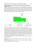
Fig. 2. Analogy of the geometry of a Phantom Omni device and an excavator manipulator
This chapter is organized as follows: Section 2 gives an overview of haptic feedback in mobile
hydraulic machines. In Section 3 an alternative operational concept for excavators is pro-
posed. Section 4 discusses the interconnection of the position controllers of the haptic device
and the hydraulic excavator leading to a control methodology for bilateral master-slave sys-
tems. Section 5 introduces the applied controller design method, namely internal model con-
trol (IMC), for integrating plants with input constraints. After describing the controller design
for the electric actuators of the haptic device and for the hydraulic actuators of the excava-
tor, experimental results are given in Section 6. Section 7 shows the results of initial usability
experiments with test drivers and Section 8 offers some conclusions.
2. Haptic Feedback in Mobile Hydraulic Machines
The automation level of available mobile machines is low, with the exception of some special
applications like forest machines or robotic cargo loading systems. Due to the increasing use
of automation technology, research and development activities focus on new human-machine
interfaces and operational concepts. They aim at improving efficiency, safety and comfort. A
prerequisite for innovative human-machine interfaces is the availability of electrohydraulics
and the corresponding controllers. Then, new functions like driver assistance and safety sys-
tems can be integrated in the controller software as well as alternative operating devices. In
the future, the level of automation in mobile machines will increase up to complete automa-
tion (Haas & Kim, 2002).
The integration of the sense of touch in the human-machine interface promises an easier, faster
and more intuitive operation than the typically encountered visual information. Haptic inter-
faces have advantages, compared to human-machine interfaces that do not integrate the sense
of touch, especially if the operator has to work delicately and accurately, or if various materials
– for example with different elasticity – are handled.
Haptically enhanced assistance systems can support the driver of a mobile machine in per-
forming his working task by providing tactile sensations via the operating device. Haptic
driver assistance systems for hydraulic excavators could for example
• warn the driver of damaging obstacles,
• feed back digging or gripping forces,
• imitate open-center hydraulic systems,
• enable the driver to sense the inertia of the machine’s manipulator,
• simplify leveling and slope cutting,
• limit the excavator’s workspace,
• guide the bucket on a specific trajectory, or
• assist the collaborative manipulation of a heavy building element by multiple operators.
A significant advantage of haptic systems compared to semi- or fully automated assistance
systems is, that the operator always has complete control over his machine. The driver is able
to manually overrule the assistance systems, assuming that the human operator is always
stronger than the actuators of the haptic device.
The application of haptic technologies in human-machine interfaces of mobile machines is
not prior art in series-production vehicles. It can be found in some scientific contributions
and sporadic industrial projects, only. One finds that either the machines are controlled with
conventional force-feedback joysticks (Cemenska et al., 1989; Parker et al., 1993; Yamada &
Muto, 2003; Augustine, 2005) or special haptic operating devices whose segments resemble
the manipulator geometry (Ostoja-Starzewski & Skibniewski, 1989; Yoshinada & Takeda, 1990;
Kraft, 1991; Kontz, 2007). The same principle is known from industrial robots and similar
manipulators. An overview of haptic interface technology for mobile machines, like hydraulic
excavators, can be found in Hayn & Schwarzmann (2008).
3. Development of an Intuitive Operational Concept for Hydraulic Excavators
Alternatives to conventional operational concepts are known but did not become widely ac-
cepted. The most important reasons are:
• Electrohydraulics was not available for series-production at reasonable prices,
• mechanical-hydraulic components are known for being robust and reliable, and
• the mobile machinery industry has a rather conservative attitude towards alternative
operational concepts.
In order to design an intuitive operational concept for the hydraulic manipulator of excava-
tors the coordinated control approach was developed further. It was assumed that operating
elements that resemble the manipulator geometry are intuitive and easy to use. These operat-
ing elements have the same degree of freedom, the same types of joints and the same moving
direction as the machine that has to be controlled. This property is called compatibility of the
moving directions (Sachs et al., 1994). This means in detail for the manipulator of an excava-
tor:
• The rotation of the cabin has to be controlled using a rotary operating element,
• the translation of the tool center point has to be controlled using an element which is
free-moving within a vertical plane, and
• tilting the bucket has to be controlled using a rotary element.
The realization of this idea was expected to result in an unambiguous, predictable, and con-
sistent, thus intuitive operational concept. When developing new operational concepts for
hydraulic excavators it is additionally important to consider the concept being ergonomic and
suitable for earthmoving machinery.
AHapticallyEnhancedOperationalConceptforaHydraulicExcavator 201
In this work, a SensAble Phantom Omni haptic device is used to generate the position refer-
ence signal for the tool center point (TCP) of the hydraulic manipulator of an 18 ton excavator.
The two arm segments of the operating device resemble the boom and stick of the excavator,
as shown in Fig. 2.
Fig. 2. Analogy of the geometry of a Phantom Omni device and an excavator manipulator
This chapter is organized as follows: Section 2 gives an overview of haptic feedback in mobile
hydraulic machines. In Section 3 an alternative operational concept for excavators is pro-
posed. Section 4 discusses the interconnection of the position controllers of the haptic device
and the hydraulic excavator leading to a control methodology for bilateral master-slave sys-
tems. Section 5 introduces the applied controller design method, namely internal model con-
trol (IMC), for integrating plants with input constraints. After describing the controller design
for the electric actuators of the haptic device and for the hydraulic actuators of the excava-
tor, experimental results are given in Section 6. Section 7 shows the results of initial usability
experiments with test drivers and Section 8 offers some conclusions.
2. Haptic Feedback in Mobile Hydraulic Machines
The automation level of available mobile machines is low, with the exception of some special
applications like forest machines or robotic cargo loading systems. Due to the increasing use
of automation technology, research and development activities focus on new human-machine
interfaces and operational concepts. They aim at improving efficiency, safety and comfort. A
prerequisite for innovative human-machine interfaces is the availability of electrohydraulics
and the corresponding controllers. Then, new functions like driver assistance and safety sys-
tems can be integrated in the controller software as well as alternative operating devices. In
the future, the level of automation in mobile machines will increase up to complete automa-
tion (Haas & Kim, 2002).
The integration of the sense of touch in the human-machine interface promises an easier, faster
and more intuitive operation than the typically encountered visual information. Haptic inter-
faces have advantages, compared to human-machine interfaces that do not integrate the sense
of touch, especially if the operator has to work delicately and accurately, or if various materials
– for example with different elasticity – are handled.
Haptically enhanced assistance systems can support the driver of a mobile machine in per-
forming his working task by providing tactile sensations via the operating device. Haptic
driver assistance systems for hydraulic excavators could for example
• warn the driver of damaging obstacles,
• feed back digging or gripping forces,
• imitate open-center hydraulic systems,
• enable the driver to sense the inertia of the machine’s manipulator,
• simplify leveling and slope cutting,
• limit the excavator’s workspace,
• guide the bucket on a specific trajectory, or
• assist the collaborative manipulation of a heavy building element by multiple operators.
A significant advantage of haptic systems compared to semi- or fully automated assistance
systems is, that the operator always has complete control over his machine. The driver is able
to manually overrule the assistance systems, assuming that the human operator is always
stronger than the actuators of the haptic device.
The application of haptic technologies in human-machine interfaces of mobile machines is
not prior art in series-production vehicles. It can be found in some scientific contributions
and sporadic industrial projects, only. One finds that either the machines are controlled with
conventional force-feedback joysticks (Cemenska et al., 1989; Parker et al., 1993; Yamada &
Muto, 2003; Augustine, 2005) or special haptic operating devices whose segments resemble
the manipulator geometry (Ostoja-Starzewski & Skibniewski, 1989; Yoshinada & Takeda, 1990;
Kraft, 1991; Kontz, 2007). The same principle is known from industrial robots and similar
manipulators. An overview of haptic interface technology for mobile machines, like hydraulic
excavators, can be found in Hayn & Schwarzmann (2008).
3. Development of an Intuitive Operational Concept for Hydraulic Excavators
Alternatives to conventional operational concepts are known but did not become widely ac-
cepted. The most important reasons are:
• Electrohydraulics was not available for series-production at reasonable prices,
• mechanical-hydraulic components are known for being robust and reliable, and
• the mobile machinery industry has a rather conservative attitude towards alternative
operational concepts.
In order to design an intuitive operational concept for the hydraulic manipulator of excava-
tors the coordinated control approach was developed further. It was assumed that operating
elements that resemble the manipulator geometry are intuitive and easy to use. These operat-
ing elements have the same degree of freedom, the same types of joints and the same moving
direction as the machine that has to be controlled. This property is called compatibility of the
moving directions (Sachs et al., 1994). This means in detail for the manipulator of an excava-
tor:
• The rotation of the cabin has to be controlled using a rotary operating element,
• the translation of the tool center point has to be controlled using an element which is
free-moving within a vertical plane, and
• tilting the bucket has to be controlled using a rotary element.
The realization of this idea was expected to result in an unambiguous, predictable, and con-
sistent, thus intuitive operational concept. When developing new operational concepts for
hydraulic excavators it is additionally important to consider the concept being ergonomic and
suitable for earthmoving machinery.
AdvancesinHaptics202
After evaluation of different configurations of operating elements on a virtual reality excava-
tor simulator, the concept, shown on Fig. 3(a) as a virtual model, is proposed.
To improve the ergonomics the operating elements are scaled down to allow the manipulation
via small motions of the right hand instead of the full arm. The operating elements are inte-
grated into the arm rest to support effortless working. The sizes of the elements were adapted
by polystyrene models. Unlike the original coordinated control concept here the operation of
the manipulator is shared between both hands. The driver’s left hand operates the rotation
of the cabin. The right hand operates the position of the TCP in the x-y-plane on Fig. 2 and
the bucket. It is possible to invert both elements to facilitate the use by left-handed persons.
Fig. 3(b) shows the operating elements from the driver’s point of view.
(a) Front view (b) Driver’s view
Fig. 3. Intuitive operational concept for hydraulic excavators
The element for the operation of the TCP und the bucket is shown in detail on Fig. 4(a). The
two main segments resemble the manipulator geometry. The bucket is controlled by swiveling
the light gray, spring centered element. The slew drive for the rotating platform with the cabin
is operated with the left hand using the turning knob shown in Fig. 4(b). The turning knob is
divided into an inner dark gray disc and an outer light gray wheel. The inner disc can be used
to set a desired swing angle. The outer wheel is used to control the yaw rate. The outer wheel
allows positioning the rotating platform slowly and sensitively.
The operating elements are intended to be actuated in order to integrate haptically enhanced
driver assistance systems according to Section 2.
The concept was tested on a virtual reality excavator simulator and on a real 18 ton wheel
excavator. The proposed operational concept, which exists only as a virtual model, was eval-
uated using commercially available devices, namely a SensAble Phantom Omni device and a
3Dconnexion SpaceBall 5000, that are similar to the operating elements proposed before. The
driver’s right hand operates the SensAble Phantom Omni device. Unneeded degrees of free-
dom of the device, like the rotating platform, were locked into position. Instead of the turning
knob the 3Dconnexion SpaceBall 5000 was used to set the reference yaw rate. Fig. 5 shows the
operating devices mounted in the cabin of the test excavator.
(a) Element to operate the manipulator (b) Turning knob to rotate the cabin
Fig. 4. Enlarged view of the operating elements
4. Haptically Enhanced Master-Slave Control Methodology
4.1 Position Control Concept for Haptic Device and Excavator
The proposed operational concept is a typical bilateral master-slave system. The TCP of the
hydraulic manipulator arm (slave) follows the reference signal of the operating element (mas-
ter) on the right-hand side. However, in the case with an excavator as the slave, two issues
appear: First, the human operator needs to sense how far the excavator lags behind the oper-
ating device. Without this information, it is difficult to accurately position the machine since
the excavator moves significantly slower than the operator can move the operating device.
Thus, without some sensory information, the operator cannot know how much lag to expect.
Second, and more importantly, if the human operator releases the operating device (in steady-
state), the excavator should not start to move. Otherwise, considering the case when the de-
vice is not actuated, the handle will fall if the user lets go and, consequently, the boom moves
rapidly downwards as it follows the operating device. This behavior has to be avoided at all
times. This leads to the assumption that the operating element necessarily has to be actuated.
This was important for the technical realization of the proposed operational concept:
• The actuators are used to position-control the operating device in order to permanently
synchronize its position with the position of the TCP of the excavator.
• The actuated device gives the possibility to feed back if the driver moves the operating
element faster than the excavator can follow. This improves the handling quality of the
machine.
• The actuators can be used to implement haptic driver assistance systems.
Fig. 6 shows the block diagram of a haptic human-machine interface for an electrohydraulic
excavator including the human operator. Obviously, algorithms for the two controllers Q
hd
and Q
ex
have to be designed. The two controlled plants Σ are the haptic device (index hd)
and the excavator (index ex). w denotes the reference variable, u the actuating variable and
y the control variable, that is the output signal of each system. The physical representation
(mechanical, electric, hydraulic) of each signal is given.
A control methodology for the proposed operational concept had to be found. Typical control
concepts for bilateral teleoperator systems are based on the two-port network theory (Han-
naford, 1989; Zhu & Salcudean, 1995; Salcudean et al., 1997; Tafazoli et al., 2002; Huang, 2004).
AHapticallyEnhancedOperationalConceptforaHydraulicExcavator 203
After evaluation of different configurations of operating elements on a virtual reality excava-
tor simulator, the concept, shown on Fig. 3(a) as a virtual model, is proposed.
To improve the ergonomics the operating elements are scaled down to allow the manipulation
via small motions of the right hand instead of the full arm. The operating elements are inte-
grated into the arm rest to support effortless working. The sizes of the elements were adapted
by polystyrene models. Unlike the original coordinated control concept here the operation of
the manipulator is shared between both hands. The driver’s left hand operates the rotation
of the cabin. The right hand operates the position of the TCP in the x-y-plane on Fig. 2 and
the bucket. It is possible to invert both elements to facilitate the use by left-handed persons.
Fig. 3(b) shows the operating elements from the driver’s point of view.
(a) Front view (b) Driver’s view
Fig. 3. Intuitive operational concept for hydraulic excavators
The element for the operation of the TCP und the bucket is shown in detail on Fig. 4(a). The
two main segments resemble the manipulator geometry. The bucket is controlled by swiveling
the light gray, spring centered element. The slew drive for the rotating platform with the cabin
is operated with the left hand using the turning knob shown in Fig. 4(b). The turning knob is
divided into an inner dark gray disc and an outer light gray wheel. The inner disc can be used
to set a desired swing angle. The outer wheel is used to control the yaw rate. The outer wheel
allows positioning the rotating platform slowly and sensitively.
The operating elements are intended to be actuated in order to integrate haptically enhanced
driver assistance systems according to Section 2.
The concept was tested on a virtual reality excavator simulator and on a real 18 ton wheel
excavator. The proposed operational concept, which exists only as a virtual model, was eval-
uated using commercially available devices, namely a SensAble Phantom Omni device and a
3Dconnexion SpaceBall 5000, that are similar to the operating elements proposed before. The
driver’s right hand operates the SensAble Phantom Omni device. Unneeded degrees of free-
dom of the device, like the rotating platform, were locked into position. Instead of the turning
knob the 3Dconnexion SpaceBall 5000 was used to set the reference yaw rate. Fig. 5 shows the
operating devices mounted in the cabin of the test excavator.
(a) Element to operate the manipulator (b) Turning knob to rotate the cabin
Fig. 4. Enlarged view of the operating elements
4. Haptically Enhanced Master-Slave Control Methodology
4.1 Position Control Concept for Haptic Device and Excavator
The proposed operational concept is a typical bilateral master-slave system. The TCP of the
hydraulic manipulator arm (slave) follows the reference signal of the operating element (mas-
ter) on the right-hand side. However, in the case with an excavator as the slave, two issues
appear: First, the human operator needs to sense how far the excavator lags behind the oper-
ating device. Without this information, it is difficult to accurately position the machine since
the excavator moves significantly slower than the operator can move the operating device.
Thus, without some sensory information, the operator cannot know how much lag to expect.
Second, and more importantly, if the human operator releases the operating device (in steady-
state), the excavator should not start to move. Otherwise, considering the case when the de-
vice is not actuated, the handle will fall if the user lets go and, consequently, the boom moves
rapidly downwards as it follows the operating device. This behavior has to be avoided at all
times. This leads to the assumption that the operating element necessarily has to be actuated.
This was important for the technical realization of the proposed operational concept:
• The actuators are used to position-control the operating device in order to permanently
synchronize its position with the position of the TCP of the excavator.
• The actuated device gives the possibility to feed back if the driver moves the operating
element faster than the excavator can follow. This improves the handling quality of the
machine.
• The actuators can be used to implement haptic driver assistance systems.
Fig. 6 shows the block diagram of a haptic human-machine interface for an electrohydraulic
excavator including the human operator. Obviously, algorithms for the two controllers Q
hd
and Q
ex
have to be designed. The two controlled plants Σ are the haptic device (index hd)
and the excavator (index ex). w denotes the reference variable, u the actuating variable and
y the control variable, that is the output signal of each system. The physical representation
(mechanical, electric, hydraulic) of each signal is given.
A control methodology for the proposed operational concept had to be found. Typical control
concepts for bilateral teleoperator systems are based on the two-port network theory (Han-
naford, 1989; Zhu & Salcudean, 1995; Salcudean et al., 1997; Tafazoli et al., 2002; Huang, 2004).
AdvancesinHaptics204
Fig. 5. Test excavator equipped with operating devices
This approach is not applicable to the presented problem because the operating device and the
test excavator were not equipped with force sensors. Furthermore, transparency of the bilat-
eral system was not required. Consequentially, an alternative control concept was adopted to
solve the above-mentioned problems. The proposed solution is that two position controlled
plants (excavator and haptic device) provide the reference position to each other, i.e., each
system mirrors the position of the other system. Therefore, the operating device has to be
actuated and position-controlled to mirror the current position of the excavator’s arm. With
this approach, if the user releases the handle in steady-state, it remains at its current position.
Additionally, the haptic device will try to counteract the operator if it is moved away from
its reference position. The operator can interpret the resulting force of the haptic device as an
indication of the lag between the excavator and the operating device due to the inertia of the
hydraulic manipulator.
The control methodology for the full master-slave system consisting of the haptic device and
the excavator is shown in Fig. 7. Each plant output y
hd
and y
ex
is the reference signal for the
other system, i.e., each system mirrors the actual position of the other system. This intercon-
nected control loop works because the bandwidths of both systems differ significantly. The
operator input w
op
is modeled as an input disturbance d
op
of the haptic device.
Position controllers for both systems – haptic device and excavator – are desired. Since the
design method internal model control was utilized, as described later in Section 5 and 6, each
controller Q consists of an internal model controller C and a prefilter F
pre
. K
hd
and K
ex
are
constant transformations
w
ex
= k
1
·y
hd
+ k
2
(1)
w
hd
=
1
k
1
·y
ex
−
k
2
k
1
, (2)
Fig. 6. Haptic human-machine interface of an excavator
Fig. 7. Master-slave control loop
that convert the dimensions of the workspaces of one device to the other’s. Internal stability
of the system can be shown examining the poles of the relevant transfer functions.
The reference position is given in cylindrical coordinates: w
hd,x
, w
hd,y
, w
ex,x
, w
ex,y
for the
position of the TCP in a vertical plane (driven by boom and stick) and ϕ
set
for the angle of the
rotating platform (slew drive). The rotating platforms of both systems are single-input, single-
output (SISO) plants. In order to control the position of the TCP, a reference signal generator
is used. The reference signal generator converts the desired position into reference variables
for the electric joint actuators ϕ
ref
and the hydraulic cylinders l
ref,z1
, l
ref,z3
using the inverse
kinematics. In spite of the inaccuracy due to the static computation of the reference variables
using the inverse kinematics, this approach provides the advantage that the joint actuators
and cylinders can be treated as SISO systems and shows satisfactory experimental results.
Plants with static nonlinearities CC
−1
, which are the hydraulic actuators including the valves,
were treated by approximating them as Hammerstein models. The complete excavator control
system is shown in Fig. 8.
4.2 Implementation of Haptically Enhanced Assistance Systems
The proposed control methodology implicates haptic feedback of the inertia of the hydraulic
manipulator. Additional driver assistance systems like limiting the excavator’s workspace
or guiding the bucket on a specific trajectory are desired. These assistance systems can
be implemented as virtual fixtures simulating stiff walls (Rosenberg, 1993; Burdea, 1996).
Fig. 9 shows virtual walls within the workspace of the SensAble Phantom Omni. The an-
AHapticallyEnhancedOperationalConceptforaHydraulicExcavator 205
Fig. 5. Test excavator equipped with operating devices
This approach is not applicable to the presented problem because the operating device and the
test excavator were not equipped with force sensors. Furthermore, transparency of the bilat-
eral system was not required. Consequentially, an alternative control concept was adopted to
solve the above-mentioned problems. The proposed solution is that two position controlled
plants (excavator and haptic device) provide the reference position to each other, i.e., each
system mirrors the position of the other system. Therefore, the operating device has to be
actuated and position-controlled to mirror the current position of the excavator’s arm. With
this approach, if the user releases the handle in steady-state, it remains at its current position.
Additionally, the haptic device will try to counteract the operator if it is moved away from
its reference position. The operator can interpret the resulting force of the haptic device as an
indication of the lag between the excavator and the operating device due to the inertia of the
hydraulic manipulator.
The control methodology for the full master-slave system consisting of the haptic device and
the excavator is shown in Fig. 7. Each plant output y
hd
and y
ex
is the reference signal for the
other system, i.e., each system mirrors the actual position of the other system. This intercon-
nected control loop works because the bandwidths of both systems differ significantly. The
operator input w
op
is modeled as an input disturbance d
op
of the haptic device.
Position controllers for both systems – haptic device and excavator – are desired. Since the
design method internal model control was utilized, as described later in Section 5 and 6, each
controller Q consists of an internal model controller C and a prefilter F
pre
. K
hd
and K
ex
are
constant transformations
w
ex
= k
1
·y
hd
+ k
2
(1)
w
hd
=
1
k
1
·y
ex
−
k
2
k
1
, (2)
Fig. 6. Haptic human-machine interface of an excavator
Fig. 7. Master-slave control loop
that convert the dimensions of the workspaces of one device to the other’s. Internal stability
of the system can be shown examining the poles of the relevant transfer functions.
The reference position is given in cylindrical coordinates: w
hd,x
, w
hd,y
, w
ex,x
, w
ex,y
for the
position of the TCP in a vertical plane (driven by boom and stick) and ϕ
set
for the angle of the
rotating platform (slew drive). The rotating platforms of both systems are single-input, single-
output (SISO) plants. In order to control the position of the TCP, a reference signal generator
is used. The reference signal generator converts the desired position into reference variables
for the electric joint actuators ϕ
ref
and the hydraulic cylinders l
ref,z1
, l
ref,z3
using the inverse
kinematics. In spite of the inaccuracy due to the static computation of the reference variables
using the inverse kinematics, this approach provides the advantage that the joint actuators
and cylinders can be treated as SISO systems and shows satisfactory experimental results.
Plants with static nonlinearities CC
−1
, which are the hydraulic actuators including the valves,
were treated by approximating them as Hammerstein models. The complete excavator control
system is shown in Fig. 8.
4.2 Implementation of Haptically Enhanced Assistance Systems
The proposed control methodology implicates haptic feedback of the inertia of the hydraulic
manipulator. Additional driver assistance systems like limiting the excavator’s workspace
or guiding the bucket on a specific trajectory are desired. These assistance systems can
be implemented as virtual fixtures simulating stiff walls (Rosenberg, 1993; Burdea, 1996).
Fig. 9 shows virtual walls within the workspace of the SensAble Phantom Omni. The an-
AdvancesinHaptics206
Fig. 8. Control loop implemented on the test excavator using a SISO architecture
gular wall in Fig. 9(a) supports the operator in slope cutting, the vertical wall haptically limits
the workspace to protect the cabin of the excavator. Fig. 9(b) shows two walls building a slide
rail that give the operator the feeling to be guided on a defined trajectory.
Usually, virtual walls are simulated as spring or spring-damper systems and implemented by
adding a virtual force f
virtual
via the controller of the haptic device. In this case, the actuators
auf the haptic device are position- not force-controlled. Thus exerting such an external force
onto the haptic device will interfere with the position controller which will lead to undesired
results as the controller will try to counteract this seemingly undesired disturbance. In order
to circumvent this problem, the method to constrain the actuating variable, introduced in
Section 5.4, was applied to modulate the input constraints u
hd,min
and u
hd,max
dynamically
to achieve a spring-like behavior. As a result, the position controller is made aware of the
desired interference and will exert it on the haptic device itself. In a sense, the dynamic input
constraints are used to tell the position controller how to incorporate the desired behavior into
the running position control loop. The algorithm to calculate the constraints works as follows:
1. Computation of the spring force f
virtual
which depends on the distance d between the
TCP and the virtual wall:
f
virtual
=
f
virtual,x
f
virtual,y
= k
wall
n = k
wall
d
x
d
y
. (3)
n is a normal vector with the length d.
0.1 0.12 0.14 0.16 0.18 0.2 0.22 0.24 0.26
−0.08
−0.06
−0.04
−0.02
0
0.02
0.04
0.06
0.08
x [m]
y [m]
(a) Slope assistance and workspace limitation
0.1 0.12 0.14 0.16 0.18 0.2 0.22 0.24 0.26
−0.08
−0.06
−0.04
−0.02
0
0.02
0.04
0.06
0.08
x [m]
y [m]
(b) Trajectory guidance
Fig. 9. Virtual walls within the workspace of the haptic device
2. If the TCP penetrates the virtual wall (d
≤ 0) two moments M
virtual
for both segments
of the operating element are calculated:
M
virtual,1
= u
hd,feedback,1
=
k
wall
l
1
·
d
x
sin ϕ
2
−d
y
sin ϕ
2
sin ϕ
1
sin ϕ
2
+ cos ϕ
1
cos ϕ
2
(4)
M
virtual,2
= u
hd,feedback,2
=
k
wall
l
2
·
−
d
x
cos ϕ
1
−d
y
sin ϕ
1
sin ϕ
1
sin ϕ
2
+ cos ϕ
1
cos ϕ
2
. (5)
These moments generate the desired force at the TCP. The equation results from the
kinematics of the haptic device. l and ϕ denote the lengths and angles as shown in
Fig. 10. These calculated moments and the actuating variable u
hd
of the electric actu-
ators of the device are proportional (M
virtual
∼ u
hd
). Hence the actuating variable to
generate the desired force f
virtual
via these moments is called u
hd,feedback
.
3. The constraints u
hd,min
and u
hd,max
of the actuating variables of both segments are
u
hd,min
= u
hd,limit,min
+ u
hd,gravity
+ u
hd,feedback
, (6)
u
hd,max
= u
hd,limit,max
+ u
hd,gravity
+ u
hd,feedback
. (7)
u
hd,limit
is the physical input constraint of each plant according to Section 5.4. u
hd,gravity
is a constant that compensates the influence of gravity on the haptic device even if the
control deviation is null. The constraints u
hd,min
and u
hd,max
are applied according to
Equations (30) and (31).
The adopted constraints force the haptic device to behave like a stiff spring if the TCP is
within the predefined fixtures. After adjusting k
wall
in experiments this approach showed
good results. The simulated stiff wall can be sensed easily.
AHapticallyEnhancedOperationalConceptforaHydraulicExcavator 207
Fig. 8. Control loop implemented on the test excavator using a SISO architecture
gular wall in Fig. 9(a) supports the operator in slope cutting, the vertical wall haptically limits
the workspace to protect the cabin of the excavator. Fig. 9(b) shows two walls building a slide
rail that give the operator the feeling to be guided on a defined trajectory.
Usually, virtual walls are simulated as spring or spring-damper systems and implemented by
adding a virtual force f
virtual
via the controller of the haptic device. In this case, the actuators
auf the haptic device are position- not force-controlled. Thus exerting such an external force
onto the haptic device will interfere with the position controller which will lead to undesired
results as the controller will try to counteract this seemingly undesired disturbance. In order
to circumvent this problem, the method to constrain the actuating variable, introduced in
Section 5.4, was applied to modulate the input constraints u
hd,min
and u
hd,max
dynamically
to achieve a spring-like behavior. As a result, the position controller is made aware of the
desired interference and will exert it on the haptic device itself. In a sense, the dynamic input
constraints are used to tell the position controller how to incorporate the desired behavior into
the running position control loop. The algorithm to calculate the constraints works as follows:
1. Computation of the spring force f
virtual
which depends on the distance d between the
TCP and the virtual wall:
f
virtual
=
f
virtual,x
f
virtual,y
= k
wall
n = k
wall
d
x
d
y
. (3)
n is a normal vector with the length d.
0.1 0.12 0.14 0.16 0.18 0.2 0.22 0.24 0.26
−0.08
−0.06
−0.04
−0.02
0
0.02
0.04
0.06
0.08
x [m]
y [m]
(a) Slope assistance and workspace limitation
0.1 0.12 0.14 0.16 0.18 0.2 0.22 0.24 0.26
−0.08
−0.06
−0.04
−0.02
0
0.02
0.04
0.06
0.08
x [m]
y [m]
(b) Trajectory guidance
Fig. 9. Virtual walls within the workspace of the haptic device
2. If the TCP penetrates the virtual wall (d
≤ 0) two moments M
virtual
for both segments
of the operating element are calculated:
M
virtual,1
= u
hd,feedback,1
=
k
wall
l
1
·
d
x
sin ϕ
2
−d
y
sin ϕ
2
sin ϕ
1
sin ϕ
2
+ cos ϕ
1
cos ϕ
2
(4)
M
virtual,2
= u
hd,feedback,2
=
k
wall
l
2
·
−
d
x
cos ϕ
1
−d
y
sin ϕ
1
sin ϕ
1
sin ϕ
2
+ cos ϕ
1
cos ϕ
2
. (5)
These moments generate the desired force at the TCP. The equation results from the
kinematics of the haptic device. l and ϕ denote the lengths and angles as shown in
Fig. 10. These calculated moments and the actuating variable u
hd
of the electric actu-
ators of the device are proportional (M
virtual
∼ u
hd
). Hence the actuating variable to
generate the desired force f
virtual
via these moments is called u
hd,feedback
.
3. The constraints u
hd,min
and u
hd,max
of the actuating variables of both segments are
u
hd,min
= u
hd,limit,min
+ u
hd,gravity
+ u
hd,feedback
, (6)
u
hd,max
= u
hd,limit,max
+ u
hd,gravity
+ u
hd,feedback
. (7)
u
hd,limit
is the physical input constraint of each plant according to Section 5.4. u
hd,gravity
is a constant that compensates the influence of gravity on the haptic device even if the
control deviation is null. The constraints u
hd,min
and u
hd,max
are applied according to
Equations (30) and (31).
The adopted constraints force the haptic device to behave like a stiff spring if the TCP is
within the predefined fixtures. After adjusting k
wall
in experiments this approach showed
good results. The simulated stiff wall can be sensed easily.
AdvancesinHaptics208
Fig. 10. Kinematics of a SensAble Phantom Omni
5. Internal Model Control of Linear SISO Systems
The proposed control methodology in Fig. 8 demands several controllers, one for each plant
in both systems. Since both types of plants (electric joint actuators of the SensAble Phantom
Omni device as well as the hydraulic cylinders and the slew drive of the excavator) show an
integrating behavior, the same control method, namely internal model control for integrating
linear SISO systems, is chosen for all plants. A review of the design is given in the following,
starting with non-integrating plants, i.e., plants Σ having i poles p
i
with Re{p
i
} < 0 for all i.
5.1 IMC for Non-Integrating Stable Systems
The main idea of IMC is to include a model
˜
Σ of the plant Σ into the controller K, as shown in
Fig. 11. If
˜
Σ models the plant Σ exactly and in the absence of disturbances (d
= 0), the feedback
signal equals zero (y
(t) −
˜
y
(t) = 0), and the IMC controller Q is a feed-forward controller.
Fig. 11. IMC structure
The IMC controller Q is a series connection of a filter F and the inverse model
˜
Σ
−1
:
Q
= F
˜
Σ
−1
. (8)
For non-integrating plants, in Frank (1974) and Morari & Zafiriou (1989), the following struc-
ture for the filter F is proposed:
F
(s) =
1
(
1
λ
s + 1)
r
with λ > 0 , (9)
where λ is a design parameter and r is the relative degree of
˜
Σ.
The IMC structure can always be converted into the standard control loop shown in
Fig. 12 (Schwarzmann, 2007):
C =
1
1
− F
Q
=
F
1
− F
˜
Σ
−1
= F
tot
˜
Σ
−1
. (10)
Fig. 12. IMC structure implemented in a standard control loop
The separation of the controller C into a filter F
tot
and the inverse of a model
˜
Σ
−1
is required
for the proposed limitation of the controller output u in Section 5.4.
5.2 IMC for Integrating Systems
The previously proposed filter F in Equation (9) and the resulting filter F
tot
are not sufficient
for integrating systems because step input disturbances d lead to a steady-state offset (Morari
& Zafiriou, 1989). The filter F
tot
has to have at least the same relative degree as
˜
Σ and i + 1 pure
integrators (i.e. poles at zero) in order to design a proper controller C, where i is the number of
pure integrators of the plant model
˜
Σ. According to the design procedure presented in Morari
& Zafiriou (1989), a system of linear equations has to be solved to determine the filter F for this
type of plants. To avoid this difficulty, a modified design rule for F is introduced to design an
internal model controller for integrating linear minimum phase systems in a standard control
loop. This modified design rule leads to the same result as the proposed solution by Morari &
Zafiriou (1989) but in a single step as opposed to solving a system of equations.
To generate the desired filter F
tot
from the positive feedback loop of F (cf. Equation (10)), F is
chosen in such a manner that terms δ
i
s
i
up to the i-th order of the denominator polynomial of
F are canceled by subtracting the numerator. The corresponding filter F is
F
(s) =
γ
i
λ
i
s
i
+
γ
i−1
λ
i−1
s
i−1
+ . +
γ
2
λ
2
s
2
+
γ
1
λ
s + 1
γ
r+i
λ
r+i
s
r+i
+ . +
γ
i
λ
i
s
i
+ . +
γ
1
λ
s + 1
=
δ
i
s
i
+ δ
i−1
s
i−1
+ . + δ
2
s
2
+ δ
1
s + 1
(
1
λ
s + 1)
r+i
(11)
with δ
n
=
γ
n
λ
n
, 0 ≤ n ≤ i .
The numerator of F consists of all terms up to the i-th order of the polynomial of the extended
denominator of F (
(
1
λ
s + 1)
r+i
), which are the last i + 1 summands of the denominator. λ is a
design parameter, r is the relative degree of
˜
Σ, γ and δ are constant coefficients. F
tot
is then
AHapticallyEnhancedOperationalConceptforaHydraulicExcavator 209
Fig. 10. Kinematics of a SensAble Phantom Omni
5. Internal Model Control of Linear SISO Systems
The proposed control methodology in Fig. 8 demands several controllers, one for each plant
in both systems. Since both types of plants (electric joint actuators of the SensAble Phantom
Omni device as well as the hydraulic cylinders and the slew drive of the excavator) show an
integrating behavior, the same control method, namely internal model control for integrating
linear SISO systems, is chosen for all plants. A review of the design is given in the following,
starting with non-integrating plants, i.e., plants Σ having i poles p
i
with Re{p
i
} < 0 for all i.
5.1 IMC for Non-Integrating Stable Systems
The main idea of IMC is to include a model
˜
Σ of the plant Σ into the controller K, as shown in
Fig. 11. If
˜
Σ models the plant Σ exactly and in the absence of disturbances (d
= 0), the feedback
signal equals zero (y
(t) −
˜
y
(t) = 0), and the IMC controller Q is a feed-forward controller.
Fig. 11. IMC structure
The IMC controller Q is a series connection of a filter F and the inverse model
˜
Σ
−1
:
Q
= F
˜
Σ
−1
. (8)
For non-integrating plants, in Frank (1974) and Morari & Zafiriou (1989), the following struc-
ture for the filter F is proposed:
F
(s) =
1
(
1
λ
s + 1)
r
with λ > 0 , (9)
where λ is a design parameter and r is the relative degree of
˜
Σ.
The IMC structure can always be converted into the standard control loop shown in
Fig. 12 (Schwarzmann, 2007):
C =
1
1 − F
Q
=
F
1 − F
˜
Σ
−1
= F
tot
˜
Σ
−1
. (10)
Fig. 12. IMC structure implemented in a standard control loop
The separation of the controller C into a filter F
tot
and the inverse of a model
˜
Σ
−1
is required
for the proposed limitation of the controller output u in Section 5.4.
5.2 IMC for Integrating Systems
The previously proposed filter F in Equation (9) and the resulting filter F
tot
are not sufficient
for integrating systems because step input disturbances d lead to a steady-state offset (Morari
& Zafiriou, 1989). The filter F
tot
has to have at least the same relative degree as
˜
Σ and i + 1 pure
integrators (i.e. poles at zero) in order to design a proper controller C, where i is the number of
pure integrators of the plant model
˜
Σ. According to the design procedure presented in Morari
& Zafiriou (1989), a system of linear equations has to be solved to determine the filter F for this
type of plants. To avoid this difficulty, a modified design rule for F is introduced to design an
internal model controller for integrating linear minimum phase systems in a standard control
loop. This modified design rule leads to the same result as the proposed solution by Morari &
Zafiriou (1989) but in a single step as opposed to solving a system of equations.
To generate the desired filter F
tot
from the positive feedback loop of F (cf. Equation (10)), F is
chosen in such a manner that terms δ
i
s
i
up to the i-th order of the denominator polynomial of
F are canceled by subtracting the numerator. The corresponding filter F is
F
(s) =
γ
i
λ
i
s
i
+
γ
i−1
λ
i−1
s
i−1
+ . +
γ
2
λ
2
s
2
+
γ
1
λ
s + 1
γ
r+i
λ
r+i
s
r+i
+ . +
γ
i
λ
i
s
i
+ . +
γ
1
λ
s + 1
=
δ
i
s
i
+ δ
i−1
s
i−1
+ . + δ
2
s
2
+ δ
1
s + 1
(
1
λ
s + 1)
r+i
(11)
with δ
n
=
γ
n
λ
n
, 0 ≤ n ≤ i .
The numerator of F consists of all terms up to the i-th order of the polynomial of the extended
denominator of F (
(
1
λ
s + 1)
r+i
), which are the last i + 1 summands of the denominator. λ is a
design parameter, r is the relative degree of
˜
Σ, γ and δ are constant coefficients. F
tot
is then
AdvancesinHaptics210
F
tot
(s) =
F
1 − F
=
numerator(F)
denominator(F) −numerator(F)
=
δ
i
s
i
+ δ
i−1
s
i−1
+ . + δ
2
s
2
+ δ
1
s + 1
(
1
λ
s + 1)
r+i
−δ
i
s
i
− . −δ
2
s
2
−δ
1
s −1
=
γ
i
λ
i
s
i
+
γ
i−1
λ
i−1
s
i−1
+ . +
γ
2
λ
2
s
2
+
γ
1
λ
s + 1
γ
r+i
λ
r+i
s
r+i
+ . +
γ
i+1
λ
i+1
s
i+1
(12)
=
γ
i
λ
i
s
i
+
γ
i−1
λ
i−1
s
i−1
+ . +
γ
2
λ
2
s
2
+
γ
1
λ
s + 1
s
i+1
(
γ
r+i
λ
r+i
s
r
+
γ
r+i−1
λ
r+i−1
s
r−1
+ . +
γ
i+1
λ
i+1
)
.
This results in the desired number of integrators in F
tot
. The tuning parameter λ determines
the resulting bandwidth of the closed loop. The specified design rule for F
tot
allows to follow
ramp reference signals and removes the steady-state offset in the case of step input distur-
bances.
5.3 Prefilter Design
A prefilter F
pre
is introduced to reduce overshoot. This leads to a second degree of freedom to
parameterize the behavior of the closed loop.
If
˜
Σ is an ideal model of the plant Σ, the transfer behavior of the closed loop system is equal
to the filter F (see Fig. 11). Hence the desired behavior F
d
of the system can be forced by the
prefilter
F
pre
= F
d
F
-1
. (13)
The desired behavior F
d
is usually a low-pass filter
F
d
=
1
(
1
λ
d
s + 1)
r
d
(14)
with the design parameter λ
d
. This holds if r
d
is greater than or equal to the relative degree
of F.
5.4 Input Constraints
In technical systems, the actuating variable u is limited: u ∈ [u
min
,u
max
]. When neglected,
this input constraint of the plant can lead to undesirable windup effects. Especially the haptic
device shows these effects because of the persistent integration of the position error variable
due to the operator holding the handle of the device. If not treated by the control algorithm,
the result is a strong integral windup effect if the user releases the handle of the haptic device.
Due to the design specifications overshoot is not desired. Therefore, a windup compensation
according to Schwarzmann (2007) was designed as follows:
If the IMC controller Q is implemented as a series connection of F and the inverse of the plant
model
˜
Σ
−1
(cf. Fig. 12), a constraint of the highest derivative
˜
y
(r)
d
of the filter output limits the
output u of the controller. Using this structure, the filter F forces a desired behavior
˜
y
d
of the
plant that does not violate the input constraints u
min
and u
max
of the plant Σ.
According to Graichen & Zeitz (2006) the inverse of a model
˜
Σ can be determined as follows:
A controllable model
˜
Σ
˜
Σ :
˙
x
= f
f
f (x
x
x,u), x
x
x(0) = x
x
x
0
,
˜
y = h(x
x
x) (15)
with a relative degree r, defined as
r
= argmin
k
{
∂
∂u
L
k
f
h(x
x
x,u) = 0} , (16)
where L
f
h means the Lie-derivative of h with respect to f , can be transformed to the nonlinear
normal form
˜
y
(r)
= α(
˜
y,
˙
˜
y,.
˜
y
(r−1)
,η
η
η,u) (17a)
˙
η
= β
β
β(η
η
η,
˜
y,
˙
˜
y,.
˜
y
(r−1)
,u) (17b)
with α
(·) = L
r
f
h ◦φ
φ
φ
−1
and β(·) = L
f
φ
n,i
◦φ
φ
φ
−1
using the state transformation
[
˜
y,
˙
˜
y,.
˜
y
(r−1)
,η
η
η]
T
= φ
φ
φ(x
x
x) with (18a)
˜
y
(i)
= L
i
f
h(x
x
x) = φ
i+1
, i = 0, ,r −1 (18b)
η
η
η
= φ
φ
φ
η
(x
x
x) ∈ R
n−r
. (18c)
The inverse of the model
˜
Σ is then
˜
Σ
-1
: u = α
−1
(
˜
y
d
,
˙
˜
y
d
,
˜
y
(r)
d
,η
η
η) (19a)
˙
η
= β
β
β(η
η
η,
˜
y
d
,
˙
˜
y
d
,
˜
y
(r−1)
d
,u) , (19b)
where the function α
−1
is the solution of Equation (17a) for u.
For linear systems
˜
y
=
˜
Σu without zeros, the controller output u
=
˜
Σ
-1
˜
y can be described as
u
= u(
˜
y
d
,
˙
˜
y
d
, ,
˜
y
(r−1)
d
,
˜
y
(r)
d
) = a
0
˜
y
d
+ a
1
˙
˜
y
d
+ . + a
(r−1)
˜
y
(r−1)
d
+ a
r
˜
y
(r)
d
. (20)
For the above-named systems with i integrators at the plant output, the controller output u is
not a function of the desired behavior
˜
y
d
and its first i −1 derivatives
u
= u(
˜
y
(i)
d
,
˜
y
(i+1)
d
, ,
˜
y
(r−1)
d
,
˜
y
(r)
d
) = a
i
˜
y
(i)
d
+ a
i+1
˜
y
(i+1)
d
+ . + a
(r−1)
˜
y
(r−1)
d
+ a
r
˜
y
(r)
d
. (21)
Note that this is an algebraic equation. To obtain the necessary derivatives
˜
y
(r)
d
for the inverse
of the model, the filter F was implemented as a state-variable filter (SVF) as shown in Fig. 14.
This structure allows to limit the highest derivative
˜
y
(r)
d
in order to constrain the actuating
variable u.
The limits
˜
y
(r)
d,min
and
˜
y
(r)
d,max
can be calculated by solving Equation (19a) for
˜
y
(r)
and using
Equation (21):
˜
y
(r)
d,min
= min
u∈[u
min
,u
max
]
(
¯
α
(
˜
y
d
,
˙
˜
y
d
, ,
˜
y
(r−1)
d
,u)) (22a)
˜
y
(r)
d,max
= max
u∈[u
min
,u
max
]
(
¯
α
(
˜
y
d
d,
˙
˜
y
d
, ,
˜
y
(r−1)
d
,u)) . (22b)
AHapticallyEnhancedOperationalConceptforaHydraulicExcavator 211
F
tot
(s) =
F
1
− F
=
numerator(F)
denominator(F) −numerator(F)
=
δ
i
s
i
+ δ
i−1
s
i−1
+ . + δ
2
s
2
+ δ
1
s + 1
(
1
λ
s + 1)
r+i
−δ
i
s
i
− . −δ
2
s
2
−δ
1
s −1
=
γ
i
λ
i
s
i
+
γ
i−1
λ
i−1
s
i−1
+ . +
γ
2
λ
2
s
2
+
γ
1
λ
s + 1
γ
r+i
λ
r+i
s
r+i
+ . +
γ
i+1
λ
i+1
s
i+1
(12)
=
γ
i
λ
i
s
i
+
γ
i−1
λ
i−1
s
i−1
+ . +
γ
2
λ
2
s
2
+
γ
1
λ
s + 1
s
i+1
(
γ
r+i
λ
r+i
s
r
+
γ
r+i−1
λ
r+i−1
s
r−1
+ . +
γ
i+1
λ
i+1
)
.
This results in the desired number of integrators in F
tot
. The tuning parameter λ determines
the resulting bandwidth of the closed loop. The specified design rule for F
tot
allows to follow
ramp reference signals and removes the steady-state offset in the case of step input distur-
bances.
5.3 Prefilter Design
A prefilter F
pre
is introduced to reduce overshoot. This leads to a second degree of freedom to
parameterize the behavior of the closed loop.
If
˜
Σ is an ideal model of the plant Σ, the transfer behavior of the closed loop system is equal
to the filter F (see Fig. 11). Hence the desired behavior F
d
of the system can be forced by the
prefilter
F
pre
= F
d
F
-1
. (13)
The desired behavior F
d
is usually a low-pass filter
F
d
=
1
(
1
λ
d
s + 1)
r
d
(14)
with the design parameter λ
d
. This holds if r
d
is greater than or equal to the relative degree
of F.
5.4 Input Constraints
In technical systems, the actuating variable u is limited: u ∈ [u
min
,u
max
]. When neglected,
this input constraint of the plant can lead to undesirable windup effects. Especially the haptic
device shows these effects because of the persistent integration of the position error variable
due to the operator holding the handle of the device. If not treated by the control algorithm,
the result is a strong integral windup effect if the user releases the handle of the haptic device.
Due to the design specifications overshoot is not desired. Therefore, a windup compensation
according to Schwarzmann (2007) was designed as follows:
If the IMC controller Q is implemented as a series connection of F and the inverse of the plant
model
˜
Σ
−1
(cf. Fig. 12), a constraint of the highest derivative
˜
y
(r)
d
of the filter output limits the
output u of the controller. Using this structure, the filter F forces a desired behavior
˜
y
d
of the
plant that does not violate the input constraints u
min
and u
max
of the plant Σ.
According to Graichen & Zeitz (2006) the inverse of a model
˜
Σ can be determined as follows:
A controllable model
˜
Σ
˜
Σ :
˙
x
= f
f
f (x
x
x,u), x
x
x(0) = x
x
x
0
,
˜
y = h(x
x
x) (15)
with a relative degree r, defined as
r
= argmin
k
{
∂
∂u
L
k
f
h(x
x
x,u) = 0} , (16)
where L
f
h means the Lie-derivative of h with respect to f , can be transformed to the nonlinear
normal form
˜
y
(r)
= α(
˜
y,
˙
˜
y,.
˜
y
(r−1)
,η
η
η,u) (17a)
˙
η
= β
β
β(η
η
η,
˜
y,
˙
˜
y,.
˜
y
(r−1)
,u) (17b)
with α
(·) = L
r
f
h ◦φ
φ
φ
−1
and β(·) = L
f
φ
n,i
◦φ
φ
φ
−1
using the state transformation
[
˜
y,
˙
˜
y,.
˜
y
(r−1)
,η
η
η]
T
= φ
φ
φ(x
x
x) with (18a)
˜
y
(i)
= L
i
f
h(x
x
x) = φ
i+1
, i = 0, ,r −1 (18b)
η
η
η
= φ
φ
φ
η
(x
x
x) ∈ R
n−r
. (18c)
The inverse of the model
˜
Σ is then
˜
Σ
-1
: u = α
−1
(
˜
y
d
,
˙
˜
y
d
,
˜
y
(r)
d
,η
η
η) (19a)
˙
η
= β
β
β(η
η
η,
˜
y
d
,
˙
˜
y
d
,
˜
y
(r−1)
d
,u) , (19b)
where the function α
−1
is the solution of Equation (17a) for u.
For linear systems
˜
y
=
˜
Σu without zeros, the controller output u
=
˜
Σ
-1
˜
y can be described as
u
= u(
˜
y
d
,
˙
˜
y
d
, ,
˜
y
(r−1)
d
,
˜
y
(r)
d
) = a
0
˜
y
d
+ a
1
˙
˜
y
d
+ . + a
(r−1)
˜
y
(r−1)
d
+ a
r
˜
y
(r)
d
. (20)
For the above-named systems with i integrators at the plant output, the controller output u is
not a function of the desired behavior
˜
y
d
and its first i −1 derivatives
u
= u(
˜
y
(i)
d
,
˜
y
(i+1)
d
, ,
˜
y
(r−1)
d
,
˜
y
(r)
d
) = a
i
˜
y
(i)
d
+ a
i+1
˜
y
(i+1)
d
+ . + a
(r−1)
˜
y
(r−1)
d
+ a
r
˜
y
(r)
d
. (21)
Note that this is an algebraic equation. To obtain the necessary derivatives
˜
y
(r)
d
for the inverse
of the model, the filter F was implemented as a state-variable filter (SVF) as shown in Fig. 14.
This structure allows to limit the highest derivative
˜
y
(r)
d
in order to constrain the actuating
variable u.
The limits
˜
y
(r)
d,min
and
˜
y
(r)
d,max
can be calculated by solving Equation (19a) for
˜
y
(r)
and using
Equation (21):
˜
y
(r)
d,min
= min
u∈[u
min
,u
max
]
(
¯
α
(
˜
y
d
,
˙
˜
y
d
, ,
˜
y
(r−1)
d
,u)) (22a)
˜
y
(r)
d,max
= max
u∈[u
min
,u
max
]
(
¯
α
(
˜
y
d
d,
˙
˜
y
d
, ,
˜
y
(r−1)
d
,u)) . (22b)
AdvancesinHaptics212
This means that the actuating variable u is constrained exactly to [u
min
,u
max
] if the highest
derivative
˜
y
(r)
d
is restricted to these limits.
6. Controller Design for the Operating Device and for the Excavator
6.1 Design Procedure
The controllers in Fig. 8 were designed utilizing the IMC method. The following procedure
was used to design the IMC controllers for the haptic device (electric motors) and the excava-
tor (electrohydraulic valves to control the boom, stick, and bucket cylinders):
1. Take measurements of the static and dynamic behavior of the plant Σ (gain and step
response)
2. Parameter identification of the parametric model in Equation (23) for each actuator
3. IMC controller design using the parameterized models
4. Design of a prefilter to minimize overshoot
This approach allows a straightforward controller development. The prefilters in Fig. 8 are
needed since a large peak overshoot is not acceptable due to safety reasons: The excavator
boom is not allowed to exceed its reference position because it could damage objects close
to the bucket. The additional prefilter converts the structure to a two-degrees-of-freedom
controller.
To this end, the plant models were chosen as an integrator and a first-order filter:
˜
Σ
=
k
s(Ts + 1)
, (23)
where parameter k is the gain and T is the time constant of the low-pass filter. The model
parameters were determined by measurements. The controllers C and prefilters F
pre
were
designed according to Section 5.
6.2 Controller Design for the Haptic Device
The actuating variables for the SensAble Phantom Omni haptic device are the motor currents
of each joint. The output variables are the joint angles. Fig. 13 shows the step response of
the first segment and the actuating variable u
hd,1
. The actuating variable does not return to
zero as the effect of gravity requires the electric motors of the haptic device to be actuated
permanently to hold their positions.
As mentioned before, the controller of the haptic device requires an anti-windup strategy
according to Section 5.4. As a consequence, F
tot
was implemented as the state-variable filter
shown in Fig. 14. The used filter F
tot
F
tot
=
δ
1
s + 1
δ
3
s
3
+ δ
2
s
2
(24)
leads to the differential equation
y
(3)
d
+
δ
2
δ
3
y
(2)
d
=
δ
1
δ
3
u
(1)
+
1
δ
3
u . (25)
The system can also be described in controllable standard form (Lunze, 2006) as
0 0.5 1 1.5 2 2.5
0
0.2
0.4
0.6
0.8
1
Time (s)
w, u, y
ϕ
ref,
1
u
hd,
1
ϕ
act,
1
Fig. 13. Step response of the first segment of the haptic device
˙
x
x
x
tr
=
0 1 0
0 0
δ
3
−δ
1
δ
2
δ
2
3
0 0 −
δ
2
δ
3
x
x
x
tr
+
0
δ
1
δ
3
1
u (26)
˜
y
d
=
1 0 0
x
x
x
tr
(27)
by using the transformation x
x
x
tr
= T
T
T
R
x
x
x with
T
T
T
R
=
1
δ
3
δ
1
δ
3
0
0
1
δ
3
δ
1
δ
3
0 0 1
. (28)
The transformed system can be implemented as the block diagram shown in Fig. 14. Note the
integrator chain at the output of F
tot
.
The algebraic model of each actuated segment j of the operating element is
k
j
·
¨
y
hd,j
+
˙
y
hd,j
= T
j
·u
hd,j
. (29)
Utilizing the algebraic model Σ
hd
allows to compute the constraints for the highest derivative
¨
y
hd
according to Section 5.4:
¨
y
hd,min
=
1
k
j
(−
˙
y
hd
+ T
1,j
·u
hd,min
) , (30)
¨
y
hd,max
=
1
k
j
(−
˙
y
hd
+ T
1,j
·u
hd,max
) . (31)
AHapticallyEnhancedOperationalConceptforaHydraulicExcavator 213
This means that the actuating variable u is constrained exactly to [u
min
,u
max
] if the highest
derivative
˜
y
(r)
d
is restricted to these limits.
6. Controller Design for the Operating Device and for the Excavator
6.1 Design Procedure
The controllers in Fig. 8 were designed utilizing the IMC method. The following procedure
was used to design the IMC controllers for the haptic device (electric motors) and the excava-
tor (electrohydraulic valves to control the boom, stick, and bucket cylinders):
1. Take measurements of the static and dynamic behavior of the plant Σ (gain and step
response)
2. Parameter identification of the parametric model in Equation (23) for each actuator
3. IMC controller design using the parameterized models
4. Design of a prefilter to minimize overshoot
This approach allows a straightforward controller development. The prefilters in Fig. 8 are
needed since a large peak overshoot is not acceptable due to safety reasons: The excavator
boom is not allowed to exceed its reference position because it could damage objects close
to the bucket. The additional prefilter converts the structure to a two-degrees-of-freedom
controller.
To this end, the plant models were chosen as an integrator and a first-order filter:
˜
Σ
=
k
s
(Ts + 1 )
, (23)
where parameter k is the gain and T is the time constant of the low-pass filter. The model
parameters were determined by measurements. The controllers C and prefilters F
pre
were
designed according to Section 5.
6.2 Controller Design for the Haptic Device
The actuating variables for the SensAble Phantom Omni haptic device are the motor currents
of each joint. The output variables are the joint angles. Fig. 13 shows the step response of
the first segment and the actuating variable u
hd,1
. The actuating variable does not return to
zero as the effect of gravity requires the electric motors of the haptic device to be actuated
permanently to hold their positions.
As mentioned before, the controller of the haptic device requires an anti-windup strategy
according to Section 5.4. As a consequence, F
tot
was implemented as the state-variable filter
shown in Fig. 14. The used filter F
tot
F
tot
=
δ
1
s + 1
δ
3
s
3
+ δ
2
s
2
(24)
leads to the differential equation
y
(3)
d
+
δ
2
δ
3
y
(2)
d
=
δ
1
δ
3
u
(1)
+
1
δ
3
u . (25)
The system can also be described in controllable standard form (Lunze, 2006) as
0 0.5 1 1.5 2 2.5
0
0.2
0.4
0.6
0.8
1
Time (s)
w, u, y
ϕ
ref,
1
u
hd,
1
ϕ
act,
1
Fig. 13. Step response of the first segment of the haptic device
˙
x
x
x
tr
=
0 1 0
0 0
δ
3
−δ
1
δ
2
δ
2
3
0 0 −
δ
2
δ
3
x
x
x
tr
+
0
δ
1
δ
3
1
u (26)
˜
y
d
=
1 0 0
x
x
x
tr
(27)
by using the transformation x
x
x
tr
= T
T
T
R
x
x
x with
T
T
T
R
=
1
δ
3
δ
1
δ
3
0
0
1
δ
3
δ
1
δ
3
0 0 1
. (28)
The transformed system can be implemented as the block diagram shown in Fig. 14. Note the
integrator chain at the output of F
tot
.
The algebraic model of each actuated segment j of the operating element is
k
j
·
¨
y
hd,j
+
˙
y
hd,j
= T
j
·u
hd,j
. (29)
Utilizing the algebraic model Σ
hd
allows to compute the constraints for the highest derivative
¨
y
hd
according to Section 5.4:
¨
y
hd,min
=
1
k
j
(−
˙
y
hd
+ T
1,j
·u
hd,min
) , (30)
¨
y
hd,max
=
1
k
j
(−
˙
y
hd
+ T
1,j
·u
hd,max
) . (31)
AdvancesinHaptics214
Fig. 14. State-variable filter for the haptic device controller including input constraints
6.3 Controller Design for the Hydraulic Boom
The actuating variables for the hydraulic cylinders of the excavator are the flow rates of the
hydraulic oil that the valves distribute to each cylinder or to the slew drive. The output vari-
ables are the cylinder positions or the angle of the rotating platform, respectively. Fig. 15
shows the step response of the boom cylinder and the actuating variable u
ex,z1
.
0 1 2 3 4 5 6 7 8 9 10
0
0.2
0.4
0.6
0.8
1
Time (s)
w, u, y
l
ref,z1
u
ex,z1
l
act,z1
Fig. 15. Step response of the excavator’s boom cylinder
Model errors result in an acceptable overshoot. The oscillations of the machine on its tyres can
be seen in the measurements.
6.4 Experimental Results
The master-slave control approach introduced in Section 4 shows satisfying results in experi-
ments on the test excavator. The controller for the SensAble Phantom Omni device was run-
ning under MATLAB/Simulink. The boom controller was implemented on dSPACE proto-
typing hardware. Position sensors for the hydraulic cylinders and an angular rate sensor for
the rotating platform were utilized to measure the actual position of the machine.
The step response of the x-y-controlled hydraulic arm in the horizontal direction x is shown
on Fig. 16 (a). The position error in the vertical direction y is less than
± 0.05 m (cf. Fig. 16 (b)).
0 1 2 3 4 5 6 7 8 9 10
0
0.2
0.4
0.6
0.8
1
Time (s)
w(m), u, y(m)
(a)
w
ex,x
u
ex,z1
u
ex,z3
y
ex,x
0 1 2 3 4 5 6 7 8 9 10
−0.04
−0.02
0
0.02
0.04
Time (s)
y(m)
(b)
y
ex,y
Fig. 16. Step response of the hydraulic arm
The behavior of the interconnected master-slave system is shown on Fig. 17. The position
signals w
ex,x
and w
ex,y
of the haptic device are low-pass filtered. This was necessary to achieve
a smooth reference signal for the excavator. The operator used the haptic device to prescribe
the curve in Fig. 18.
7. Evaluation of the Haptically Enhanced Operational Concept
Goal of the proposed operational concept is to improve the handling quality and to simplify
the operation — especially for untrained drivers. This target was evaluated by usability ex-
periments with test operators. The configuration using a SensAble Phantom Omni and a
3Dconnexion SpaceBall 5000, as shown in Fig. 5, was used to proof this concept. Twelve male
test operators without any relevant experience with hydraulic excavators performed a pre-
defined working task. They were filmed to analyze the working cycle times and operating
errors. Finally the test persons were surveyed using a questionnaire.
AHapticallyEnhancedOperationalConceptforaHydraulicExcavator 215
Fig. 14. State-variable filter for the haptic device controller including input constraints
6.3 Controller Design for the Hydraulic Boom
The actuating variables for the hydraulic cylinders of the excavator are the flow rates of the
hydraulic oil that the valves distribute to each cylinder or to the slew drive. The output vari-
ables are the cylinder positions or the angle of the rotating platform, respectively. Fig. 15
shows the step response of the boom cylinder and the actuating variable u
ex,z1
.
0 1 2 3 4 5 6 7 8 9 10
0
0.2
0.4
0.6
0.8
1
Time (s)
w, u, y
l
ref,z1
u
ex,z1
l
act,z1
Fig. 15. Step response of the excavator’s boom cylinder
Model errors result in an acceptable overshoot. The oscillations of the machine on its tyres can
be seen in the measurements.
6.4 Experimental Results
The master-slave control approach introduced in Section 4 shows satisfying results in experi-
ments on the test excavator. The controller for the SensAble Phantom Omni device was run-
ning under MATLAB/Simulink. The boom controller was implemented on dSPACE proto-
typing hardware. Position sensors for the hydraulic cylinders and an angular rate sensor for
the rotating platform were utilized to measure the actual position of the machine.
The step response of the x-y-controlled hydraulic arm in the horizontal direction x is shown
on Fig. 16 (a). The position error in the vertical direction y is less than
± 0.05 m (cf. Fig. 16 (b)).
0 1 2 3 4 5 6 7 8 9 10
0
0.2
0.4
0.6
0.8
1
Time (s)
w(m), u, y(m)
(a)
w
ex,x
u
ex,z1
u
ex,z3
y
ex,x
0 1 2 3 4 5 6 7 8 9 10
−0.04
−0.02
0
0.02
0.04
Time (s)
y(m)
(b)
y
ex,y
Fig. 16. Step response of the hydraulic arm
The behavior of the interconnected master-slave system is shown on Fig. 17. The position
signals w
ex,x
and w
ex,y
of the haptic device are low-pass filtered. This was necessary to achieve
a smooth reference signal for the excavator. The operator used the haptic device to prescribe
the curve in Fig. 18.
7. Evaluation of the Haptically Enhanced Operational Concept
Goal of the proposed operational concept is to improve the handling quality and to simplify
the operation — especially for untrained drivers. This target was evaluated by usability ex-
periments with test operators. The configuration using a SensAble Phantom Omni and a
3Dconnexion SpaceBall 5000, as shown in Fig. 5, was used to proof this concept. Twelve male
test operators without any relevant experience with hydraulic excavators performed a pre-
defined working task. They were filmed to analyze the working cycle times and operating
errors. Finally the test persons were surveyed using a questionnaire.